5-1/4"
Winchester Disk Drive Controller
Service Manual
June, 1987
PAGE STATUS
EFFFX!TIVE DATE
Page status iii/iv June, 1987
Table of Contents v through viii June, 1987
Preface lX June, 1987
Section 1 x through 1-8 June, 1987
Section 2 2-1 through 2-8 June, 1987
Section 3 3-1 through 3-28 June, 1987
Section 4 4-1 through 4-4 June, 1987
Section 5 5-1 through 5-2 June, 1987
Appendix A A-1 through A-38 June, 1987
Appendix B B-1 through B-48 June, 1987
SEX!l'1<E 1
1.1 1.2 1.2.1 1.2.2 1.3 1.4 1.5 1.6
2.1 2.2 2.2.1 2.2.2 2.3 2.3.1 2.3.2
3.1 3.1.1 3.1.2 3.2 3.2.1 3.2.2 3.2.3 3.2.4 3.2.5 3.2.6 3.2.6.1 3.2.6.2 3.2.6.3 3.2.7 3.2.8 3.2.9 3.2.10 3.2.10.1 3.2.10.2 3.2.10.3 3.2.10.4 3.2.11 3.2.11.1 3.2.11.2 3.2.11.3
TABLE OF <DlrENl'S
Page
General • • • • • • • • • • • • • • • • • • • • • • • • • • • • • • • • • •••••••••••••••• 1-1 PCBA l)escription... •••••• 1-1 Single-Bc>ard WIX:! •••••••••••••••••••••••••••••••••••• 1-1
'lWo-Bc>ard WIX:! ••••••••••••••••••••••••••••••••••••• •• 1-4
Adapter Section Features ... 1-4 Controller Section Features •••••••••••••••• ~ •••••••••••• 1-5
~ifications ••••••••••••••••••••••••••••••••••• " ••••••• 1-6
Related Publications •••••••••••••••••••••••••••••••••••• 1-6
General ••••••••••••••••••••••••••••••••••••••••••••••••• 2-1 Single Bc>ard WDC •••••••••••••••••••••••••••••••••••••••• 2-1 Unpacking/Packing Instructions •••••••.• " •••••••••••••• 2-1 Installation Requirements ••••••••••••••••••••••••••• 2-1 'lWo-Bc>a.rd WDC ••••••••••••••••••••••••••••••••••••••••••• 2-4
Unpacking/Packing Instructions •••••••••••••••••••••• 2-4 Installation Requirements ••••••••••••• ~ ••••••••••••• 2-4
General ... 3-1 Adaptor Section Functions ••••••••••••••••••••••••••• 3-1 Controller Section Functions •••••••••••••••••••••••• 3-3 System I/O Interface •••••••••••••••••••••••••••••••••••• 3-3 WDC I/O Addresses ••••••••••••••••••••••••••••••••••• 3-3 WDC Transaction ••••••••••••••••••••••••••••••••••••• 3-5 Completion Status Byte •••••••••••••••••••••••••••••• 3-7 Error Sensing ••••••••••••••••••••••••••••••••••••••• 3-7 Sense Byte Structure •••••••••••••••••••••••••••••••• 3-7 Error Codes ••••••••••••••••••••••••••••••••••••••••• 3-8 Class 00 Error Codes •••••••••••••••••••••••••••• 3-8 Class 01 Error Codes •••••••••••••••••••••••••••• 3-8 Class 02 Error Codes •••••••••••••••••••••••••••• 3-8 Power UP/Reset •••••••••••••••••••••••••••••••••••••• 3-9 Power Down/Power Fail Detect •••••••••••••••••••••••• 3-10 Disk Drive Formatting ••••••••••••••••••••••••••••••• 3-10 BOSS IX System to WDC Sequencing •••••••••••••••••••• 3-10 output Buffer Empty status •••••••••••••••••••••• 3-10 Direct Fetching of Data ••••••••••••••••••••••••• 3-11 Unpacking Data Registers •••••••••••••••••••••••• 3-11 Generating Internal Bus Requests •••••••••••••••• 3-11 WDC to BOSS IX System Sequencing •••••••••••••••••••• 3-11 Input Buffer Empty status ••••••••••••••••••••••• 3-12 Operation Complete status •••••• -••••••••••••••••• 3-12 Direct Loading of Data •••••••••••••••••••••••••• 3-12
3.2.11.4 3.2.12 3.2.12.1 3.2.12.2 3.3
3.3.1 3.3.1.1 3.3.1.2 3.3.1.3 3.3.1.4 3.3.1.5 3.3.1.6 3.3.1.7 3.3.1.8 3.3.1.9 3.3.1.10 3.3.1.11 3.3.1.12 3.3.1.13 3.3.1.14 3.3.1.15 3.3.1.16 3.3.2 3.3.2.1 3.3.2.2 3.3.2.3 3.3.2.4 3.3.2.5 3.3.2.6 3.3.2.7 3.3.2.8
SEX!tlOO 4
4.1 4.2 4.2.1 4.2.2 4.2.2.1 4.2.2.2 4.2.3 4.2.3.1 4.2.3.2
SFX;TlCE 5
APPJH)IX A APPEHlIX B
ltJ158A
· TABLE OF cnn'EN.l'S (cont' d)
Page
FONC1'I<EAL DES:RIP.l'ICE (coot' d)
Generating Internal Bus Requests •••••••••••••••• 3-12 Diagnostic Features ••••••••••••••••••••••••••••••••• 3-13 Register and Buffer Tests ••••••••••••••••••••••• 3-13 r:MA and Interrupt Logic Tests •••••• · ••••••••••••• 3-13 Detailed Description of Conmand Description Block (COB). 3-14 Class 00 Command Descriptions ••••••••••••••••••••••• 3-14 Class 00 Corcma.nd Code Stmmary ••••••••••••••••••• 3-15 Test Unit Ready (Op Code OOh) ••••••••••••••••••• 3-15 Rezero Unit (Op Code 01h) ••••••••••••••••••••••• 3-15 Request Sense (Op Code 03h) ••••••••••••••••••••• 3-16 Format Unit (Op Code 04h) ••••••••••••••••••••••• 3-16 Read (Op Code 08h) •••••••••••••••••••••••••••••• 3-17 Write (Op Code OAb) ••••••••••••••••••••••••••••• 3-17 Seek (Op Code OBh,) •••••••••••••••••••••••••••••• 3-18 Translate (Op Code OFh) •••••••••••••••••• ' ••••••• 3-18 Write Data Buffer (Op Code 13h) ••••••••••••••••• 3-19 Read Buffer RAM (Op Code 14h) ••••••••••••••••••• 3-19 Mode Select (Op Code 15h) ••••••••••••••••••••••• 3-19 Mode Sense (Op Code lAb) •••••••••••••••••••••••• 3-21 start/stop (Op Code IBh) ••••••••••••••••••••••• ~3-22
Receive Diagnostic Result (Op Code lCh) ••••••••• 3-22 Send Diagnostic (Op Code 1Dh) ••••••••••••••••••• 3-23 Class 01 Commands ••••••••••••••••••••••••••••••••••• 3-24 COB Class 01 Command Code Summary ••••••••••••••• 3-24 CBD Class 01 Command Block Format ••••••••••••••• 3-25 Read Capacity (Op Code 25h) ••••••••••••••••••••• 3-25 Read (Op Code 28h) •••••••••••••••••••••••••••••• 3-25 Write (Op Code 2A) •••••••••••••••••••••••••••••• 3-26 Write and Verify (Op Code 2Eh) •••••••••••••••••• 3-26 Verify (Op Code 2Fh) •••••••••••••••••••••••••••• 3~26 Search Data Equal (Op Code 31h) ••••••••••••••••• 3-26
Preventive r1a.intenance •••••••••••••••••••••••••••••••••• 4-1 Corrective l13.intenance... • •• '. • • •••••••• 4-1 Power-Up Initialization and Self-Test ••••••••••••••• 4-1 System Diagnostics •••••••••••••••••••••••••••••••••• 4-2 Register and Buffer Tests ••••••••••••••••••••••• 4-2 DMA and Interrupt Logic Tests ••••••••••••••••••• 4-2
WOC Adjus~nts ••••••••••••••••••••••••••••••••••••• 4-3
Test Equipment Required ••••••••••••••••••••••••• 4-3 Data Separator Adjus~nt ••••••••••••••••••••••• 4-3 REMOv.AL ••••• ~ ••••••••••••••••••••••••••••••• 5-1 SINGLE-BOARD MOe ~ AIDS ••••••••••••••••••••••• A-l
~BOARD
woe
AIDS ••••••••••• ~ •••••••••••••• B-lFigure 1-1 1-2 2-1 2-2 3-1 A-1 A-2 A-3 A-4 A-5 A-6 A-7 A-8 A-9 A-10 B-1 B-2 B-3 B-4 B-5 B-6 B-7 B-8 B-9 B-10 B-11 B-12
LIST OF ILLUSTRATIOOS
Page 5-1/4 Inch Winchester Disk Drive Controller ••••••••••••• x
woe PCBA Location of Major Components ••••••••••••••••••• 1-3
Single-Board cable, Jumper and SWitch Connections ••••••• 2-3 Two-Board cable, Jumper and SWitch Connections •••••••••• 2-6
woe
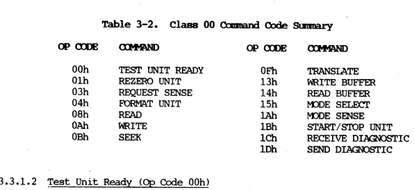
Functional Block Diagram •••••••••••••••••••••••••••• 3-2 BOSS IX System WRITE T~ng Diagram ••••••••••••••••••••• A-2 BOSS IX System READ T~ng Diagram •••••••••••••••••••••• A-3 BOSS IX System to woe Progranmed I/O PAL state Diagram •• A-4woe to BOSS IX Progranmed (M2\ PAL state Diagram ••••••••• A-5 DMA WRITE Operation T~ng Diagram •••••••••••••••••••••• A-7
woe to BOSS IX System Progranmed I/O PAL State Diagram •• A-8
woe to BOSS IX System Progranmed DMA PAL State Diagram •• A-9 Interrupt PAL State Diagram and Signal Listing •••••••••• A-12 Part No. 903496-001, Parts" Location Diagram ••••••••••••• A-18 Part No. 903496-001, Schematic Diagram (12 Sheets) •••••• A-25 BOSS IX System to
woe
Progranmed I/O PAL T~ng Diagram.B-2 BOSS IX System towoe
Progranmed I/O PAL State Diagram •• B-3 BOSS IX System towoe
Progranmed DMA PAL T~ng Diagram.B~4woe
to BOSS IX System Progranmed (M2\ PAL State Diagram •• B-5woe to BOSS IX System Progranmed I/O PAL T~ng Diagram.B-7
woe to BOSS IX System Progranmed I/O PAL State Diagram •• B-8
woe to BOSS IX System Prografimed DMA PAL Timing Diagram. B-9
woe to BOSS IX System Progranmed DMA PAL State Diagram •• B-10 Part No. 903439-001, Parts Location Diagram ••••••••••••• B-14 Part No. 903439-001, Logic Diagram •••••••••••••••••••••• B-17 Part No. 907649-001, Parts Location Diagram ••••••••••••• B-30 Part No. 907649-001, Logic Diagram •••••••••••••••••••••• B-33
Table
1-1 1-2 3-1 3-2 3-3 3-4 A-1 A-2 A-3 A-4 A-5 A-6 A-7 A-8 A-9 A-10 B-1 B-2 B-3 B-4 B-5 B-6
M8158A
Page
5-1/4" Winchester Disk Drives Su)::p)rted by the WOC •••••• 1-2 Winchester Disk Drive Specifications •••••••••••••••••••• 1-6 Class 00 Command Block Format ••••••••••••••••••••••••••• 3-13 Class 00 Command Code Summary ••••••••••••••••••••••••••• 3-14 COB Class 01 Command Code Summary ••••••••••••••••••••••• 3-23 Class 01 Command Block Format ••••••••••••••••••••••••••• 3-24 BOSS IX System to
woe
PAL Signal Listing •••••••••••••••• A-6 BOSS IX System towoe
PAL State Diagram ... A-10 Address PAL and Arbitration PAL Signal Listing •••••••••• A-11 Microprocessor Memory and IIO Addressing Map •••••••••••• A-13 BOSS IX System IIO Bus (EBUS) Interface Signal[)escriptions •••••••••••••••••••••••••••••••••••••••• A-14 SCSI Interface Signal Descriptions •••••••••• · •••••••••••• A-15 Drive Interface Signal Descriptions ••••••••••••••••••••• A-16 List of WOC Mnemonics ••••••••••••••••••••••••••••••••••• A-17 Part No. 903496-001, List of Parts (3 Sheets) ••••••••••• A-19 . Part No. 903496-002, List of Parts (3 Sheets) ••••••••••• A-22 BOSS IX System to
woe
PAL Signal Listing •••••••••••••••• B-6 BOSS IX System IIO Bus (EBUS) Interface SignalDescriptions •••••••••••••••••••••••••••••••••••••••• B-11 SCSI Interface Signal Descriptions •••••••••••••••••••••• B-12 List of WOC Mnemonics ••••••••••••••••••••••••••••••••••• B-13 Part No. 903439-001, List of Parts •••••••••••••••••••••• B-15 Part No. 907649-001, List of Parts •••••••••••••••••••••• B-31
This manual provides service information for the Winchester Controller for the 5-1/4 Inch Disk Drives. This information is presented as an aid for field service personnel, and supports the installation, operation, and maintenance of the Controller.
The major topics covered in this manual are: Section 1
Section 2 Section 3 Section 4 Section 5 Appendix A Appendix B
Introduction Installation
Functional Description Maintenance
Removal/Replacement
Single-Board
woe
Maintenance Aids Two-Boardwoe
Maintenance AidsThis equ:ipnent generates, uses, ard can radiate radio f~
energy and i f not installed ard used in acco:rdalx!e with the
in-structions manual, llBy canse interference to radio cammri.cations.
It has been tested and found to CCIlply with the limits for a Class
A O"A.pIting device pn-suant to
suqart
J of Part 15 of FCC Rules,which are designed to provide reasonable protection against. such
interf~ when operated in a ca:rauercial enviromelt. Operation
of this eqnipnent in a residential area is likely to cause
inter-f~ in which case the user at his own expense will be required
to take whatever measures that llBy be
requ:ii-ed
to correct thein-terference.
The use of shielded 1/0 cables is required when connecting unit to
any ard all optional
periPleral
or host devices. Failure to do somay violate FCC rules.
!
UI,
~
f
...~
•
~
...
~
g
~
~
~
~
[
~
21
6A~n
- 1 n £0»00;0:0DtPIl
H "
5A~ul
4A~ lJ"ll~"""~
fll!illmoIml
7C~I
GC~
[II
38~~=~O"':
0
;o~!l~28
R 2 6 C D L I R221
4 C{A21~ ~O~fjl~!! +~
~ oQQ~i
~
00
60
{f~o.'40
{
®e~~~~~rf7M~U'-CI\
....
R27 5
4
E'R2 C31
();l;f~ ~
WOO
~S
00
-< " 001
4E (JI -~
DDPIII N _ 6F g
"~13E ~f~yl;iC
2+
~
I
Q)~
5F { I E71
Em
.
~O--...
1 3F~
I
ollc...l6 H
~
D-tU
5H~
1 :;: 2 Fm
r
1 Ft
__ 31 C32- 4H
{N
1
3H { [ QL
gl
5J~OI
C23 - 2Hf" I
...
-'H·--<O
_ 6K )X
42
- 4J
{II
3J = 0.. 1136
)J
1
5K1m
C24~
I -
1 Jin
.6
00M
I
6L~I
C3J 4 K
101
3K~
O!!J
f.l~nn~1
7M~~o
t'
5L{QI
4L~ur
3L .. IK{g. · ·
1~11~l'1
_"
I
Cll C26{I'L
{O
.... 1 n.
)~ll
0+" 5Md-
41.1~OI
3MEi
-!39
C441
~"
35 C27~
a
1 U{O
_
-'J
r
7P{~
5PJ~I
4Nml
3N CI6~l.1
qp
1
TPI)0_1
4P Cj0
8ci~[
1 N {()'-IIJJ!::
7Rri
l b 1 - l " )1
3 p n " n(,a
Oi.m~
21
5R~..
<..JI
1 P{Ii
_~
7T{to
1 4 R~
1 3 R In~
N-fUc..
_~
n )LIR {U_ 1
7U1
{~
5 U~~
1
4 T{I
3 T{~I
1 T {g
g
I
3U{QI
IUm
to 0
TP8CJl~ AP2
a
a
1.1 GEMm\L
The Winchester Disk Drive Controller (WOC), Figure 1-1, provides the means by which an BOSS IX system corrmunicates with one or two 5-1/4" Winchester disk drives. The controller is comprised of two functionally independent sections, an Adapter section and a Controller section. The adapter section provides an interface between the host's I/O bus and the SCSI (Small Computer System
Interface) bus in the
woe.
In the current version of the
woe,
Part No. 903496, the Adapter section and the Controller section are physically combined on a single PCBA (printed cir-cuit board assembly). In the older version of thewoe,
Part No. 903439, the SCSI Bus Adapter, Part No. 907649, is m:>unted "piggy-back" sty Ie on top of the controller portion. Either configuration allows the.woe
to support one or two Winchester disk'drives with disk capacities ranging from 10 to 190 megabytes. Table 1-1 lists the 5-1/4" Winchester (fixed) disk drives that are sUH?Orted by thewoe.
1.2 PCBA DES:!RIPl'IOO
1.2.1 Single-Board NJC
J
The single-board
woe
consists of a PCBA which is designed for I/O stack m:>unt-ing in the system housm:>unt-ing. All components are m:>unted on one side of thehoard and soldered except for the macroprocessor and sequencer, all PAL
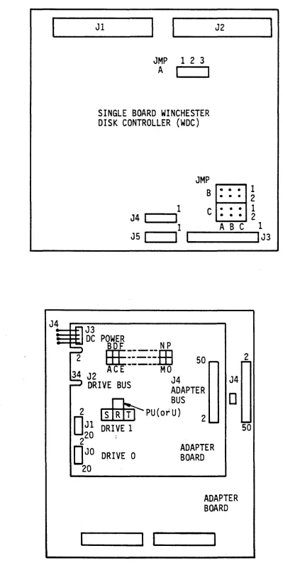
(program array logic) chips, PROYI and static RAM chips, encoder/decoder chips and buffer controller chips. These ICs are socketed for ready exchange or re-placement. In addition to the electronic and electrical components, the PCBA also contains three jumper blocks, a (green) LED indicator and five electrical connectors, whose locations are shown in Figure 1-2.
The single board
woe
1S not supported in the MAl 3000 system.~
~
Table 1-1 •. 5-1/4" Wi.nchester Disk Drives ~rts by the ~
Vendor UnfODD. Fonoat. NlBber Nlmi:Jer Bytes Seetonl tb1iler Average Used
fblel' MM Caple. C'.aplc. of of per per of Access On
NtDber ID ftIJyte ftIJyte Tracks Reads Sector Track Cylinders Time System
1085 85 85.32 71.3 8192 8 512 17 1024 28 MSEC 2000
3000
1105 90 105.1 87.89 10098 11 512 17 918 27 MSEC 2000
3000
1140 123 143.4 126.9 13770 15 1024 9 918 27 MSEC 1~00
1140 120 143.5 119.85 13770 15 512 17 918 27 MSEC 1500
2000 3000
2190 190 191.24 159.81 18360 15 512 17 1224 30 MSEC 3000
1304 43 51.9 43.35 4980 6 512 17 830 30 MSEC 1600
2000
...
I 1304 86 103.8 86.69 9960 12 512 17 830 30 MSEC (1) 1600N (2) 2000
1324 43/60 64 43.35 6144 6 512 17 1024 28 MSEC (3) 2000
1325 65/75 85.3 71.3 8192 8 512 17 1024 28 MSEC 2000
201 10 13.33 10.49 1280 2 256 32 640 90 MSEC S10
202 20 26.66 20.97 2560 8 256 32 320 90 MSEC S10
202 20 26.66 22.28 2560 8 512 17 320 90 MSEC 1600
2000
202 44 53.32 44.56 5120 16 512 17 320 90 MSEC (4) 1600
203E 30 40 33.42 3840 6 512 17 640 55 MSEC 2000
203E 30 40 31'.46 3840 6 512 .17 640 55 MSEC 1500
204E 40 53.33 44.56 5120 8 512 17 640 55 MSEC 2000
ST225 20 25.62 20.15 2460 4 512 17 615 65 MSEC 1500
ST4026 20 25.62 20.15 2460 4 512 17 615 40 MSEC 1500
wrES: (1) DUAL 43'S (2) DUAL 43'S
Jl
JMP 1 2 3 A
I
I
SINGLE BOARD WINCHESTER DISK CONTROLLER (WDC)
JMP
B
1 C
J4
I
I
1
J5
I
I
I
J4==iJ-F'l J3
:::: :fl DC POWER
BDF N P
J2
• • •
• • •
• • • • • •
ABC
2
HE::=--':.m
50 - ~34 AC E --- MO
J2 J4 J4
DRIVE BUS ADAPTER
~ BUS
0
1 2
1
2
0
2 Jl DRIVE 1[ll[ill
~ PU (or U) 2 ....So
220 JD
JO DRIVE 0 ADAPTER BOARD 20ADAPTER BOARD
11...-_ _
... 1 1'--_ _
... 1
I
1
IJ3
Figure 1-2. NlC PCm\ lDcation of Major catpments
[image:13.818.185.585.86.899.2]1.2.2 rno-Board NlC
The two-board WOC consists of a PCBA containing the.Controller section of the
WDC which is Irounted, piggy':'back sty Ie, onto the
PCBA
containing the Adaptersection. The WDC., consisting of both boards, is roounted on the I/O stack in the system housing. All cooplnents of the boards are Irounted on one side of the board· and soldered except for the microprocessor and sequencer PAL
(program array logic) chips, PRCM and static RAM chips, and selected
encoder / decoder chips. These ICs are socketed for ready exchange or
replace-ment. In addition to the electronic and electrical cOOIX>nents, the Adapter
also contains an 8-p::>sition DIP switch, a (green) LED indicator, and three electrical connectors. DC p::.>wer is applied to the Adaptec Controller through a four-pin cable assembly which is hard-wired to the Adapter board. The
Adapter board is similarly
equiFPErl
except that no DC J:X>Wer connection 1.Sre-quired. See Figure 1-2.
1.3 AD.Z\PTF.R SEX!1"IOO FFATORES
The Adapter section oper~tes as a Type 1 bus master and will DMA 16 bits at a
time; that is only on I:M2\. word boundaries. Overall operations perforined by
the Adapter section include:
o Progranmable vectored interrupt to the host when a disk conmand or disk
seek is completed (single-board woe only). The interrupt is hard-wired
as a level 2 interrupt (7 is highest). Interrupts can be enabled or disabled by host corrrnand.
~
o DMA and interrupt arbitration with up to 15 other controllers for
con-trol of the
ross
IX system I/O bus when requesting a r:MA transfer orduring an interrupt acknowledge cycle.
o Provisions for allowing one or two WDCs (single-board WDC only) to
oper-ate independently on an ross IX system I/O bus, using jumper blocks on
the PCBA.
o Bi -directional datal driver registers or transceivers which combine two
8-bit data latches for input and two 8-bit data latches for output to form two 16-bit registers.
o Address registers and drivers consisting of six 4-bit register/counter/
driver devices capable of addressing the
ross
IX system main mem:>ry asfollows:
32 megabytes on the single-board WDC
2 megabytes on the two-board woe
o Control logic which provides the appropriate interface between the
ross IX system I/O bus and the controller's SCSI bus. The logic starts
IJv1A or Interrupt cycles when necessary and handles packing and unpacking of the data transferred between the 16-bit I/O bus and the internal 8-bit bus.
The Controller section consists of a daisy-chained control bus and a radial data bus.
The control bus handles all the control functions of the disk drive/controller
.
interface, primarily in the form of ~5-volt DC control signals. The radial data bus handles read and write MFM data in the form of differential signals. Write prec~nsation can be set for either Drive 0 or Drive 1 by means ofj~rs on the PCBA. (In a two-board controller , write precQJl1?ensation is NOT
individually selectable for each drive.) Also, precompensation may be set to be always on, always off, or enabled at and beyond the reduced write current cy linder, using the jumpers.
OVerall operations performed by the Controller section include:
o Support for standard SCSI conmands, including a high speed data search conmand.
o A dual-ported 1k-byte data buffer for rapid data transfers with no sec-tor interleaving required.
o Transparent (to the host) disk defect handling. No spare tracks are re-quired, ~l iroinating long seeks to alternate tracks.
o Programmable logical addressing to access variable length (256, 512 'or 1024 byte) blocks.
o Self configuring on power. up, including: reading and storing drive
parameter data on Track 0; and copying and saving the largest block ad-dress and defect counts.
o Multiple block data transfers and inplied Seek, by imbedding logical block addresses within the basic Read and Write requests.
o Host-programmable disk parameters such as number of cylinders, heads and sectors. Sector interleaving and sector size, as well as ·step type and rate, are also programmable by the host.
o (On the single-board WOC) Interrupt-driven overlapped Seek operations, which allows one drive to be available for use while the other is
seek-ing. The Seek Complete interrupt can be enabled and disabled by host conmand.
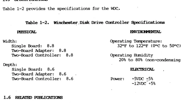
1.5 SP~FICATIOOS
Table 1-2 provides the specifications for the WDC .•
Table 1-2. ~_Disk: Drive Controller Specifications
PHYSICAL
width:
Single Board:
B.B
Two-Board Adapter:
B • B
Two-Board Controller:B.B
Depth:Single Board:
B.6
Two-Board Adapter: B • 6
Two-Board Controller:
B.6
1.6 RElATED POBLICATIOOS
Operating Temperature:
32°F to 122°F (O°C to 500C) Operating Humadity
20% to BO% (non-condensing)
Power: +5VDC +5%
-12VDC +5%
The following servicing documentation may be used in conjunction with this publication for the 5-1/4" Winchester Disk Controller:
o MB079, MAI 2000 System Service Manual
o MBOB3, 5-1/4" Fixed Media Disk Drive. Service Manual o MB10B, MAI 3000 System Service Manual
[image:16.824.74.700.89.449.2]2.1 ~
This section contains unpacking/~cking instructions and installation require-ments for the single-board and two-board
woc.
2.2 SnG:..E IIWlD NlC
2.2.1 Unpacking/Packing Instructions
The single-board
woe
is shipped in an anti-static bag, inserted between two layers of styrofoam and sealed in a cardboard shipping carton. Unpack the woeas follows:
1. Prior to accepting the package from the carrier, inspect the ship-ping. carton for signs of external damage. Any indication of ex-ternal damage must be noted on the carrier's shipping for,m and reported immediately to the MBF Sales Office.
When unpacking the PCBA, set aside .the packing materials and shipping carton for use if it should become necessary to
reship. The PCBA is ESO sensitive.
Proper handling procedures should be used.
2. With the PCBA shipping carton in its upright position, open the carton and carefully remove the PCBA.
3. Unwrap the PCBA and inspect it for signs of shil?Ping damage. Im-mediately report any damage to the MBF Sales Office.
2.2.2 Installation Bequ.irements
Install the single-board
woe
as follows:Dangerous voltages exist within the Base
Unit of the 10m IX system. Be sure that
the power is turned off and the power cord
is l.'"E!OOVed before opening the Base Unit cover.
1. Shut down the system, turn the Base Unit off and reoove the power cord.
2. To prepare the ~ 2000 system, insert a screwdriver or s~lar
device into the slot at the bottom right-hand side of the Base Unit
cover, and push in to disengage t~e plastic. latch. Repeat for the
left-hand latch and reoove the cover.
3. To prepare the ~ 3000 system, perfonn the following:
a. Reoove the CCA front panel by using a screwdriver to disengage two captive screws at the bottom and then IUlling from the
bot-tom. If device controller boards, mennry boards or drives are to be installed, reoove the side panels also.
b. The side panels slide forward for easy reooval. It may be
helpful to insert the tip of a flat-blade screwdriver between the front flange of the panel and the frame, about midway down the panel; carefully twist the blade to disengage the panel from the frame.
4. Reoove the drive cables connected to board connectors J3, J4 and J5
(see Figure 2-1 for connector locations).
5. Prepare the replacement
woe
board for installation by installingthe appropriate jumpers and setting the dip switches as indicated in Figure 2-1.
.
6. Replace the Base Unit cover by lowering the cover onto the Base
Unit and allowing it to "snap" intQ place.
7 • Reconnect the :power cord. Follow the instructions in the
ap-propriate OOSS IX System User Guide for operating the host system.
Jl
JMP 123
A I I
SINGLE BOARD WINCHESTER DISK CONTROLLER (woe)
1
J4 r-I --'1 JMP
B
C
J2
• • • 1
• • • 2
• • • 1
• •• 2
ABC
~--.,1 1
JSI I _I _ _ _ ... IJ3
TO J3
907604 907604 -001 -002
TO TO TO
ONE TO J3 DRIVE
CABLE 907605-001
DRIVE 0 DRIVE 1 DRIVE TO DRIVES
TWO DRIVE CABLE 907606-001
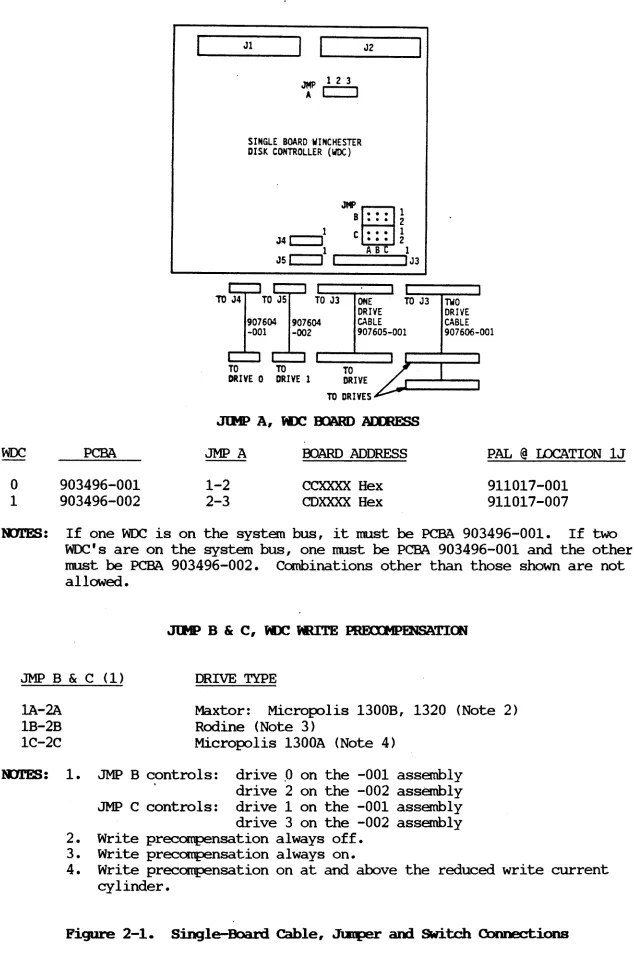
PCBA JMP A OOARD ADDRESS PAL @ IDCATION lJ
o
1
903496-001 903496-002
1-2 2-3
CCXXXX Hex CDXXXX Hex
911017-001 911017-007
l'l11ES: If one WOC is on the system bus, it must be PCBA 903496-001. If two WOC's are on the system bus, one must be PCBA 903496-001 and the other must be PCBA 903496-002. Combinations other than those shown are not allowed.
JMP B & C (1) DRIVE TYPE
lA-2A
1B-2B 1C-2C
Maxtor: Micropolis 1300B, 1320 (Note 2) Rodine (Note 3)
Micropolis 1300A (Note 4)
l'D11!S: 1. JMP B c,ontrols: drive ,0 on the -001 assembly
drive 2 on the -002 assembly JMP C controls: drive 1 on the -001 assembly drive 3 on the -002 assembly 2. Write precampensation always off.
3. Write precampensation always on.
[image:19.816.80.714.3.958.2]4. Write precompensation on at and above the reduced write current cylinder.
Figure 2-1. Single-Board Cable, Jl:Eper and SWitch Connections
2.3.1 Unpacki.ng/Packing Inst.rtx±ions
Each board of the two-board
woe
is shipped in an anti-static bag, inserted be-tween two layers of styrofoam and sealed in a cardboard shiwing Carton. Un-pack thewoe
as follows:1. Prior to accepting the package from the carrier, inspect the ship-ping carton for signs of external damage. Any indication of ex-ternal damage nust be noted on the carrier's shiwing form and reported inmediately to the MBF Sales Office. .
When unpacking each PCBA, set aside the packing materials and shiwing carton for use if it should become necessary to
reship. The PCBA is ESD sensitive.
Proper handling procedures should be used •.
2. With the PCBA shipping carton in its upright position, open the carton and carefully remove the PCBA.
3. Unwrap the PCBA and inspect it for signs of shiwing damage. Im-mediately report any damage to the MBF Sales Office.
2.3.2 Installation Requirements
Install the two-board J
woe
as follows:1.
2.
M8158A
Dangerous voltages exist within the Base Unit of the ID)S IX system. Be sure that
the power is turned off and the power cord
is rE1IDVed before opening the Base Unit
cover.
Shut down the system, turn the Base Unit off and remove the power cord.
To prepare the ~ 2000 system, insert a screwdriver or s~lar
device into the slot at the bottom right-hand side of the Base Unit cover, and push in to disengage the plastic latch. Repeat for the
left-hand latch and remove the cover.
3. To prepare the MAl 3000 system, perform 'the following:
a. Remove the CCA front panel by using a screwdriver to disengage two captive screws at the bottom and then pliling from the bot-tom. If device controller boards, mem:::>ry boards or drives are , to be install~, remove the side panels also.
b. The side panels slide forward for easy removal. It may be helpful to insert the tip of a flat-blade screwdriver between the front flange of the panel and the frane, about midway down the panel; carefully twist the blade to disengage the panel from the frane.
4. Remove the drive cables connected to connectors JO, J1 andJ2 on
the WOC! Adapter PCM (see Figure 2-2 for connector locations).
5. Prepare the replacement
woe
for installation by installing the ap-propriate jumpers and setting the dip switches for thewoe
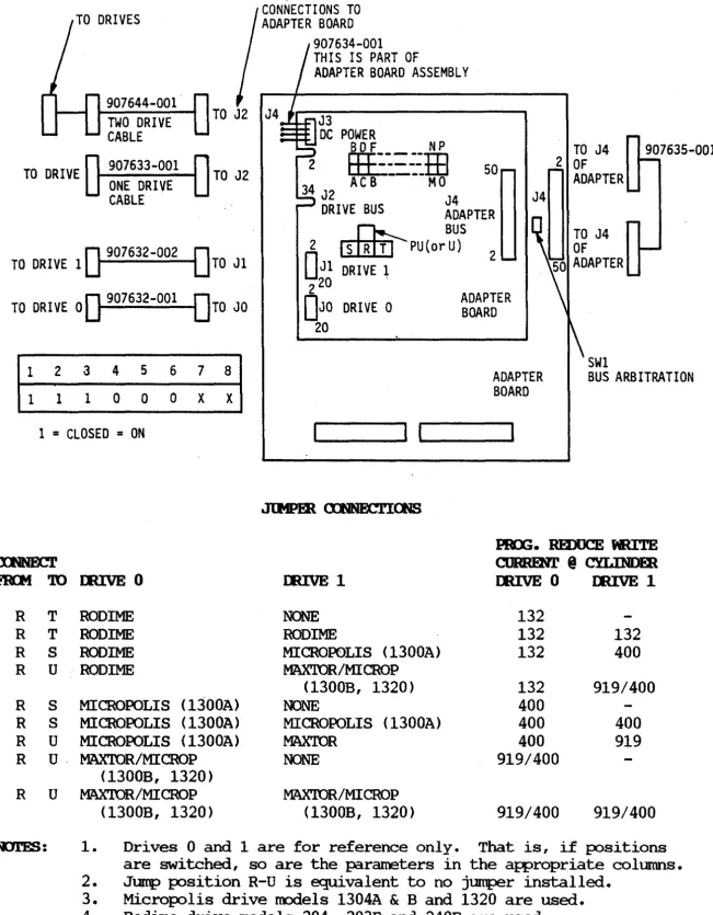
Adapter PCM and Controller PCBA as indicated in Figure 2-2.6. Locate the Adapter PCBA on the Controller PCM in the position shown in Figure 2-2. The four plastic standoffs, (one in each corner of the Adapter PCBA) should line up with the holes in the Controller PCBA. Press down on the corners of the Adapter PCM until the retainers on the standoffs engage the Controller PCM. 7 • Install the power connector into connector J3 of the Adapter PCBA. 8. Install Adapter Drive and Bus cable and the CMB and Drive Bus
cables as specified in Figure 2-2.
9. Replace the Base Unit cover by lowering the cover onto the Base Unit and allowing it to "snap" into place.
10. Reconnect the power cord. Follow the instructions in the
ross
IX System User Guide for operating the host system.TO DRIVES
907644-001 TWO DRIVE CABLE
CONNECTIONS TO ADAPTER BOARD
907634-001 THIS IS PART OF
ADAPTER BOARD ASSEMBLY
J3
DC POWER
...--y-r....l B D F N P
2
TO DRIVE 907633-001 ONE DRIVE CABLE
TO J2 34
EEE:=:.:m
AC B ----MO 50J2 J4
DRIVE BUS ADAPTER
~ BUS
O
907632-0020
TO DRIVE 1 TO Jl
2 []1[[JJ -PU(or U) 2
O
Jl DRIVE 120 ' 2
TO DRIVE 0
0
907632-001 DTO JO DJO DRIVE 0~g~~~ER
201 2 3 4 5 6 7 8 1 1 1 0 0 0 X X
ADAPTER BOARD
SWl
BUS ARBITRATION
1
=
CLOSED=
ON ~----~I I~____ __
~
FIOrI
ro
R T R T R S R U R S R S R U R u·R U
mrES:
M8158A
IIUVE 0 IIUVE 1
RODlME NONE
RODIME RODIME
RODIME MITCROP0LIS (1300A)
RODIME MAXTOR/MITCROP
(1300B, 1320) MITCROPOLIS (1300A) NONE
MITCROPOLIS (1300A) MITCROPOLIS (1300A) MITCROPOLIS (1300A) MAX'IDR
MAX'IDR/MITCROP NONE
(1300B, 1320)
MAX'IDR/MICROP MAX'IDR/MITCRQP (1300B, 1320) (1300B, 1320)
PIU;. REDUCE NUTE
CIJRREN.l' @ CYLINDER
IIUVE 0 IIUVE 1
132
132 132
132 400
132 919/400
400
400 400
400 919
919/400
919/400 919/400
1. Drives 0 and 1 are for reference only. That is, if positions are switched, so are the parameters in the appropriate columns. 2. Jump position R-U is equivalent to no jumper installed.
[image:22.822.90.741.55.890.2]3. Micropolis drive models 1304A
&
Band 1320 are used. 4. Rodime drive models 204, 203E and 240E are used. 5. Maxtor drive models XT1140 and XT1105 are used.Figure 2-2. Two-Board cable, .Jtmller and SWitch Connections
SECTlOO 3
3.1 GEIHW,
This section contains a functional description of the 5-1/4" Winchester Disk Controller (WDC) on three levels: a general block diagram description, a dis-cussion of the system interface characteristics, and a detailed functional description of the WDC circuits.
Figure 3-1 is a functional block diagram of the WDC, showing the relationship of the Adapter section and the Controller section to the circuit elements with which they are involved. As indicated, the basic internal interface is the SCSI (Small Computer System Interface) bus. The a-bit parallel SCSI bus hand-les all communication between the Adapter and the Controller sections.
The MAl 3000 system does not support the two-board WDC.
3.1.1 Mapter Section Functions
The Adapter section provides an intelligent interface between the BOSS IX system 1/0 bus and the SCSI bus internal to the WDC. Primary bus control and interrupt priority are dete~ned by the DMA and Interrupt Arbitration logic, which performs parallel arbitration with up to 16 other device controllers that may be connected to the 1/0 bus. Through this logic and the Control Logic circuit, the WDC responds to a Level 2 interrupt (with 0 being the highest), with a priority level w~ich is lower than that of Memory Refresh, LAN controller or 4~y controller in the system. PAL (Program Array Logic) devices are used in the Arbitration and Control circuits as well as in other circuits such as sequencing, interrupt acknowledge, addressing, status and overall control circuits, to establish logical patterns.
The Address and Bus Control unit determines if the
woe
is being addressed by the host and which port is being used for corrmunication. When the interruptis acknowledged, an a-bit value is placed on the BOSS IX system data bus which is used to create an interrupt vector. The vector is progranmed into latches in the Data Transceiver and Latch circuit before a DMA is initiated. During the DMA cycle, a latch counter drives the BOSS IX system bus address lines and automatically increments the address (on an even word boundary) at the end of . the cycle.
The Control, Vector and status Registers are used for a variety of :purpJses by the host, which include: switching DMA on or off; enabling interrupts on the SCSI bus (disk drive Seek Complete, Command Complete); resetting the WDC;
turning the LED control line on or off; polling the status Register for
woe
status information and making decisions based on the results.~
,
w
~
f
~
•
~
I-!
to
~
~
1
DTC
DTC
INT DATA
SCSI
rpP
I/O BUS
I/O BUS
&CONTR BUS
BUS
DMA
~ .. It... .. &
CONTROL
~BUFF
~US CONTR1
,.
L.. r-'8 t..~
RAM
,.. .,.
..
r-.LOGIC
..
INT
~ ~'8 --.CONTR
ARBIT
v
CONTROL
ADD
&...
I-
BUS
..
..
VECTOR
...
'8...
..
WINCH
...
--.-;... DRIVE
CONTR
&STATUS
...
...
CTRVR
REG.
CONTR
DTC
~..
SCSI ,
~
1 ..
XCVRS
'8 ..BUS
~ENCODE
-'8-' ~
..
J ..;.. P/W 0
& [78-'
XCVRS
'8 ..DECODE
LATCH
&lATA
LATCH
I...---~...I
)L
P BUS
\ I\~ _ _ _ _ ~ I
V
V .The Data and SCSI Bus Transceivers are 8-bit bidirectional registers consist-ing of upper-byte and lower-byte segments. Associated with each segment is a pair of buffers (latches), one for input data and one for output data. The Data Transceivers handle all the
ross
IX system program I/O to and from theWDC, at odd-byte addresses. The Bus Transceivers handle all program I/O to and from the SCSI bus. The input buffers are also used during DMA Read < from
Memory to allow overlapped operations; the output latches buffer data during
DMA Write operations to memory.
3.1.2 Controller Section Functions
The Controller section provides an intelligent interface between the internal SCSI bus and the ST-S06 disk drive interface. The primary control unit in the Controller section is the 8085 Microprocessor. The Microprocessor communi-cates with the other logical elements in the Controller section over its own
(Microprocessor) data bus. The RAM element is a 1K FIFO (first in first out) RAM buffer which transfers DMA data and control signals between the Microproc-essor bus and the SCSI bus. The RAM is protected from overflow or underflow
of data by the Buffer Control circuit. Through the RAM, the Buffer Control
recognizes arbitration logic on the SCSI bus and controls direct memory access
of data out of the FIFO RAM.
Buffer Control also controls the flow of synchronous data to/from the hard disk and the asynchronous SCSI interface, through the dual-port Winchester Controller circuit. The Encoder/Decoder includes the data separator functions needed to convert the MEM read data from the disk into a synchronized clock
and NRZ data stream required by the SCSI bus. The Encoder/Decoder also
per-forms the reverse conversion process; and it incorporates address mark gener-ation and detection logic, as well as the write precampensgener-ation functions re-quired for appropriate disk drive interface.
3.2 SYSTfH I/O INTEBFACE
3.2.1 NlC I/O Addresses
The
ross
IX system assigns address block space in its memory by means of a combination of jumpers and board addresses. The jumpers allow the system to deter:mine whether one or two WDCs are to operate independently on the system I/O bus. The board address defines the exact function the WDC is to perform. The jumper/board address assignments for single-board WDCs are specified in Figure 2-1. The jumper/board address assignments for the two-board WDC are as follows:No. WDCs
1 2
JMP-A 1-2 2-3
Board Address
CCXXXX H CDXXXX H
The address is loaded into the
woe
address registers one byte at a time. Eachbyte nust be acknowledged before the next byte can be loaded. The
sig-nificance of each address is as follows:
o Miress CcoOOl - load I:MA Address Register, HI byte
Miress CCO002 - load r:MA Address Register, MID byte
Address CCO003 - load I:MA Address Register, ID byte
These registers are loaded one byte at a time, with the l' s complement of the
ross
IX system address, right-shifted once.o Address CCO004 - Read Interrupt Vector Register
The BOSS IX system initializes this register before using interrupt. The operation is required only once per J:lv1A; it is not cleared with
Reset. ~. "':)
r , '(,., _,
T ~ ,:):: \} (" c..~
"ff
o Address CCO001 - Read/Write Control Register
0
The Control Register contains control bits 0-5 and status bits 6-7. During a Write operation, only bits 0-5 are significant; during a
Read operation, all eight bits are significant. Individual bits may be turned on or off using a single BSET or BCLR 68000 instruction. The register is cleared with Power On Reset. Th~ significance of the bits is as follows:
Bit Name Read/Write Function
Bit 0 SRST+ R/W Reset the WDC. Bit rrust be maintained
~2
for a minimum of 25 microseconds; logi-cally OR'd with POR and PFD.Bit 1 LED- R/W LED control signal
Bit 2 INTEN+ R/W ENA Oper Compl & Bus Error Interrupts
Bit 3 SEQEN+ R/W Enable Il1A
Bit 4 INTENDO+ R/W ENA Drive 0 Seek Compl Interrupts Bit 5 INTEND1+ R/W ENA Drive 1 Seek Compl Interrupts
Bits 4 and 5 used for buffered seek type drives only; set before issuing Seek command; reset before leaving interrupt
service routine.
Bit 6 INTDO+ R Only Drive 0 Seek Compl Interrupt status Bit 7 INTD1+ R Only Drive 1 Seek campI Interrupt Status
Address CCOOO8 - Host Write to Outplt Register
This address byte is written to by the host dUring I/O data transfer (Information Transfer Phase) Host to Controller) operations.
o Address CC0009 - Read Adapter's status Register
Bit
Bit 0
Bit 1
Bit 2
Bit 3
Bit 4
Bit 5
Bit 6 Bit 7
Name
MYBERR+ PIOINM+
OPCCMP+ PIOUTF+
SRESET+ MSG+ BUSY+ CM)+
Function
Bus Error occurring during WOC's bus mastership
outplt Data Register empty (See Adapter Data Phase and Corrmand Phase)
Operation COIlplete (See Adapter status Phase)
Inplt Data Register Full (See Adapter status Phase and
Message Phase)
SCSI bus in Reset state
SCSI bus in Message Phase
SCSI bus BUSY
SCSI bus in Ccmnand, status or Message Phase
o Address CCOOOA - Host Selects WOC
The host selects the Controller by writing to this address; the presence
of data is indicated by a logical "1". Refer to the paragraphs that follow concerning bus transaction phases.
o Address CCOOOB - Host Read Input Register
During the Information Transfer Phase, the host reads the Input Register
to detennine if the register is full or if data is eX)?eCted. Refer to
the paragraphs that follow concerning bus transaction phases.
o Address CCOOOC - Host Clears Bus Error Latch
The Bus Error signal is latched if it occurs during WOC bus mastership.
All DMA transfers are halted and control of the SCSI bus is released.
The latch remains set TRUE until cleared by the host. . If interrupts are
enabled, a host interrupt is generated.
3.2.2 NlC Transaction
Communication between the BOSS IX system and the WOC is controlled by a six-phase transaction which is initiated by the host. The transaction is
in-itiated when the host selects the
woc.
Upon being selected, thewoe
contendsfor bus mastership with the other ['MAs connected to the host. UJ:X>n winning
the arbitration, the WOC takes control of the SCSI bus and issues appropriate interrupt requests to the host. The host resJ:X>nds accordingly, and the six-phase transaction begins.
The host may cancel a transaction that has started by sending SRST to the WOC;
this will initialize the WOC and put the SCSI bus into its Bus Free status.
The entire six-phase transaction within the
woe
is controlled by a group ofProgranmed Logic Array (PAL) devices.
The detailed operation of the PALs for the single-board WDC is slightly dif-ferent from that for the two-board WDC; consequently, the PAL state diagrams, operation timing diagrams and logic diagrams, as well as parts lists for each WDC are continued in separate FOrtions of this manual: Appendix A for the
single-board WDC, and Appendix B for the two-board
woc.
The following is asummary of the six-phase transaction.
o
am
Free Phase: This Phase occurs when thewoe
is initialized or reset,indicating a NCYl' BUSY condition (status Bit 6, BUSY
=
0=
FALSE). Allcontrol lines are deasserted.
o Selection Phase: Before a conmand is initiated, the ross IX system
IOOnitors status Bit 6, BUSY, for FALSE (high) condition; if high, ross
IX system issues SEL- signal and begins writing OBO- bits to Address
CCOOOA (data present
=
1).o Catmand Phase: With the WDC selected, status Bit 7 (CMD) is asserted;
the I/O line is asserted (high) with status Bit 1 (PIOINM). The ross IX
system sends the WDC a series of Conmand words, byte by byte. The
Com-mand words are defined by the ConCom-mand Description Block (CDB) fo~t to
be described later. Bit 1 (PIOINM) goes TRUE (high) when the Adapter
output Register is empty and FALSE when full. Conmand bytes cannot be
sent via [MA.
o Information Transfer Phase: Depending IIp)n the CDB values, data may be
transferred between the ross IX system and the WDC either via ~ or via
progranmed I/O, as discussed in the paragraphs that follow.
1. SEQEN+ (Control Register Bit 3) TRUE: data transferred via [MA.
Data transfer takes place at a Microprocessor-controlled rate.
2. SEQEN+ FALSE; CMD (status Bit 7) held TRUE (asserted): data is
transferred via progranmed I/O, as follows:
o When PIOINM (status Bit 1) is asserted (Input Buffer full),
host writes data to output Register Address CCOOOB.
o When PIOtJrF (status Bit 3) is asserted (output Buffer full),
host reads data from Input Register Address CCOOOB.
o status Phase: status Phase is entered when CMD (status Bit 7) and
PIOUfF (status Bit 3) and 0Pa:MP <status Bit 2) are asserted. If host
interrupts are enabled (INl'EN, Control Register Bit 2 is TRUE), the host
is interrupted; if not, 0Pa:MP is IOOnitored by the host to determine
coomand completion status. (See paragraph 3.2.3 for a discussion of the
Completion status Bytes.)
o Message Phase: The Message Phase occurs after the status Phase is read.
PlOUfF (status Bit 2), MSG (status Bit 5) and CMD (status Bit 7) are all
asserted. The host reads the Message byte <which is always zero and has
no significance) and causes the
woe
to return to the Bus Free Phase <allcontrol lines deasserted). To initiate another conmand, the WDC must be
again selected and the six-phased transaction is repeated.
3.2.3 Calpletion status Byte
The Completion status Byte indicates the results of the current transaction; it is read by the host during the status Phase. The structure and the Slg-nificance of the CompletiQn Status Byte are as follows:
BYTE/BIT 00
Bits<7 •• 4> Bit<3>
Bit<2> Bit<l>
Bit<O>
3.2.4 ~r Sensing
7 6 5 4 3 2 1
o
Reserved : BUSY : EQUAL: CHECK : Resvd :
Reserved - Always zero
BUSY
woe
is not ready and is unable to accept a corrmand from ross IX system. BUSY is always sent when a CHECK status (Bit 1 set) is returned.EQDAL When set, indicates Search Complete.
CBBCK When set, indicates a
woe
error and that SENSEdata is available. To determine the type of error that
occurred, the host issues a REQUEST SENSE corrmand, which causes the ag:>ropriate Corrmand Error Code. to be issued
(refer to paragraph 3.2.4).
Reserved - Always zero
Setting the CHECK bit in the Completion status Byte causes SENSE data to be made available for return to the ross IX system in response to a REQUEST SENSE Corrmand. BUSY is returned to the host. The SENSE data is saved by the
woe
until requested, and is cleared when the host acknowledges receipt of the CHECK data.In the REQUEST SENSE Corrmand structure, the Number of Blocks field (Byte 04) specifies the number of bytes allocated by the host for returned SENSE.. Byte values of 00 to 03 default to 04.
BYTE/BIT 7 6 5 4 3 2 1 0
00 0 0 0 0 0 0 1 1
01 : Logical Unit No. Reserved
02 Reserved
03 Reserved
04 Number of Bytes
05 Control Byte (Reserved)
3.2.5 Sense Byte structure
The structure and significance of the bits in the SENSE byte which is returned to the ross IX system in resp::>nse to the REQUEST SENSE Conmand is shown below. In the SENSE byte, the Address Valid bit (Byte 00<7» indicates that the Logi-cal Address bytes contain valid information. The Error Class field value
defines whether the error is drive-related (00), data-related (01) or system-related (02).
7 6 5 4 3 2 1
o
BYTE/BIT
00 :AdVal: Error Class Error Code
01 Reserved : (MBB) lDgical Block Address
02 Ipgical Block Address
03 Ipgical Block Address
3.2.6 Error <DIes
3.2.6.1 Class 00 Error Codes
Class 00 Error Codes are drive-related errors. The codes are as follows:
00 NO SENSE 03 WRITE FAULT
01 NO INDEX SIGNAL 04 DRIVE NOr READY 02 NO SEEK <n1PLETE 06 NO TRACK ZERO
3.2.6.2 Class 01 Error Codes
Class 01 Error Codes are (target) data-related errors. The codes are as follows:
10 I.D. CRC ERROR 18 DATA CHECK IN NO R1?rRY IDDE 11 UNCORRECTABLE DATA ERROR 19 ECC ERROR DURING VERIFY 12 I. D. ADDRESS MARK NOr FOUND 1A INTERLEAVE ERROR
13 DATA ADDRESS MARK NOT FOUND 1B NOr ASSIGNED
14 RECORD NOr FOUND 1C UNFORMA'rrED OR BAD FORMAT
ON DRIVE
15 SEEK ERROR 1D SELF TEST FAILED
16 NOT ASSIGNED 1E DEFECTIVE TRACK
(MEDIA ERRORS)
17 NOr ASSIGNED 1F NOr ASSIGNED
3.2.6.3 Class 02 Error Codes
Class 02 Error Codes are systemrrelated errors. The codes are as follows:
M8158A 20 21
22
INVALID cc:t+'JAND
ILLEXl2\L BLOCK ADDRESS NOr ASSIGNED
26-2F
23 24 25 NOT ASSIGNED
3-8
VOLUME 0VERFI.aV BAD ARGUMENT
3.2.7 Power OP /Reset
When power is aFPlied, the WOC enters a 10- to 20-second (10 seconds per
drive) power-up sequence. Once the drive ( s) come ( s) ready, the WOC reads driver parameter infonnation for Track 0, including block size and drive type data. If a Software Reset is received, the power up sequence is the same,
ex-cept the 20-second timeout is reduced to 200 milliseconds, sirice the drives
are assumed to be at speed. The drive parameter infonnation is not read if a
drive is not ready after timeout; instead, a WOC conma.nd nust be issued to
that unit (excluding the TEST UNIT READY conma.nd) to initiate reading other drive parameters.
In a cold start, the WOC recalibrates the head to Track 0 by introducing a
3-Head Offset and verifying a 3-Head Seek back to Track O. The drive parameter
infonnation for that unit is then saved in the
woc.
If the drive is unfonnatted or the fonnat data is not recognized by the
woe,
the WOC causes a "blown fonnat" bit in
ross
IX on board system meI'OClry to beset; the (Power Up) sequence is halted for that unit. If the drive fonnat is
correct, the WOC causes the drive to read the largest block address present,
up through the last cylinder.
The drive is returned to Track 0, stoFPing in selected "zones" in each track
to read the defect count in the zone. These counts are saved in the
woe
andused to establish the location of target blocks on the disk during reads,
writes and seeks.
During the ~eset sequence, the WOC performs a series of self-diagnostics which
render the WOC unavailable for use for about one second after a hardware Reset is sent. Therefore, the Reset line should be used only for initial or
emergency power up, not if the disk system is "lost" or between corrma.nds. Also, if the drive is not fonnatted or-the fonnat is unreadable, the first corrmand after reset (except Request Sense, Test Unit Ready, start/stop, Send Diagnostic or Mode Select) will show an error.
If a SENSE conma.nd is issued, the returned error code will be an error code without the 'address valid' bit (bit 7) set. The controller will NOT allow any operation that READs, WRITEs or IOOves the heads on a drive with a 'blown'
fonnat. Instead, any of the above operations will return an error status and
an error code of 1C. The 1C code indicates that the fonnat on this drive is
bad. The drive must be fonnatted by the WOC to prevent this "blown fonnat"
lockout. If the drive has been fonnatted by a
woe
and an error comes up atreset, the probable cause is the controller being unable to read the disk.
The controller will make another attempt to recover the drive format
informa-tion every time a read/write conma.nd is issued. The 1Ca error is returned
only when the recovery attempt is failed.
3.2.8 Power Down/Power Fail Detect
When the
woe
experiences a power failure, the Power Fail Detect (PFD) line onthe BOSS IX system 1/0 bus is driven TRUE, and the entire
woe
is Reset becausePFD is logically OR'd with Reset. In addition, PFD causes Write Gate Inhibit
to be asserted to prevent a Write glitch on the disk. Since the drive does
not receive PFD, it must be independently capable of detecting a power
fail-ure, so that it can position the heads over the landing zone area and lor
pre-vent erroneous writing.
3.2.9 Disk Drive Formatting
Every disk drive must be fonnatted by the
woe
(or comparable controller)be-fore data can be written to or read from the drive. Fonnatting is initiated
by the Test Unit Ready conmand from the ross IX system; the
woe
responds witha status byte value of 00, or the conmand is repeated until the Check and Busy
bytes are clear. When the 00 status byte is received, the ross IX system
is-sues M:xie Select containing the necessary drive parameters, follow~ by a
Fonnat command to initiate the actual fonnat~ The
woe
fonnats the disk andstores the drive parameters on the disk, so there is no need to repeat this
infonnation to the
woe
with every Reset or Power Up.3.2.10 IDiS IX system to NlC Sequencing
The BOSS IX system (host) to
woe
(controller> sequencing logic is primarilyimplemented in PAL (Prograrme<i U::>gic Array) Sequencers using combinational and sequential machine logic.
state diagrams, timing diagrams, PAL signal listings and the logic diagrams
associated with the single-board
woe
are contained in Appendix A; thoseasso-ciated with the two-board
woe
are contained in Appendix B of this manual.These sources may be used when considering the detailed operation of the
se-quencers. OVerall, the following function~ are involved in BOSS IX system to
woe
sequencing: .o Set and reset SCSI Out:put Buffer Empty status (PIOINM).
o Oirect fetching of data from lower or upper byte of Data Registers for
SCSI controller.
o Unpack ~r and lower status Byte of Data Register.
o Internal Bus Request to ross IX system interface.
o Provide diagnostic features.
BOSS IX system to
woe
sequencing is significantly different when data transferfrom host to controller is via DMA than when transfer is via 1/0 bus. The
following paragraphs summarize the sequencing functions.
3.2.10.1 Output Buffer Empty status
The Output Buffer Empty status bit (PIOINM) is set if the
woe
requests a byteof data and ACKIN has not been sent to acknowledge transfer of data. PIOINM
is reset when ACKIN is set to acknowledge transfer.
3.2.10.2 Direct Fetching of Data
During a data transfer sequence, SEQEN (Control Register bit 3) is used to
distinguish between a I:MA cycle and a prograrrmed I/O cycle. If SEQEN is FALSE
(high), data t:t:ansfer is via prograrrmed I/O; if SEQEN is TRUE (low), q. LMA
cycle with full handshake between ross IX system and WOC is initiated.
Com-mand and status bytes are always transferred by prograrrmed I/O.
3.2.10.3 Unpacking Data Registers
During each cycle of a I:MA WRITE operation, a word is transferred into the
upper and lower bytes of the
woe
Inp..lt Data Register. The Data Register Einptyflags (UDRE
=
Upper; LDRE=
Lower) provide status and data flow steeringfunc-tions into the SASI Output Buffer. The upper byte is fetched before the lower byte.
3.2.10.4 Generating Internal Bus Requests
Generation of an internal bus request with full handshaking with the host through the EBUS interface logic is controlled primarily by the BRQIN signal
in conjunction with PREFE, as follows:
o When a I:MA cycle has been initiated and there has been no new I:MA
re-quest (PREFET and BRQIN- are both TRUE), I:MA is enabled and a bus
re-quest is initiated. The HTC (host to controller) PAL roonitors the I:MA
cycle and causes DRBUS to signal completion, aithough the actual trans-fer of upper and lower byte data is not complete; the HTC PAL continues transferring data until data transfer is complete.
o When the upper byte data transfer is completed, UDRE goes TRUE to enable
lower byte data transfer. At the same time, BRQIN goes FALSE to enable
another I:MA cycle. This interaction results in the possible overlap of
bus request (BRQIN) with the fetching of lower byte data.
3.2.11 NlC to OOSS IX System Sequencing
woe
to BOSS IX system sequencing is similar to BOSS IX system to WOCsequenc-ing, in that the activities are controlled primarily by PAL Sequencers. Refer to the appropriate Appendix for detailed examination of sequencer operation.
OVerall, the following functions are involved with WOC to BOSS IX system se-quencing operations:
o Set and reset SCSI Input Buffer empty status (PIOUTF)
o Set and reset Operation Complete status bit (OPOQMP)
o Direct fetch of data from the SASI Input Buffer into the upper or lower
byte of the Data Registers
.0 Pack and load upper or lower byte of Data Register for transfer to host
roeIOOry
o Internal bus request to BOSS IX system interface
o Provide diagnostic features
woe
to BOSS IX system sequencing is significantly different when data transfer from the controller to host is via DMA than when transfer is via 1/0 bus. The following paragraphs summarize the sequencing functions.3.2.11.1 Input Buffer Empty status
The Input Buffer Empty status bit (PIOUTF) is set if the
woe
requests a byte of data and ACKOur has not been returned to acknowledge host acceptance.PIOUTF is set for [l\1A IOOde, and when ACKOUT- goes TRUE, the host cl~ks data
into the Input Buffer, upper bytes first. PIOUTF is reset when ACKOUT- 1S set, and is polled by the host to determine DMA transfer activity.
3.2.11.2 Operation Complete status
The OPCOMP bit in the Control Register Word is set when the
woe
enters the status Phase and issues the status Completion Byte. The BOSS IX system may accept the completion byte through the status Register, or wait for aninter-rupt if interinter-rupts are enabled.
3.2.11.3 Direct Loading of Data
Direct loading of data into the Input Data Register is accomplished in one of two ways:
o If SEQEN is FALSE, data transfer is via progranmed 1/0; message or data bytes are loaded from the SASI bus into the Lower Input Data Register. Comnand and status bytes are always transferred by progranmed 1/0.
o If SEQUEN is TRUE (low), a DMA cycle with full handshake between the WOC to ross IX system is initiated. Data is transferred from the Input
Buffer, upper byte first. Loading of the lower data byte enables the next bus request; there is no over lap of bus request and loading of data.
3.2.11.4 Generating Internal Bus Requests
In a DMA cycle, an internal bus request (BRQOUT) with full handshaking is gen-erated after roth upper and lower bytes have been loaded into the Input Data Register. The CTH (controller to host) PAL monitors the DMA cycle and causes DRBUS to go FALSE to signal completion, although the actual transfer of data is not complete; the PAL continues transferring data until loading is
com-~~. '
3.2.12 Diagnostic Features
The ross IX system can test the
woe
by appropriate READ/WRITE operations tothe various (I/O data registers, data buffers and data paths through the PAL Sequencers on the board. The testable areas are:
o Interrupt Vector Register
o Control Register
o status Register
o EBUS I/O Data Register
o SCSI Interface I/O Data Buffers
o ~ and Interrupt logic
3.2.12.1 Regis