Conclusion
Protein separations can be achieved by a variety of afRnity techniques, but separations in the chromatography mode are by far the most widely used. Nature deRned an appropriate pathway to highly efRcient separation } utilization of the phenom-enon of the automatic recognition mechanism existing between a given protein and at least one other. By covalently bonding one of the pair onto an inert matrix a theoretically simple separation process can be de-vised. Although these immunoafRnity separations are widely practised today, severe limitations exist, not least of which are cost and instability of the afR n-ity medium when in use. As modern design aids have become commonplace, in conjunction with newer techniques such as the development of combinatorial library arrays, it has proved possible to mimic nature and replace immunoafRnity matrices by speciR -cally designed synthetic ligands. These new ligands not only accurately emulate the exquisite precision of the natural protein}protein interaction mechanisms, but also provide the opportunity to manipulate the ligand structures, thus offering far more efRcient separations than any previously achieved. For a given protein, from whatever source and at any dilution, it is now possible virtually to guarantee that a highly cost-effective and highly efRcient separation pro-cess can be developed for eventual commercial use.
Designed ligand processes have already been ad-opted for several very large biotechnology projects scheduled to manufacture bulk protein
pharmaceut-icals. A mandatory part of any new protein pharma-ceutical process is the acceptance by regulatory authorities of the separation process involved. That synthesized afRnity ligand separation processes have now been fully accepted by the foremost regula-tory authority, the USA’s Food and Drug Administra-tion, conRrms a worldwide acceptance of the power of ligand design technologies.
See Colour Plate 1.
Further Reading
Briefs K-G and Kula M-R (1900) Fast protein chromatogra-phy on analytical and preparative scale using modiRed micro-porous membranes. Chemical Engineering Science47: 141}149.
Burton SJ, Stead CV and Lowe CR (1988) Design and applications of biomimetic anthraquinone dyes.Journal of Chromatography455: 201}216.
Chase HA (1994) PuriRcation of proteins using expanded beds.Trends in Biotechnology12: 296}305.
Dean PDG, Johnson WS and Middle FA (1985)AfTnity Chromatography:A Practical Approach. Oxford: IRL Press.
Jones K (1990) A review of afRnity chromatography. Chromatographia32: 469}480.
Kenny A and Fowell S (1990)Methods in Molecular Biol-ogy:Practical Protein Chemistry. New York: Humana Press.
Kopperschlager G (1994) AfRnity extraction with dye-ligands.Methods in Enzymology228: 121}129. Walker JM and Gaastra W (1987)Techniques in Molecular
Biology. London: Croom Helm.
CENTRIFUGATION
D. N.Taulbee and M.Mercedes Maroto-Valer, University of Kentucky-Center for Applied Energy Research, Lexington, KY, USA
Copyright^ 2000 Academic Press
Introduction
Centrifugation is a mechanical process that utilizes an applied centrifugal forceReld to separate the compo-nents of a mixture according to density and/or particle size. The principles that govern particle be-haviour during centrifugation are intuitively compre-hensible. This may, in part, explain why centrifu-gation is seldom a part of post-secondary science curricula despite the broad range of scientiRc, medical and industrial applications in which this technique
has been employed for well over 100 years. Applica-tions that range from the mundane, industrial-scale dewatering of coalRnes to the provision of an invalu-able tool for biomedical research.
centrifuges were introduced in 1910, further acceler-ating centrifuge development. Svedberg’s invention of the analytical ultracentrifuge in 1923, operating at 10 000 rpm and equipped with transparent observa-tion windows, marked another milestone in centri-fuge technology. In the 1940s, the isolation of theRrst subcellular components by centrifugal techniques not only served to revolutionize our knowledge of the structure, composition and function of intracellular components, but demonstrated the potential of cen-trifugal methods for biomedical research. Although temporarily abandoned in 1943 in favour of a gas-eous diffusion process, industrial-scale gas cen-trifuges were rapidly developed during World War II in an effort to enrich or separate uranium iso-topes. In 1943, Pickels was theRrst to employ a suc-rose-based density gradient to measure particle sedi-mentation rates. Density gradient centrifugation was further reRned in the 1950s by Brakke, who applied the concept to puriRcation and characterization of viruses, and by Anderson and co-workers at Oak Ridge National Laboratory, who designed a series of zonal centrifuge rotors for separation of subcellular particles and viruses. More recent advances have been characterized by signiRcant improvements in materials and equipment and a broadening range of applications.
Today, centrifuges are routinely used in a variety of disciplines ranging from large-scale commercial ap-plications to laboratory-scale scientiRc research. The number of centrifuge designs and conRgurations used in the mineral, petrochemical, chemical, medical, pharmaceutical, municipal/industrial waste, dairy, food, polymer, energy and agricultural industries (to name a few) seem almost as numerous as the applica-tions themselves. An in-depth description of centri-fuge designs and applications is, therefore, well beyond the scope of this treatise. Instead, this article will present the reader with an introduction to the theory of centrifugation, an overview of the various types of centrifugal separations, and a description of selected rotor/centrifuge designs and their more common applications.
Theory
Sedimentation by Gravity
A particle suspended in a liquid medium of lesser density tends to sediment downward due to the force of gravity,Fg. Newton showed that an object is accel-erated by the gravitational force according to the relation:
Fg"mg"m;980 cm s\2 [1]
wheremis the mass of the object andgis the acceler-ation due to gravity.
In an idealized case of a free-falling object being accelerated by gravity in a vacuum, the velocity of the object would exhibit a uniform rate of increase. How-ever, for a real-world case of an object falling through air, or more appropriately for our purposes, settling in a liquid medium, there are two forces that oppose the gravitational force; the buoyancy force, Fb, and thefrictional force,Ff.
Buoyancy force The buoyancy force wasRrst noted by Archimedes, who showed that a particle sus-pended in aSuid experiences an upwards force that is equivalent to the weight of theSuid displaced:
Fb"mMg"VpMg [2]
wheremM is the mass of theSuid medium displaced,
Vp is the volume of the particle ("volume of the dis-placedSuid), andMis the density of the displacedSuid. At pressures up to several bars (1 bar"105Pa), the
buoyancy force in air or other gaseous media can be neglected to aRrst approximation with respect to the net gravitational acceleration experienced by solids or liquids. However, in a liquid medium, the buoy-ancy force is substantial. Since the volume of the settling material is equal to the volume of theSuid being displaced, the net gravitational force experi-enced by the particle is proportional to the differ-ence between the mass of the particle and that of the displaced medium. Thus, assuming gravity sedi-mentation of a spherical particle with radius r and volume of4
3r3, eqn [1] can be rewritten to show the
net gravitational effect,Fg-net:
Fg-net"43r3(p!M)g"43r3(p!M);980 cm s\2
[3]
whereMis the density of the medium (g cm\3);pis
the particle density (g cm\3); and r is the particle
radius (cm).
For those instances in which the medium density is greater than the density of the material in suspension, the net effect is negative, that is, particles would experience a net upward force in such instances and would tend to rise through the medium.
Frictional force, Ff In addition to the buoyancy force, the movement of a particle through a Suid medium is hindered by the viscosity of the medium,, as described for a spherical particle by Stokes’ equa-tion:
where is the viscosity of the medium in poise, P (g cm\1s\1);ris the radius of the particle (cm); and
(dx/dt) is the velocity of the moving particle (cm s\1).
Eqn [4] shows that the frictional force is propor-tional to the particle velocity and its diameter. At low velocities and pressures, the frictional force is again negligible in a gas. However, at higher velocities, even in gases, this force becomes substantial, combining with the buoyancy force eventually to exactly oppose the gravitational force, resulting in no further acceler-ation of the particle. This condition is known as the limiting or terminal velocity. Mathematically, the conditions for attaining terminal velocity are met when:
Fg"Fb#Ff [5]
The above discussion would imply that with suf-Rcient time completely pure phases can be obtained by gravity sedimentation alone. While this may be true for the sedimentation of large particles in a me-dium with a signiRcantly higher or lower density than the particle, this is not the case for smaller particles, which are impacted by diffusional forces that ultimately limit the separation efRciency as well as to other nonideality effects (see below).
Diffusion Random Brownian motion results in the net movement of solute or suspended particles from regions of higher concentration to regions of lower concentration, a process called diffusion. Thus, diffusion works in opposition to centrifu-gal sedimentation, which tends to concentrate par-ticles. The rate of diffusion of a particle is given by Fick’s law:
dP/dt"!DA(dP/dx) [6]
where D is the diffusion coefRcient which varies for each solute and particle; A is the cross-sectional area through which the particle dif-fuses; and dP/dx is the particle concentration gradient.
The precise impact of diffusion can be dif-Rcult and cumbersome to calculate for complex sys-tems. It is often sufRcient to keep in mind that the rate of diffusion is generally more pronounced for smaller particles than for larger ones, it increases with temperature, and its effects are lessened by higher centrifugal forces.
Aside from theoretical considerations, in a more practical sense, the time required for the settling of small to medium size particles in a gravitationalReld is often prohibitive. Additional obstacles to obtaining pure phases during gravity settling can also arise from
attractive forces between the particles being separ-ated and/or the medium in which they are suspended. Often, gravitational force alone is insufRcient to provide the minimum force necessary to disrupt such attractions. The use of centrifugal settling addresses the shortcomings of gravity settling by shortening the time required for sample recovery at a given purity, providing a greater force for disrupting particle/ par-ticle or parpar-ticle/media interactions and, within limits, lessening the detrimental effects of diffusion.
Sedimentation in a Centrifugal Field
A particle moving in a circular path continuously experiences acentrifugal force,Fc. This force acts in
the plane described by the circular path and is di-rected away from the axis of rotation. The centrifugal force may be expressed as:
Fc"ma"m2x [7]
wheremis the particle mass (g);ais the acceleration (cm s\2); is the angular velocity (radians
s\1"2rpm/60); and x is the radial distance from
the axis of rotation to the particle (cm).
Thus, centrifugal force is proportional to the square of the angular velocity and to the radial dis-tance from the axis of rotation. The force generated during centrifugation can be compared to the gravi-tational force by therelative centrifugal force, RCF, often referred to as thegforce:
RCF"Fc/Fg"(m2x)/(mg)"(2x)/g [8]
Convertingto rpm and substituting values for the acceleration due to gravity, eqn [8] can be rewritten in a more convenient form as:
RCF"1.119;10\5(rpm)2x [9]
While RCF is a ratio, and therefore unitless, it is frequently expressed in units of g to indicate the number of times that the force of the applied centrifu-galReld is greater than the force of gravity.
The forces acting on a particle suspended in a liquid medium in a centrifugalReld are illustrated in
Figure 1 Forces acting on a particle in a centrifugal field:Fb,
buoyancy;Ff, frictional;Fc, centrifugal; andFg, gravitational.
forces equals the centrifugal force:
Fc"Fb#Ff [10]
Substituting eqns [2], [4] and [7] into eqn [10] gives:
m2x"VPM2x#6r(dx/dt) [11]
Assuming a spherical particle and substituting4 3r3for
volume gives:
(43r3)P2x"(43r3)M2x#6r(dx/dt) [12]
Then solving for dx/dt:
dx/dt"[2r2(P!M)2x]/9 [13]
Eqn [13] is more commonly expressed in terms of particle velocity,v, and particle diameter,d:
v"(d2(P!M)2x)/18) [14]
Eqn [14] may be integrated to determine the time required for a particle to traverse a radial distance fromx0tox1:
t"[18/(d2(P!M)2)] ln (x1/x0) [15]
wherex0is the initial position of the particle andx1is theRnal position of the particle.
While modiRcations can be made to eqns [13]}[15] to account for speciRc rotor design, liquid}liquid, density-gradient separations, etc., these equations de-scribe the relative impact of the more signiRcant
para-meters that govern settling velocity. They show that the sedimentation rate (i.e. limiting velocity) of a par-ticle in a centrifugalReld:
E increases as the square of the particle diameter and rotor speed, i.e. doubling the speed or particle diameter will lessen the run time by a factor of four;
E increases proportionally with distance from the axis or rotation; and
E is inversely related to the viscosity of the carrier medium.
These are the fundamental premises that a practi-tioner must know in order to develop a rational approach to centrifugal separation.
Sedimentation Coef\cient
Since the terms r, P, M and as given in eqns [13]}[15] are constant for a given particle in a homogeneous medium, the sedimentation rate, dx/dt, is proportional to2x. This proportionality is
often expressed in terms of the sedimentation coef-Rcient,S, which is simply a measure of the sedimenta-tion velocity per unit of centrifugal force. For a given set of run conditions, the sedimentation coefR c-ient,Sr, may be calculated as:
Sr"(dx/dt)/(2x)"2r2(P!M)/9 [16]
The sedimentation coefRcient, S, has the dimen-sions of seconds and is expressed in Svedberg units equal to 10\13s. Its value is dependent on the particle
being separated, the centrifugal force and the proper-ties of the sedimentation medium. While adequate for a given set of run conditions, it is sometimes useful to compare sedimentation coefRcients obtained un-der differing conditions and/or sedimentation media by reference to the behaviour of the particle in water at 203C,S20,w:
S20,w"ST,MT,M(P!20,w)/20,w(P!T,M) [17]
where the subscripts T and M denote the experi-mental temperature and medium, respectively.
Rotor Ef\ciency
The time required for a particle to traverse a rotor is known as the pelleting efRciency or k-factor. The
rotor and are useful for comparing sedimentation times for different rotors. The k-factor is derived from the equation:
k"ln (rmax!rmin);1013/(36002)
"2.53;1011;ln (rmax!rmin)/rpm2 [18]
wherermaxandrminare the maximum and minimum distances from the centrifugal axis, respectively.
Eqn [18] shows that the lower the k-factor, the shorter the time required for pelleting. If the sedi-mentation coefRcient of a particle is known, then the rotor k-factor can also be calculated from the relation:
k"TS [19]
where T is the time in hours required for pelleting and S is the sedimentation coefRcient in Svedberg units.
Whenkis known (normally provided by the manu-facturer), then eqn [19] may be rearranged to calcu-late the minimum run time required for particle pelleting.
For runs conducted at less than the maximum rated rotor speed, the k-factor may be adjusted according to:
kadj"k(rpmmax/rpmact)2 [20]
where rpmmax and rpmact are the maximum rated
rotor speed and actual run speed, respectively.
k-Factors are also useful when switching from a ro-tor with a known pelleting time,t1, to a second rotor of differing geometry by solving for t2 in the relation:
t1/t2"k1/k2 [21]
where t1, t2, k1 and k2 are the pelleting times and
k-factors for rotors 1 and 2, respectively.
Deviation from Ideal Behaviour
Eqns [13] and [14] showed the relative impact on settling velocity of the more important and control-lable experimental parameters. However, there are other effects that are more difRcult to char-acterize and which can result in signiRcant deviations from the settling velocities predicted by these equa-tions. The most common of these effects occurs when the particles are nonspherical, as these equa-tions are derived from Stokes’ equation assuming spherical particles. For nonspherical particles, eqns [13] and [14] may be modiRed with a correction
term,. In Stokes’ equation, the term 6rdescribes the frictional coefTcient, f0, for a spherical par-ticle. The correction term,, is calculated as the ratio of the frictional resistance,f, encountered by a par-ticle of nonspherical geometry to that encountered by a sphere of the same volume, or:
"f/f0"f/6r [22] The equation describing the terminal velocity for nonspherical particles in a centrifugal Reld may be rewritten as:
dx/dt"[d2
e(P!M)2x]/18 [23]
where de is the diameter of a sphere whose volume equals that of the sedimenting particle (de/2 is the Stokes radius).
The net result of this modiRcation is that non-spherical particles are predicted to sediment more slowly, which is a more accurate depiction of their real-world behaviour.
In addition to deviations from spherical-particle geometry, there are other effects that can lead to departure from predicted behaviour (nonideality) during sedimentation. For example, many biological particles interact with the medium via hydration, the extreme case being for those particles with osmotic properties, which can result in drastic changes in particle density and, in turn, sedimentation coef-Rcients. Interparticle attractions, e.g. charge or hy-drophobic effects, may increase the effective viscosity of the medium. In more severe cases such attractions can lead to poor separations where the centrifugal energy is insufRcient to disrupt the attractions between particles that are targeted for separation. This latter effect is aggravated by the fact that the larger or denser particle will lead as the particle pair migrates toward the rotor wall while the smaller or lighter attached particle follows in its wake, and therefore experiences less frictional drag. Particles may also concentrate locally to increase the effective medium density, or form aggregates that yield complicated sedimentation patterns. Be-cause of such deviations from ideal behaviour, equiv-alent sedimentation coefRcients, SH, deRned as the sedimentation coefRcient of an ideal spherical particle, are often reported for a given set of experi-mental conditions.
Filtration
Figure 2 Basket filtration centrifuge.
or the pressure generated by the centrifugal force is substituted for the gravitational or differential-pressure terms. AsRltration is an extensively charac-terizedReld of study, a description of which is beyond the scope of this article, it is recommended that the reader refer to the literature for an in-depth math-ematical discussion of both conventional and centri-fugalRltration. However, a brief summary of some of the more important parameters that governSow velo-city and pressure drop during centrifugal Rltration follow. A simple basket centrifuge is shown schemati-cally in Figure 2. Assuming a constant height of liquid within the basket, the velocity of theRltrate,u, through a given cake thickness, dl, is given by the relation:
u"[1/(2rH)]dV/dt"[1/a](!dP/dl) [24]
whereH is the basket height or length (2rH is the cross-sectional area of the Rlter); r is the distance from the axis of rotation to the inner cake surface; dV/dtis the volume ofRltrate passing in time dt;ais the speciRc resistance of the cake;is the viscosity of the Rltrate; dP is the pressure drop across a given thickness of Rlter cake; and dl is a given cake thickness.
The velocity of the Rltrate through the cake and underlyingRlter is thus proportional to the volume of Rltrate Sow or the pressure differential across the Rlter cake, and inversely related to the surface area of the Rlter, Rltrate viscosity and cake resistance. Eqn [24] may be rearranged and integrated to deter-mine the total pressure drop across the cake at timet:
!P"(a/2H) dV/dtln (r/r) [25]
whereris the distance from the axis of rotation to the outer cake surface.
If the resistance of the Rlter is negligible, P is equivalent to the centrifugal pressure. A parameter that is widely used to characterize the performance of Rltration equipment is the drainage number:
Drainage number"dM(G)1/2/ [26]
wheredM is the mean particle diameter (m);Gis the centrifugal force ("2r/g), where r is the largest
radius for a variable radius screen; andis theRltrate viscosity (m2s\1). Higher drainage numbers
corres-pond to more rapid drainage.
Types of Separation
One approach to classify centrifugal separations is according to the phase of the medium and the phase of the material to be puriRed, e.g. gas}gas, liquid}liquid or liquid}solid. Centrifugal separations of gas-phase materials are conducted in continuous mode only, while liquid}liquid and liquid}solid may be conducted in batch, semi-batch, or continuous modes. Gas-phase separations are very important in certain applications, particularly uranium isotope en-richment, but are highly specialized and not widely used. For space considerations, gas-phase separations are omitted from this discussion. Likewise, while liquid}liquid and even liquid}liquid}solid separ-ations are common, discussion of the separation of immiscible liquids is, for the most part, limited to the discussion of centrifuge types in subsequent sections. SufRce it to say that the principles and ap-proaches discussed in relation to liquid}solid separ-ations generally apply to liquid}liquid separations. That is, small droplets of a liquid dispersed in a sec-ond, immiscible liquid will behave like solid particles settling through a liquid medium until the droplets sediment and coalesce, after which the methods to remove the separated liquids from the centrifuge usu-ally differ from those used for solids removal.
Figure 3 Differential sedimentation or pelleting. (Courtesy of Beckman Instruments, Inc.)
The types of separation to be discussed focus on the separation of solids from liquid media using any of the recovery modes described above. Discussion of simpler batch-mode operation is emphasized for sim-plicity. Three primary types of centrifugal separations are discussed: differential sedimentation, density gradient and Rltration, with density gradient being further divided into rate-zonal and isopycnic (in isopycnic separations, particles sediment until they attain a position in the gradient at which the medium density is equal to their own).
Differential Sedimentation
As previously shown by the equations describing sedi-mentation (eqns [13] and [14]), larger and/or denser particles will sediment more rapidly in a centrifugal forceReld and will thus pellet onto the outer wall of the rotor faster than smaller or lighter particles. Most applications are based on this difference in be-haviour, referred to as differential sedimentation orpelleting. In a simple batch-mode pelleting separ-ation, a sample mixture called the homogenate (im-miscible liquids or solid suspensions) is placed into a centrifuge container or rotor, and separated into two fractions as depicted in Figure 3. The un-sedimented material is termed the supernatant and the sedimented material is thepellet. This approach works well when the objective is to pellet all the solid particles or to clarify the liquid. Such separations are also commonly used in the laboratory for ‘quick and dirty’ separations or where the objective is to enrich or clarify materials for subsequent analysis.
Obtaining high purity separations by differen-tial sedimentation is more difRcult. With respect
to separating particles of similar density according to size (classiRcation), an approximate order of mag-nitude difference in mass between the particles is needed for differential sedimentation to be effective. The main disadvantage of separating a homogenate in batch mode is that the centrifugalReld required to pellet the larger or denser particles that are initially nearer the axis of rotation is capable of pelleting smaller or lighter particles initially closer to the outer wall (Figure 3). Product purity or recovery may be improved by either recentrifuging the supernatant to obtain more pellet, or by resuspending the pellet and recentrifuging to obtain higher purity. When purity is the primary concern, this approach can still be used as a preparatory step to provide an enriched fraction for subsequent puriRcation. However, a more efRcient one-step approach is to layer the sample mixture on top of the preloaded medium. Stopping the run before the lighter or smaller con-taminant particles reach the rotor wall allows them to be decanted with the supernatant. An alternative is to use a continuous-feed rotor in which the sample mixture is introduced near the axis of rotation and the supernatant, containing the smaller or lighter unsedimented particles, is continuously discharged. A more efRcient approach is to layer or feed the sample to the top of a preloaded density gradient (see below).
Density Gradient Centrifugation (DGC)
DGC, developed in the 1950s, also relies on dif-ferential sedimentation behaviour to separate sample components, but compensates for some of the disad-vantages of homogeneous media and also allows for the simultaneous separation of multicomponent mix-tures. This is accomplished by the use of a density gradient, i.e. a liquid medium that increases in density from the layers nearest the axis of rotation to those farthest away. As will be discussed, this is achieved through variation in the concentration of an aqueous solute, or other gradient material, across the rotor. With minimal precautions, density gradients are sur-prisingly stable for extended periods, even with the rotor stopped. DGC separations are more extensively used for smaller-scale research applications in con-trast to large-scale pelleting separations that are more common to industrial applications. DGC may be con-ducted as either rate or isopycnic separations.
Figure 4 Rate-zonal separation in a swinging-bucket rotor. (Courtesy of Beckman Instruments, Inc.)
Figure 5 Isopycnic separation with a self-generating gradient. (Courtesy of Beckman Instruments, Inc.)
separation, larger particles sediment more rapidly, just as in a pelleting run. Also similar to a pelleting run, the maximum medium density is lower than the density of the particles being processed. However, unlike pelleting runs, the run must be stopped before particles reach the bottom of the tube or rotor wall, otherwise all sample components will simply sedi-ment to the pellet.
Rate orsetting velocityseparations may be conduc-ted with a homogeneous medium in batch or semi-batch mode. However, the use of density-gradient media offers several advantages. The steep gradi-ent beneath the layer of sample suppresses premature sedimentation as well as convection currents in the liquid column, both of which lower the separation efRciency. In addition, the continuous increase in density, often accompanied by an increase in viscosity across the rotor, serves to slow the faster-moving particles and provide better resolution in the sample componentbands. Increasing-viscosity gradients also lessen diffusional effects, though this ad-vantage may be offset by an increase in the re-quired run time. Rate-zonal separations are well suited for mixtures of particles of similar density that exhibit two or more well-deRned modes of size distri-bution. However, owing to the additional steps and equipment required for DGC as opposed to pelleting, DGC separations are more commonly used to separ-ate particle mixtures based on a parameter other than size, e.g. density.
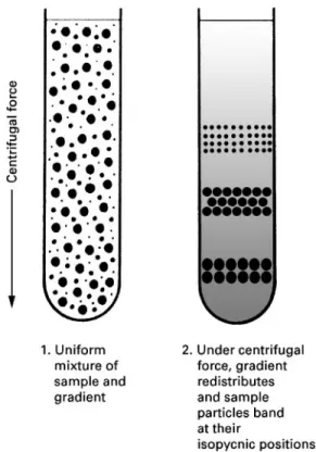
Isopycnic separations These separations, which are based on differences in particle densities, are
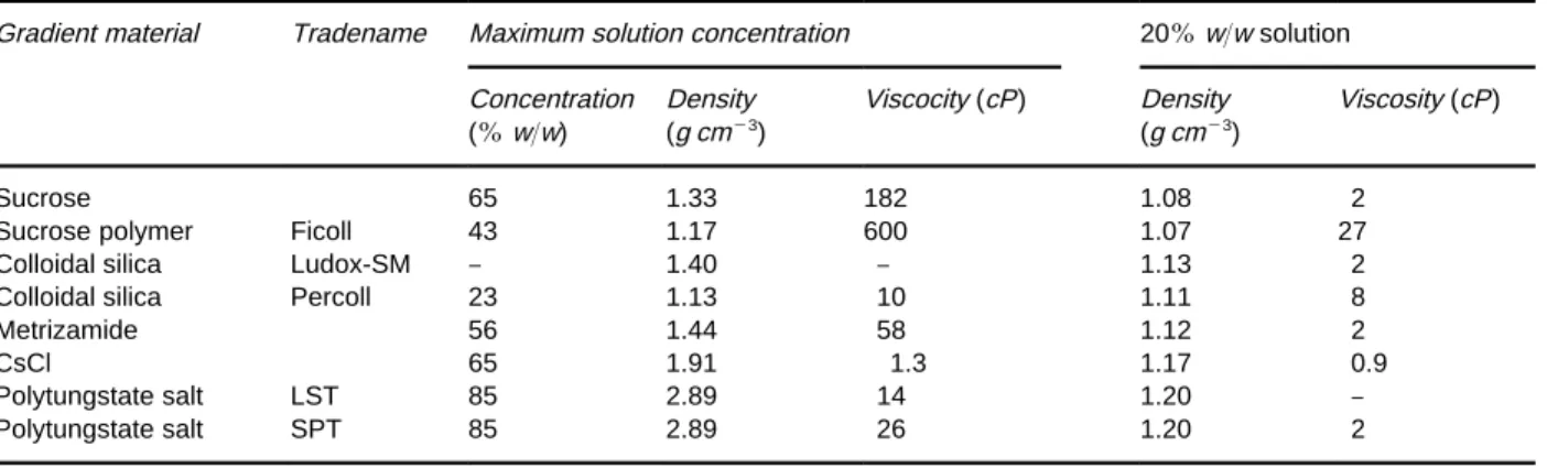
Table 1 Physical properties of gradient materials in aqueous solutions at 203C (from Sheeler, 1981)
Gradient material Tradename Maximum solution concentration 20%w/w solution
Concentration (%w/w)
Density (g cm\3)
Viscocity (cP) Density (g cm\3)
Viscosity (cP)
Sucrose 65 1.33 182 1.08 2
Sucrose polymer Ficoll 43 1.17 600 1.07 27
Colloidal silica Ludox-SM } 1.40 } 1.13 2
Colloidal silica Percoll 23 1.13 10 1.11 8
Metrizamide 56 1.44 58 1.12 2
CsCl 65 1.91 1.3 1.17 0.9
Polytungstate salt LST 85 2.89 14 1.20 }
Polytungstate salt SPT 85 2.89 26 1.20 2
centrifugal speeds. This is achieved by routing the solutions to the rotor wall through veins in the central core. When suchself-generatinggradients are used, it is not necessary that the sample be layered on top of the solution but instead it may be mixed with the medium prior to loading (Figure 5). While self-generating gradients offer greater simplicity, they often require a signiRcant increase in run time. For instance, though the advent of vertical tubes, faster centrifugal speeds, and overspeeding techniques have reduced run times to about one-third of those re-quired only a few years ago, runs of 3 to 12 h are still typical for DNA banding experiments.
Isopycnic separation is a more powerful separation tool than rate-zonal separation in the sense that a gen-erally greater number of particle types can be re-solved. However, rate runs may still be preferred for separating large and/or fragile particles, since shorter run times and lower centrifugal forces are used. Run duration is crucial for a rate separation, whereas isopycnic runs simply require a minimum time for the particles to reach a stationary state. It is sometimes useful to conduct a two-dimensional separation in which, for instance, a rate-zonal run generates frac-tions of particles with similarSvalues that are further fractionated according to density in an isopycnic sep-aration. The reverse process can also be performed to yield particles of similar density but different particle size distributions.
Gradient materials The selection of an appropriate gradient material is an important consideration as the gradient properties must be compatible with the sep-aration objectives. The desired properties of an ideal gradient material, as set forth by GrifRth and by Ridge, are summarized below.
The ideal gradient material should:
E span a density range sufRcient to permit separ-ation of the particles of interest without overstress-ing the rotor;
E be stable in solution;
E be inert towards the fractionated materials, includ-ing biological activity;
E exert the minimum osmotic effect, ionic strength and pH;
E be removable from the product;
E be readily available and either inexpensive or easily recyclable;
E be sterilizable. It should not:
E generate a prohibitively high viscosity;
E interfere with the assay technique (e.g. absorb UV or visible light);
E be corrosive; or
E generateSammable or toxic aerosols.
From this list of properties, it is apparent that no single ideal gradient material exists, as each separ-ation problem imposes its own set of requirements. Rather, selection can only be made after a careful evaluation of the gradient properties with respect to the requirements imposed by the separation to be conducted. The list of materials that have been used for gradient formation is extensive with examples of the more commonly used materials along with selected properties listed inTable 1.
With respect to biological inertness and low viscos-ity, the ideal aqueous gradient material is deuterium oxide (D2O). However, D2O is expensive and has
a relatively low maximum density (1.11 g cm\3).
Sucrose was used in the pioneering density-gradient work of Brakke and, due to its low cost, transpar-ency, ready availability and nontoxic nature, is still the most widely used. Densities to 1.33 g cm\3can be
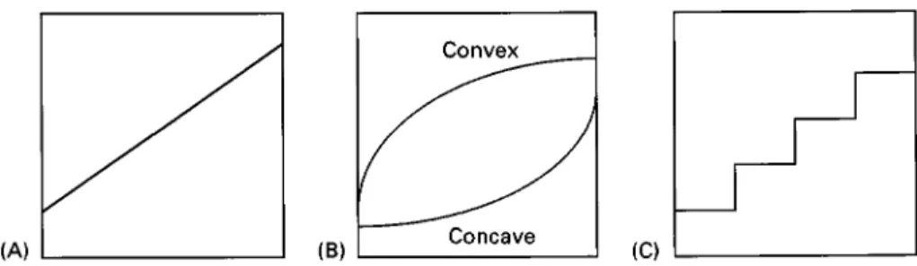
Figure 6 Gradient shapes: (A) linear; (B) exponential; and (C) isokinetic. compensate for these deRciencies, but use of these
sugars has disadvantages including higher viscosity and lower maximum densities. Polysaccharides also have a low osmotic pressure, but again are more viscous than sucrose solutions of equal density and may induce aggregation of the suspended sample via charge interactions.
Silica sols (e.g. Ludox2+and Percoll2+), also called colloidal silica, are prepared from small silica par-ticles in mildly alkaline solution. They provide low viscosities and osmotic pressures, even at high densit-ies, and are transparent and inexpensive. Silica sols provide densities to 1.40 g cm\3. Their disadvantages
include a tendency to gel at pH(7 and problems in complete removal from the sample. Percoll2+, pre-pared by coating the silica particles with a polymer, eliminates the gelling problem and provides low vis-cosity, low osmotic pressure solutions, greater stabil-ity at low pH, and densities to 1.21 g cm\3. However,
this material is relatively expensive and removal from the sample can be a problem.
Salts are used to generate very high density aqueous solutions. Cesium chloride is by far the most widely used of this class. CsCl solutions can reach densities of&1.9 g cm\3at saturation while providing a very
low viscosity at lower concentrations. Although ex-pensive, CsCl can be readily recovered and puriRed. CsCl solutions also have a high osmotic pressure and are corrosive, though the titanium rotors generally used with this solute are relatively resistant. CsCl gradients are commonly used in applications ranging from the separation of viruses and dense cellular macromolecules such as DNA, to geological poly-mers found in coal or oil shale. Other salts that have been used to produce high density gradients include sodium bromide, sodium iodide, cesium bromide, cesium sulfate, cesium formate, cesium triS uoro-acetate, rubidium bromide and rubidium chloride. Though expensive, tungstate polymers such as so-dium polytungstate (SPT) and lithium heteropolytun-gstate (LST) have recently been used to generate aqueous gradients well over 2.5 g cm\3. Applications
for these materials include the separation of graphitic carbon and mineral components fromSy ash. When using such high density salt solutions, the user should be aware that at high concentration, salts may pre-cipitate on the rotor wall, thereby generating high point densities and the potential for catastrophic ro-tor failure.
For nonaqueous gradients, organic liquids such as toluene, methanol or kerosene may be blended to attain gradient densities lower than that of water (1.0 g cm\3). Of these, methanol presents an
addi-tional advantage of being water-soluble, thereby allowing gradients to be formed from a combination of the two. On the other end of the density scale, halogenated liquids such as diodomethane, bromo-form and tetrabromoethane can be used to prepare very dense solutions over 2.8 g cm\3. Problems
asso-ciated withSammability, toxicity and attack of trans-fer lines and seals must be considered when using these materials.
Gradient formation and shape Gradient shape re-fers to the density proRle across the tube or rotor as a function of gradient volume (Figure 6). Its choice is important as it governs the sedimentation rate in both rate and isopycnic experiments as well as the terminal position in isopycnic runs.
In a linear gradient, density increases linearly with distance from the axis of rotation (Figure 6A), and for cylindrical swing-out rotors, with increasing gradient volume as well. In an exponential gradient, the density increases or decreases exponentially across the rotor, producing convex or concave shapes, respectively, when plotted as a function of radial distance (Figure 6B). Isokinetic gradients are designed to produce a uniform sedimentation velocity throughout the gradient by counterbalancing the in-crease in centrifugal force particles experience as they traverse the gradient with an increase in the density and viscosity of the medium. Such gradients are often used in analytical rotors to study sedimentation be-haviour. Simple linear sucrose gradients loaded in a swinging rotor provide a near isokinetic gradient.
Various methods are used to form gradients. The simplest approach is to form the gradientin situ, i.e. self-generating, by mixing the sample with a single-density medium prior to loading, then forming the gradient at high centrifugal speeds. While this is the simplest approach, higher speeds and longer run times are often required. Step gradients are also easily formed by simply pumping targeted volumes of suc-cessively denser solutions to the rotor wall. Inexpen-sive peristaltic pumps provide the simplest means of loading step gradients. The simplest liner-gradient generators consist of two equivalent cross-section cy-linders that contain an initial and a limiting solution, respectively. The chambers are interconnected at the base with liquid from the limiting solution being drawn into and mixed with the initial solution as material from the initial-solution chamber is loaded. Exponential gradient generators are similar except that the cross-sectional area of one of the chambers changes in a predetermined manner as the chambers are depleted, thereby changing the relative volume contributed from the two chambers with time. More sophisticated gradient pumps are available including mechanical pumps that use cams to mix variable amounts of low and a high density solution prior to loading or programmable pumps, e.g. a liquid chromatograph pump, to generate the targeted gradi-ent curve shape.
Several approaches are used to analyse and/or frac-tionate the rotor efSuent. The simplest is to split the gradient into fractions according to volume, then subsequently analyse each fraction by chemical (den-sity, absorbance, refractive index, Suorescence) or scintillation methods. However, this approach may be somewhat limited in resolution if the collected fractions are large, and thus represent a wider range in density. An alternative approach is to route the efSuent through one or more in-line, low volume Sow cells to monitor the gradient properties.
Auto-mated fractionators that select cut points and auto-matically switch collection vessels rely on such in-line detectors.
Analytical Centrifugation
This is the only type of centrifugal separation in which the primary objective is not to purify or de-water one or more of the feed components. Rather, this method is used to monitor particle sedimentation behaviour. Analytical centrifugation is used to char-acterize particle properties such as molecular weight, diffusion and sedimentation coefRcients, buoyancy density, etc. The critical component in this technique is the addition of a transparent window, e.g. quartz or sapphire, to the centrifuge rotor to permit in situ
optical measurements. Sample movement is typically monitored by UV absorption or refractive index dur-ing high speed separations in ultracentrifuges. Experi-ments are conducted in batch mode using very small sample volumes, as low as 5L for some rotors. Two classes of experiments are conducted in an analytical ultracentrifugation}sedimentation velocity and sedi-mentation equilibrium}anlogous to rate and isopyc-nic experiments in preparative ultracentrifugation. Of these, sedimentation velocity is the more common. Analytical centrifugation is less common today than in the 1950s when this was the principal method for molecular weight determinations (1}10 kDa). How-ever, the method is still used, primarily in biological applications, for studying phenomena such as interac-tions between macromolecules and ligand-induced binding events. More recently, this technique has experienced somewhat of a renaissance in drug dis-covery applications.
Continuous Centrifugation
The parameters of primary concern for continuous separations are centrifugal force andSow rate. These parameters must be carefully controlled to provide sufRcient time for solid or denser liquids to sedi-ment before being carried out with the supernatant, but not so long as effectively to under utilize the throughput capacity of the rotor. The parameters controlling particle sedimentation are the same in continuous-Sow as in batch-mode separations. Therefore, the maximum Sow rate that can be util-ized in a speciRc rotor at a given speed may be estimated by using eqn [15] to determine the time required for a given particle to traverse the radial distance from the rotor exit,re, and to the outer rotor wall,rmax. With information on liquid volume within the rotor and assuming laminarSow of liquid from the entry to the exit port(s), theSow rate can then be adjusted to provide this minimum residence time. The calculation of the minimum residence time is simpler if the rotor k-factor and the particle sedimentation coefRcient are known, in which case the min-imum residence time required for pelleting can be calculated from eqn [18] (i.e.T"k/S, where Tis in hours).
Continuous centrifugation is used extensively in industrial applications, where large sample through-put and recovery is more common. However, laborat-ory-scale continuous-feed applications are also mon, particularly in semi-batch mode where the com-ponent to be isolated is present at low concentrations. Owing to the variety of continuous-Sow conR gura-tions that are available, further discussion of this approach is to be found in the section on centrifugal equipment below.
Filtration
Filtration is a mechanical means of separating solids from a liquid suspension via a porous medium or screen that permits the liquid to pass while retaining the solids. Similar to conventionalRltration, achieved via a differential pressure across a Rlter, centrifu-gal Rltration is driven by the pressure exerted by a liquid medium within a centrifugal forceReld. Op-posing the centrifugal pressure is the combined resist-ance of the porous medium andRlter cake. Centrifu-gal Rlters are commonly used to remove or recover coarse and crystalline solids from aSuid slurry, often followed by a rinse cycle to purify the solids and remove the residual mother liquor. In this technique, a sample slurry is fed to the rotor with the centrifugal pressure forcing the carrier liquid through a cylin-drical screen or other permeable medium positioned around the outer wall to retain the solids or Tlter cake. The Rlter cake may be dried by shutting off the slurry feed and spinning the solids to attain
resid-ual moisture contents lower than generally provided by Rlter presses or vacuumRlters. Most centrifugal Rltration applications are typically conducted in con-tinuous or semi-batch mode in which the liquids passing theRlter are continuously discharged and the Rlter cake is continuously discharged or recovered post run. Perhaps the most widely used example of centrifugal Rltration is the spin cycle in domestic washing machines.
CentrifugalRltration is a complex process that is dependent on a number of parameters including liquid viscosity, cake thickness, centrifugal force, screen area and, importantly, the size and packing characteristics of the particles themselves. Centrifugal Rltration may be conducted in batch, semi-batch or continuous mode. While traditional industrial ap-plications commonly use centrifugalRltration to re-cover solid materials with reduced moisture contents, many laboratory-scale spin Rlters, particularly in a test-tube conRguration, are available. This tech-nique is generally not amenable to broad generaliz-ations and is, therefore, best approached on a case-by-case basis.
Centrifugal Equipment
Centrifuges and rotors are commercially available in literally hundreds of shapes, sizes and conRgurations. They range from small laboratory-scale units equip-ped with capillary tubes, operating at speeds in excess of 100 000 rpm or forces approaching 1 000 000gto large industrial decanters that may continuously pro-cess up to 300 000 L h\1. The primary rotor or
cen-trifuge selection criteria must centre on the objective for conducting the separation. Parameters such as batch versus continuous; required centrifugal force and purity; throughput; the number of components to be recovered; sample toxicity/corrosiveness; time; cost; available space; noise tolerances, and so forth must be considered when selecting the appropriate centrifuge/rotor for a given application.
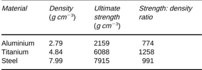
Early rotors were often manufactured of steel or brass, but are now more commonly constructed of aluminium and titanium. Newer carbon composites are also gaining acceptance, with plastics commonly used for small-scale applications and stainless steel for industrial-scale units. Though somewhat more expen-sive, titanium is particularly suitable as it has both a higher strength-to-density ratio and a high resistance to corrosion and erosion. Selected properties for steel, aluminium and titanium are shown inTable 2.
Table 2 Strength data for commonly used rotor construction materials (from Sheeler, 1981)
Material Density Ultimate Strength: density (g cm\3) strength ratio
(g cm\3)
Aluminium 2.79 2159 774 Titanium 4.84 6088 1258
Steel 7.99 7915 991
cellulose nitrate and cellulose acetate, etc. Polycar-bonate is one of the more popular materials owing to its transparency and strength. The choice of material is generally dictated by the properties of the particles to be fractionated and, in high speed separations, by the maximum ratedgforce.
An exhaustive discussion of the many equipment options along with their advantages and disadvan-tages is beyond the scope of this article. Rather, a brief overview is offered of the more common centrifuge designs together with typical applications. Much of the discussion will assume batch operation, though in most cases rotors are available or may be adapted for batch, semi-batch or continuous-mode operation. However, since continuous-mode centri-fuges are so widely used in industrial applications and their analogues are often unavailable in laboratory-scale units, a section describing the more common or innovative continuous-Sow conRgurations is in-cluded.
Bottle Centrifuges
The most common laboratory centrifuge is the bottle centrifuge. Bottle centrifuges consist of a motor-driven vertical spindle to which a horizontal rotor, machined with an even number of sample positions (2}36), is attached. The harness and rotors are covered with a safety shield, which may also serve to reduce air friction and facilitate temperature control. Such units are normally equipped with a timer, tachometer, and manual or automatic braking. Sam-ples may be mixed with the medium prior to loading, or layered on top of a homogeneous medium or density gradient. Bottle centrifuges are usually bench-top units that may operate at speeds up to 30 000 rpm andgmaxof 65 000, but are also available
as larger, free-standing units that generate centrifu-gal forces in excess of 100 000g. Sample capacities range from capillary tube to 1 L bottles (4 L total capacity).
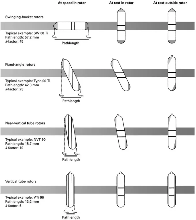
Bottle-centrifuge rotors classiRed as swinging-bucket, Rxed-angle, and vertical (Figure 7). In the
swinging-bucket type, the bottles are in a vertical position at rest but swing outward to a horizontal
orientation as the rotor speed increases. In this ori-entation, the centrifugal force is applied along the length of the tube, making them suitable for rate separations. They may also be used for batch separ-ation of immiscible liquids with some rotors speciR -cally designed to hold separatory funnels to facilitate post-run recovery. However, their high k-factors make them generally unsuitable for differential pelleting, though some rotors constructed to hold short, large-diameter bottles, are designed for such purposes.Fixed-anglerotors are loaded and operated in a similar manner except that, as the name implies, the tube remains at a Rxed angle both at rest and during the run. The Rxed angle is typically 20}453 from the vertical, thoughnear-verticalrotors are less than 103 from the vertical. The Rxed-angle design provides a shorter pathlength (Figure 7) with a corre-sponding reduction in run time (lowerk-factor). Par-ticles that reach the outer wall of the tube during the run aggregate and quickly slide down the tube wall to form a pellet in the bottom. This makes the R xed-angle rotor useful for both pelleting (Figure 3) or isopycnic banding (Figure 4). Verticalrotors can be considered as an extension of Rxed-angle rotors in which the angle of repose is 03from the vertical. In this design, the maximum pathlength is equal to tube diameter, thereby providing the lowestk-factors for a given tube size. Vertical tube rotors are commonly used for isopycnic banding where short run times are important, as compared to near-vertical rotors, which provide short pathlengths yet permit pellet accumula-tion.
The tubes loaded into both vertical andRxed-angle rotors must be sealed during the run to prevent the contents from escaping as the medium moves up the outer wall at speed. O-ring sealing systems or heat sealing are commonly used. If the volume is kept sufRciently low, this step may not be necessary except to prevent the escape of hazardous aerosols, in which case a plastic screw or push-on cap may sufRce.
For pelleting runs, sample recovery entails decant-ing the supernatant from the top and scrappdecant-ing or washing the pellet into a recovery vessel orRlter. For density-gradient runs, the sample may be unloaded from either the top or bottom of the tube with a pump, a Pasteur pipette, syringe, displacement liquid, etc., or by using soft plastic tubes that may be pierced to facilitate recovery of a targeted central band.
Zonal Rotors
Figure 7 Particle separation in swinging-bucket, fixed-angle and vertical-tube rotors. Dark shading represents pelleted material, light shading in floating components, and band are indicated by black lines. (Courtesy of Beckman Instruments, Inc.)
capacity may be insufRcient for certain applica-tions. This obstacle may be addressed with zonal rotors, which provide a larger internal volume for a given radius. Zonal rotors are bowls or cylindrical cavities equipped with a central core and attached vanes or septa that divide the rotor into four or more sector-shaped compartments. Zonal rotors present additional advantages over bottle centrifuges such
can be operated in batch, semi-batch, or continuous modes and may be loaded or unloaded with the rotor stopped (static) or with the rotor spinning ( dy-namic).
Statically loaded and unloaded zonal rotors are also called reorienting gradient rotors. In this method, the gradient is loaded with the rotor at rest then slowly accelerated to permit the gradient to reorient from a horizontal to a vertical conRguration, as illustrated inFigure 8. Solutions of increasing den-sity are loaded to the bottom with the sample solution layered on top after the rotor isRlled. When the rotor is accelerated, the gradient reorientates to a vertical position with the lighter fractions and sample in the centre of the rotor. After centrifugation, the rotor is slowly decelerated and the gradient returns to a hori-zontal orientation. The heavier fractions may be re-movedRrst by displacement with air or the rotor lid removed and the gradient pumped out. Alternatively, the gradient may be displaced with a denser liquid that forces the lighter fractions out Rrst. The ad-vantages of the reorienting gradient technique are simplicity and the avoidance of rotating seals that may leak or fail during dynamic loading/unloading. The major disadvantage is the tendency of the gradi-ent to swirl as it reorigradi-ents, leading to a loss in resolu-tion.
Dynamic loading and unloading, also known as ‘rotating seal’, is conducted as the rotor spins, as illustrated in Figure 9. The gradient is pumped through a rotating seal in the centre of the rotor lid into passages machined into the rotor core, which channel the solutions to the outer wall. The lighter-density solutions are loaded Rrst, forming a vertical layer that is displaced inward by the ensuing denser solutions. An optional high density liquid cushion
may be added last if a reduction in the effective rotor volume is desired. The sample is introduced to the centre of the rotor by reversing the feed/exit lines. The rotor is accelerated to the operating speed for a targeted time, then decelerated to the initial loading speed. In centre unloading, a high density immiscible liquid, such as Fluorinert2+, may be routed to the outer wall, forcing the gradient from the rotor, lighter fractionsRrst. Edge unloading is similar, only a light liquid is pumped to the centre, displacing the heavier fractionsRrst. The gradient may be fractionated as it exits by routing the efSuent through a programm-able fractionator that automatically switches collec-tion vessels, or manually by selecting cutoff points with a density meter, refractometer or UV absorption cell, or by collecting predetermined vol-umes. While somewhat more cumbersome, dynamic loading generally provides better resolution than static loading/unloading.
Ultracentrifuges
‘Ultracentrifuge’ is an ill-deRned term applied to cen-trifuges with rated speeds greater than about 25 000 rpm, regardless of the medium or rotor de-sign. While speed was historically used to designate ultracentrifugation, some manufactures now reserve this term for centrifuges that operate at sufRcient speeds to require a vacuum to reduce frictional drag and/or rotor heating. Most such units are also equipped with refrigerant capability for the same purpose.
Ultracentrifuges are classiRed as preparative or analytical. Preparative ultracentrifuges are used to separate and recover puriRed sample components at speeds ranging up to 150 000 rpm and forces to 900 000g. The rotor conRguration may be any of the types described in this section } bottle, zonal, or continuous}withRxed-angle and vertical-bottle cen-trifuges providing the highest speeds and titanium being the most common material of construction.
Analytical ultracentrifuges, originally developed by Svedberg, are used to study the behaviour of particles during sedimentation. While analytical rotors are available in various shapes and sizes, their deRning feature is a transparent window, typically constructed of quartz or sapphire, that permits the sedimenting particles to be monitored optically during the run. UV absorption and/or refractive index measurements are the most common monitoring techniques. The re-quired sample volume is low, ranging down to 5L, making this a useful technique when sample availabil-ity may otherwise be a limiting factor. Sample recov-ery is generally a secondary consideration, if conduc-ted at all. Analytical ultracentrifuges are available at speeds up to 70 000 rpm and centrifugal forces in excess of 350 000g.
Continuous Centrifuges
Fi
gu
re
8
S
tat
ic
lo
a
d
in
g
a
n
d
u
nl
o
a
d
in
g
o
f
a
z
on
a
l
ro
to
r
w
it
h
a
re
or
ie
n
ti
n
g
g
ra
d
ie
n
t
c
o
re.
(C
o
u
rt
es
y
o
f
B
e
c
k
m
an
In
s
tr
u
me
n
ts
,
In
c
Figure 9 Dynamic loading and unloading of a zonal rotor. (Courtesy of Beckman Instruments, Inc.)
The rotors previously described can be, and often are, adapted for continuous-Sow separations. How-ever, the following discussion focuses on rotors that are designed speciRcally for continuous operation, particularly for industrial applications such as those depicted inFigure 10.
Disc centrifuges Disc centrifuges operate on the principle of differential sedimentation and are used for two-phase (liquid}solid or liquid}liquid) and three-phase (liquid}liquid}solid) separations. These are highly efRcient units with some industrial-scale units generating forces of 10 000gand pelleting of particles as small as 0.1m. Disc centrifuges are essentially a rotating bowl equipped with an internal set of conical settling plates or discs mounted at an angle to the axis of rotation (typically 30}403). The discs serve to decrease the sedimentation pathlength and increase the sedimentation surface area, i.e. capa-city factor. Denser materials sediment onto and slide across the plate surfaces before accumulating on the bowl wall (Figure 11) as the clariRed supernatant
continuously exits. In addition to the parameters of centrifugal force andSow rate, the capacity and per-formance of disc centrifuges are also dependent on the number, spacing and diameter of the plates. Sample mixtures may be introduced to either the interior or outside of the disc stack, depending on the nature and concentration of solids, with most units conRgured for liquid}liquid or liquid}liquid}solid mixtures being centre fed.
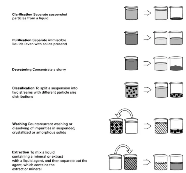
Figure 10 Major industrial applications for continuous centrifuges. (Courtesy of Alfa Laval Separations.)
ports at different radial distances as dictated by the relative concentration of the liquids. Commercial units are available with liquid throughput capacities of 60 m3h\1and holding capacities of 30 L. A
vari-ation on the solids-retaining disc centrifuge is the cylindrical-bowl design shown in Figure 12, which incorporates a series of concentric cylindrical re-tainers for processing liquid}solid mixtures. Unlike the disc centrifuge, in which the feed stream is split and makes a single pass through the disc stack, in the cylindrical-bowl design the liquid stream is routed through each chamber in succession, resulting in a longer residence time, more efRcient recovery, and generally greater capacity (to 70 L). Applications of solids-retaining centrifuges of the stacked-disc or cylindrical-bowl design include separation of cream from milk, organic waste from water, puriRcation of lubricating oils, or removal of water and solids from jet fuel.
Solids-ejecting stacked-disc centrifuges (Figure 11B) are more suitable for processing samples with solids contents to about 15% by volume. These units oper-ate similarly to the solids-retaining design, only solids or sludge that accumulate on the bowl wall are inter-mittently discharged through a hydraulically ac-tivated, peripheral opening. Laboratory models to 18 cm diameter and industrial units to 60 cm are available, with the latter capable of throughputs in excess of 100 m3h\1. Applications for these units
include catalyst recovery, clariRcation of paints and varnishes, treatment of radioactive waste water, and copper extraction.
Figure 11 Disc centrifuge configurations: (A) solids-retaining; (B) intermittent solids-ejecting; and (C) continuous solids-eject-ing. (Courtesy of Alfa Laval Separations.)
Figure 12 Schematic of a cylindrical-bowl centrifuge. (Cour-tesy of Alfa Laval Separations.)
the bowl. Due to the high discharge velocities result-ing from the centrifugal pressures, nozzle erosion can occur. Thus, the materials used for nozzle construc-tion and the ease of replacement of eroded compo-nents should be considered. Newer designs discharge to an internal chamber where the discharge is pumped out as a product stream. Industrial units are available to 200 m3h\1 throughput capacity,
elevated temperature (42003C) or pressure (7 bar) capability, and particle removal to 0.1m.
Applica-tions for continuous-discharge disc centrifuges include production of baker’s yeast, dewatering of kaolin clay, titanium dioxide classiRcation, and coal-tar and tar-sand clariRcation.
Continuous conveyor discharge These centrifuge types integrate an active mechanical solids discharge mechanism in an imperforate bowl for the continuous processing of larger sample volumes. The bowl shape is tubular, having a length-to-diameter ratio of 1.5}5.2, and may operate in either a horizontal or vertical conRguration. The vertical conRguration is generally preferred for reduced or elevated temper-ature and/or pressure applications owing to fewer mechanical problems with seals and heat expansion. The solids-discharge mechanism is most commonly, a helical screw turning at a slightly slower rate than the rotor, though pistons or conveyer belts are also used. Figure 13 illustrates a helical-screw conR g-uration used for three-phase separations (liquid} liquid}solid). Solid}liquid and liquid}liquid conR g-urations with either concurrent or countercurrent Sow regimes are commercially available. Such mech-anical discharge units typically operate at lower cen-trifugal forces (to 5000g) than disc centrifuges. How-ever, they are capable of very high throughput, up to 300 000 L h\1, and can be used to process feed
Figure 13 Schematic of a horizontal continuous-conveyer centrifuge. (Courtesy of Alfa Laval Separations.)
Figure 14 A tubular centrifuge configured for recovery of two liquids and one solids stream. (Courtesy of Alfa Laval Separations.) biotechnology and food sectors for clarifying,
clas-sifying, dewatering and thickening applications.
Tubular centrifuges These centrifuges utilize a ver-tically mounted, imperforate cylindrical-bowl design to process feed streams with a low solids content. Liquid(s) is discharged continuously and solids are manually recovered after the rotor capacity is
reach-ed. One conRguration, designed for recovery of two immiscible liquids and a solid product, is shown in
Figure 14. Other conRgurations for processing solid}liquid or liquid}liquid mixtures are also widely used. Industrial models are available with diameters up to 1.8 m, holding capacities up to 12 kg, through-put rates of 250 m3h\1, and forces ranging up to
Figure 15 Flow regimes in a continuous-flow zonal rotor. (Courtesy of Beckman Instruments, Inc.)
diameters of 4.5 cm, throughput rates of 150 L h\1,
and centrifugal forces ranging up to 62 000g. Because of their high speed and short settling path, tubular centrifuges are well suited for the pelleting of ultraRne particles, liquid clariRcation, and separation of dif-Rcult-to-separate immiscible liquids. In addition to the standard electric motor used for most laboratory centrifuges, laboratory-scale tubular centrifuges are available with turbine drives. Tubular centrifuges were reRned for the separation of penicillin during World War II but since then have largely been re-placed by disc centrifuges because of their limited holding capacity. However, they are still widely used for applications that involve the efRcient recovery of high value products at high purity, especially in the pharmaceutical and chemical industries. Typical applications include recovery ofEscherichia colicells and Su viruses, removal of colloidal carbon and moisture from transformer oils, removal of small par-ticles from lubricating oils, blood fractionation, and de-inking.
Continuous zonal rotors Zonal rotors are often used for smaller scale, semi-batch separations. Opera-tion is similar to that previously described for batch separation only a larger diameter core with a dif-ferent Sow pattern is inserted as illustrated in
Figure 15. Continuous-feed separations in zonal cen-trifuges are best suited for low concentration, high volume samples. Such separations may be conducted with a homogeneous medium for sample pelleting, or with a density gradient for materials that may be adversely affected by pelleting (e.g. viruses that may lose their activity) or if simultaneous isolation of two or more materials is desired. Applications include puriRcation of viruses from tissue-culture media, har-vesting bacteria, or separating Rne clay particles in water pollution studies.
Elutriation rotors Another type of laboratory-scale continuous-Sow centrifugation is elutriation or counterstreaming, used to separate particles with dif-fering sedimentation rates (rate separation). A sche-matic of the elutriation process is shown inFigure 16. Conical or funnel-shaped rotors are used with the small end positioned farthest from the axis of rota-tion. The rotor is initially Rlled with a buffer solution followed by the sample mixture, introduced at a constant rate to the small end of the spinning rotor, where particles experience the opposing forces of the centrifugalReld and theSowing medium. Ini-tially, the frictional force of the carrier medium is greater than the centrifugal force and all particles are swept inward by theSowing carrier. However, as the entrained particles migrate toward the large end of
the chamber, the linear velocity of the carrier de-creases as the cross-sectional area of the rotor in-creases. Due to the greater sedimentation rates for larger particles in a centrifugal force Reld, smaller particles continue to migrate toward the centre of the rotor while larger particles remain suspended or move more slowly, resulting in particle classiRcation. Such separations are semi-batch since, as the concen-tration of larger particles in the rotor increases to capacity, sample feed must be stopped so that these particles may be eluted with a higher velocity rinse solution. Elutriation rotors typically operate at lower centrifugal forces (10 000g) with throughputs to 400 mL min\1. A common application is the
Figure 16 The elutriation process. (Courtesy of Beckman Instruments, Inc.)
Centrifugal Filtration Equipment
In centrifugal Rltration, centrifugal force is used to press a solids suspension against aRlter medium that permits the mother liquor to pass while retaining the solid particles. Such centrifuges are used for the sep-aration of solids from liquid slurries, chieSy in indus-trial applications, and are usually characterized in terms of theRnal moisture content, drainage time and centrifugal force. In addition to the centrifugalReld, the drain or screen area and cake thickness are the primary controllable parameters that govern perfor-mance. Filtration centrifuges are available in numer-ous conRgurations with units often designed or modi-Red for a speciRc application. Three of the more common designs are batch/semi-batch basket centri-fuges, continuous push-type and continuous conical centrifuges.
Basket centrifuges The simplest and most common centrifugal Rltration units are basket centrifuges. They are particularly useful when the nature or con-centration of the solids varies substantially with time or for the recovery of small or difRcult-to-Rlter particles. Basket centrifuges incorporate a perforated cylindrical bowl that is lined with a Rltration me-dium, usually a fabric or metal screen. Industrial units generally spin at relatively low rates ((4000 rpm), are available with bowl diameters ranging from 0.3 m to 2.4 m, and may be operated at elevated temper-atures (3503C) and/or pressures (1 MPa). The slurry is fed to the centre of the basket with the mother liquor passing and the cake accumulating against the Rltration medium. When the accumulated cake vol-ume is sufRcient either to retard further Rltration or unbalance the centrifuge, the solids must be dis-charged. This is achieved in one of three ways: (1) the centrifuge is stopped and the cake is manually scraped, useful for smaller batches when production does not warrant the additional costs of automation,
for processing different materials in a single unit, or when the equipment must be sterilized between batches; (2) the cake is mechanically unloaded at reduced speed by using a single or multiple plow; or (3) the cake is continuously removed at speed with a hydraulicknifein a peeler centrifuge, most useful for moderate production rates and for materials that drain freely. Other basket centrifuges, termed invert-ingTltercentrifuges, haveSexibleRlters that may be inverted to discharge the accumulated solids.
Continuous centrifugal Rlters are more useful for higher volume processing of fast-draining solids in applications that do not require a low level of moisture in the recovered product. They can be further divided into push-type (cylindrical) and conicalRlters.
Push-type centrifugalVlters These units consist of a rotating cylindrical drum that incorporates a feed funnel that rotates with the drum. The slurry is intro-duced via the feed funnel where it is accelerated before being deposited to one end of the drum. Liquids pass through a cylindrical screen under cen-trifugal pressure as the solids accumulate to form a cake. The cake is then pushed by a reciprocating piston toward the exit located at the opposite end of the drum. Push-typeRlters may be single or multiple stage, with the latter incorporating a cylindrical screen with two to six variable-diameter steps. The diagram of a multistage push-typeRlter inFigure 17
illustrates the integration ofRltration and rinse cycles in a continuous operation.