Design of PV Modules Including a Layer between Solar
Cells and Glass Cover to Increase PV Module Lifetime
M. Mokhtar Zayed
Alshorouk AcademyCairo, Egypt
Wagdy R. Anis
Ain Shams UniversityCairo, Egypt
Mohamed Abouelatta
Ain Shams UniversityCairo, Egypt
A. I. Salem
Alshorouk AcademyCairo, Egypt
ABSTRACT
Nowadays, design of the modules of the solar cells (PV modules) makes these cells completely attached to the coat of the glass. Therefore, damaging of the cover glass lead to replace the PV module totally. Furthermore, it is means loss in the solar cells despite being correct and does not damage. This paper proposed solution based on a lamination layer between solar cells and the tempered glass of the PV module to show the feasibility from these PV modules even after the cover glass damaging.
Keywords
Anti-Reflecting Coating Layer (ARC Layer), Photovoltaic modules (PV modules).
1.
INTRODUCTION
This work studies the effect of the lamination layer between solar cells and the tempered glass of the PV module, such a layer enables one to replace only the tempered glass in case of its damage instead of replacing the PV module totally. Thus, the cost of replacement of PV modules at the end of its lifetime is drastically reduced. As a result, a significant reduction in PV systems cost may be achieved.
ZHU, in [1] presents the effects of lamination condition on durability of PV module packaging and performance. Laminating PV modules with EVA using solar ovens is presented in [2] by Richard Komp.
In [3], Kamal Alameh discusses the solar energy harvesting clear glass for building-integrated photovoltaics.
The paper is organized as follows. Section 2 shows the analysis of incident light on solar cell. Section 3 introduces the results of the system. Finally, the paper is concluded in section 4.
2.
ANALYSIS OF INCIDENT LIGHT ON
SOLAR CELL
In this paper, the proposed design is classified into two sections: calculating the reflected power (r) from a silicon solar cell at normal incidence case andin the proposed design case.
Some parameters played an important role in the results of calculating the reflected power (r) such as the refractive index of anti-reflecting coating (nARC), incidence angle from the sun (θinc), refractive index of lamination (nlam) and the incidence wavelength (λair).
2.1
Normal Incidence
The equations used at normal incidence are: Snell's law is depicted in equation (1) [4].
Under normal incidence conditions: θi→0 and θr→0, then
Sin (θi-θr) ≈ tan (θi-θr) ≈ θi-θr (2)
Sin (θi+θr) ≈ tan (θi+θr) ≈ θi+θr (3)
Then from Fresnel's equation the reflected power (r) is given in equation (4).
Combining equation (4) through equations (2, 3) then one finds equation (5).
Note that normal incidence case always measured in case of two axis tracking system.
2.2
The Proposed Design
The proposed design depends on some important factors such as:
a) Incidence angle from the sun (θinc) b) Input wave length from the air (λair) c) Refractive index of lamination (nlam)
d) Refractive index of anti-reflecting coating (nARC)
All these parameters used in Snell's law and substituted in equation (4). So, the reflected power (r) is calculated and the absorption coefficient in silicon solar cell in the two cases of equations (4, 5) can be calculated from equation (6).
αabs in Si = 1 – r (6)
[image:1.595.333.525.583.663.2]The proposed design works under some conditions:
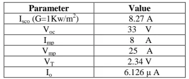
Table 1. Constant parameters in the proposed module
Parameter Value
Isco (G=1Kw/m2) 8.27 A
Voc 33 V
Imp 8 A
Vmp 25 A
VT 2.34 V
Io 6.126 μ A
Finally, all the equations used in the proposed system to get the energy and the power for the designed module are.
2.2.1
Declination angle (δ)
Volume 182 – No. 19, October 2018
[image:2.595.333.522.407.559.2]
The monthly average values of declination angle (δ) and the corresponding average day every month is indicated in table (2).
Table 2. Monthly average declination angles
Month Date Day of
year (d)
Declination angle (δ )
January 17th Jan. 17 -20.9
February 16th Feb. 47 -13.8
Marth 16th Mar. 75 -2.4
April 15th Apr. 105 +9.4
May 15th May 135 +18.8
June 11th June 162 +23.1
July 17th July 198 +21.2
August 16th Aug. 228 +13.5
September 15th Sep. 258 +2.2
October 15th Oct. 288 -9.6
November 14th Nov. 318 -18.9
December 10th Dec. 344 -23.0
2.2.2
Hour angle (ω)
Hour angle is described into equation (8).
2.2.3
Incidence angle (ϴ
T)
Incidence angle is described into equation (9) [13].
Equation (9) is valid for any tilted surface facing the equator.
If such condition (of facing equator) is not fulfilled, then one has to consider the general case considered in the next section.
Let us now consider on interesting special case where the tilt angle (β) is equal to the latitude angle (Φ) under this condition equation (9) becomes equation (10).
The angle of incidence of solar beams on a horizontal surface in a place having latitude (Φ) is given from equation (12).
2.2.4
Sunset Hours (ω
s)
From equation (12), at sunset ϴh = π/2 when ω = ωs yields,
equation (13) [7]-[9].
Now let us determine the sunshine duration on a surface tilted by an angle (β), where equation (9) is applicable.
The sun beams are tangent to the tilted surface when ω = ωs
and ϴT = π/2, using equation (9) yields to equation (14)[8, 9].
In the proposed design the tilt angle (β) equals to the latitude angle (Φ) under this condition (Φ = β) equation (14) becomes
The sunset hour angle on tilted surface (ωs') is always less than or equal to sunset hour angle on horizontal surface thus one can write the following formula represented in equation (15) [7].
Which mean that (ωs') is the minimum value of either (ωs) given by equation (13) and (ωs'') given by equation (14).
2.2.5
Clearness Index (K
T)
Clearness index (KT) which is defined in [10].
(16)
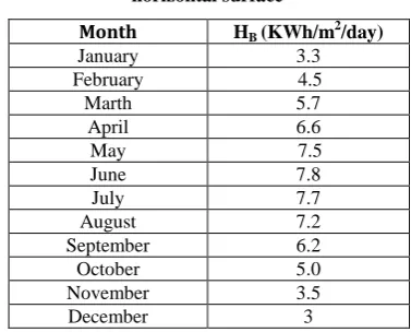
Where (HB) is the global solar radiation on a horizontal surface and its value is given from table (3)[11].
Table 3. Monthly average global solar radiation on horizontal surface
Month HB (KWh/m2/day)
January 3.3
February 4.5
Marth 5.7
April 6.6
May 7.5
June 7.8
July 7.7
August 7.2
September 6.2
October 5.0
November 3.5
December 3
And (Hext) is the monthly average daily extraterrestrial solar insolation (KWh/m2/day) on horizontal surface at the same latitude (Φ) of the site under consideration and can be calculated from equation (17) [10, 11].
7)
Note that the extraterrestrial solar irradiance (KW/m2) on a
surface normal to solar beams is constant and equal to the solar constant (GSC =1.35KW/m2) [12].
n the ro osed desi n the latit de an le ( = 0 north) in Cairo.
2.2.6 The factor (R
b)
that on a horizontal surface (Rb) is described into equation (18).
2.2.7 The global radiation (H
T)
The global radiation (direct plus diffused) on a tilted surface can be obtained from equation (19).
0.5 cos (19)
Where (ρ) is the reflectivity of ro nd (ρ = 0.2 for normal ground and 0.7 for snow).
2.2.8 The instantaneous solar irradiance (G
T)
Equation (20) gives the instantaneous solar irradiance on tilted surface if the solar radiation on horizontal surface (HB) is known; table (3) givesMonthly average global solar radiation on horizontal surface (HB).
2.2.9 The array current (I
A)
From equations (4, 6 and 20) and from the constant parameters of the proposed design from table (1).The current of the array can be calculated from equation (21).
2.2.10 The generated electric power and energy
[image:3.595.357.496.125.315.2]
Fig 1: Equivalent circuit of ideal solar cell
Fig 2: Equivalent circuit of real solar cell
3.
RESULTS FROM MATLAB AND
EXCELL SHEET CALACULATIONS
3.1
Normal Incidence
In this case we discuss the effect of Refractive index of anti-reflecting Coating (nARC) and incidence angle from the sun (ϴinc) on the absorption Coefficient of silicon solar cell (αabs).
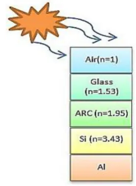
[image:3.595.328.531.360.679.2]Fig 3: Layers of ideal solar cell at normal incidence
Table 4. Relation between the refractive index of antireflecting coating and the absorption coefficient of
silicon solar cell
nARC α abs in Si
1.5 0.847
2 0.931
2.5 0.975
3 0.996
3.5 0.99989797
4 0.994
4.5 0.982
5 0.965
Fig 4: Relation between the refractive index of antireflecting coating and the absorption coefficient of
silicon solar cell
[image:3.595.55.268.469.696.2]Volume 182 – No. 19, October 2018
ϴinc α abs in Si
10 0.924323876
20 0.924303705
30 0.924227208
40 0.924043271
50 0.923718489
60 0.923267873
70 0.922776515
80 0.922386424
[image:4.595.325.534.77.228.2]90 0.922236845
[image:4.595.59.536.245.716.2]Fig 5: Relation between the incidence angles from the sun and the absorption coefficient of silicon solar cell
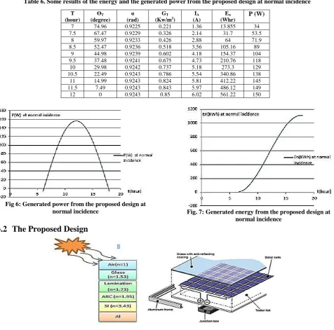
Table 6. Some results of the energy and the generated power from the proposed design at normal incidence
T (hour)
ϴT
(degree)
α (rad)
GT
(Kw/m2) (A)IA (Whr)En P (W)
7 74.96 0.9225 0.221 1.36 13.855 34
7.5 67.47 0.9229 0.326 2.14 31.7 53.5
8 59.97 0.9233 0.426 2.88 64 71.9
8.5 52.47 0.9236 0.518 3.56 105.16 89
9 44.98 0.9239 0.602 4.18 154.37 104
9.5 37.48 0.9241 0.675 4.73 210.76 118
10 29.98 0.9242 0.737 5.18 273.3 129
10.5 22.49 0.9243 0.786 5.54 340.86 138
11 14.99 0.9243 0.824 5.81 412.22 145
11.5 7.49 0.9243 0.843 5.97 486.12 149
12 0 0.9243 0.85 6.02 561.22 150
Fig 6: Generated power from the proposed design at
normal incidence Fig. 7: Generated energy from the proposed design at normal incidence
3.2
The Proposed Design
Table 7. Some results of the generated energy and power from the proposed design at 15th September
T (hour)
ϴT
(degree)
α (rad)
GT
(Kw/m2) (A)IA (Whr)En P (W)
7 74.97 0.9226 0.228 1.42 15.99 35.4
7.5 67.48 0.9229 0.337 2.22 39.78 55.5
8 59.99 0.9233 0.440 2.98 73.32 74.6
8.5 52.51 0.9236 0.536 3.69 115.99 92.3
9 45.02 0.9239 0.622 4.33 167.01 108.3
9.5 37.54 0.9241 0.698 4.89 225.46 122.3
10 30.06 0.9242 0.762 5.37 290.27 134.2
10.5 22.6 0.9243 0.813 5.74 360.27 143.6
11 15.15 0.9243 0.850 6.02 434.21 150.4
11.5 7.82 0.9243 0.872 6.18 510.77 154.6
[image:5.595.144.448.87.228.2] [image:5.595.131.542.245.729.2]12 2.22 0.9243 0.880 6.24 588.58 155.9
Table 8. Some results of the generated energy and power from the proposed module at 16th Marth
T (hour)
ϴT
(degree)
α (rad)
GT
(Kw/m2)
IA
(A)
En
(Whr)
P (W)
7 74.97 0.9226 0.228 1.37 15.35 34.26
7.5 67.48 0.9229 0.327 2.15 38.38 53.82
8 59.99 0.9233 0.428 2.89 70.89 72.35
8.5 52.51 0.9236 0.521 3.58 112.29 89.55
9 45.02 0.9239 0.605 4.20 161.80 105.11
9.5 37.54 0.9241 0.679 4.75 218.54 118.76
10 30.06 0.9242 0.741 5.21 281.45 130.25
10.5 22.6 0.9243 0.790 5.58 349.42 139.4
11 15.15 0.9243 0.826 5.84 421.22 146.05
11.5 7.82 0.9243 0.848 6.00 495.56 150.08
12 2.22 0.9243 0.855 6.06 571.12 151.43
Note that all the results after time (t=12 hour) repeated it self.
Similar as the results before (t=12 hour) in table (6, 7 and 8).
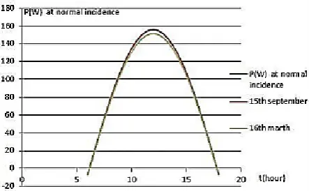
Fig 9: Generated power from the proposed design at normal incidence, 15th Sep and 16th Marth
[image:5.595.56.278.441.578.2]Fig 10: Generated energy from the proposed design at normal incidence, 15th Sep and 16th Marth
[image:5.595.63.270.620.725.2]Fig 11: The monthly average daily generated power in the proposed design
Volume 182 – No. 19, October 2018
4.
CONCLUSION
This paper introduces a full operational and low cost of the proposed system to preserve the solar cells from damage. It is done by placing a layer between the cells and the glass layer. In addition, the damaged glass is replaced only and not eliminates the solar cell completely. In the proposed system, the actual factors affecting on the solar cell are the angle of free fall and refractive index of the Anti-reflecting coating layer but the effect of the proposed layer was simple compared to them.
5.
REFERENCES
[1] [1]ZHU, J., BETTS, T.R.and GOTTSCHALG, R.,
2014,"Effects of Lamination Condition on durability of PV module packaging and performance", proceedings of the 10th photovoltaic science application and technology conference C96 (PVSAT-10), Lough borough university, 23rd _25th April 2014.
[2] [2]Richard Komp, Susan Kinne and Christopher Orr, "Laminating PV Modules with EVA using Solar ovens", American solar energy, 2011.
[3] [3]Kamal Alameh, Mikhail Vasiliev,Ramzy Alghamedi, Mohammad Alam and V.Rosenberg,"Solar Energy Harvesting clear glass for building-integrated photovoltaics",ECU publications 2013.
[4] [4] Rashed, Roshdi (1990)."Apoineer in anaclastics: Ibn Sahl on burning mirrors and lenses".Isis.81 (3):464_491.
[5] [5]P.Cooper, The absorption of solar radiation in solar stills, Solar Energy, Vol.12 (3), (1969).
[6] [6]Renewables 2012:"Global Status Report,"REN21,
2012.
[7] [7]G. N. Tiwari and S. Dubey., "Fundamentals of Photovoltaic Modules and Their Applications", Centre for Energy Studies, Indian Institute of Technology (IIT) Delhi, New Delhi, India,2010.
[8] [8] Saeed Mansour, Prof.Dr Wagdy R.Anis and Prof.Dr Ismail M.Hafez,"Optimum Design of on grid PV system using Tracking System", International Journal of Scientific &Technology, vol.4, pp.50-56, May2015.
[9] [9] Mohamed Nagh, Prof.Dr Wagdy R.Anis and Prof.Dr Ismail M.Hafez,"A proposed solution for partial shadowing",International Journal Of Computer Applications (IJCA),Foundation of Computer science, New York USA, 18 July 2015.
[10] [10] S.klein, Calculation of monthly average insolation on tilted surfaces, Review paper, Solar Energy, vol.19, pp.325-329, (1979).
[11] [11] J.page, he estimation of monthly mean val es of daily total short-wave radiation on vertical and inclined s rfaces from s nshine records for latit des 0 – 0 S, proc.UN Con. On New Sources of Energy, Paper No.35/5/98 (1961).
[12] [12] C. Froehlich, Contemporary measures of the solar constant, The Solar Output and its variations, Colorado Associated University, press, Boulder (1977).
[13] [13] D.Rapp, Solar Energy, Prentice – Hall, Englewood cliffs, NewJersy (1981).