© 2019, IRJET | Impact Factor value: 7.211 | ISO 9001:2008 Certified Journal
| Page 2406
Self-Tuning PID Controller with Genetic Algorithm Based Sliding Mode
MRAS for Induction Motor Drive
M. Ankarao
1, M. Vijaya Kumar
2, J. Sandeep Kumar
31
Asst.Professor, Department of Electrical and Electronics Engineering, JNTUA, Anantapuramu, Andhra Pradesh. India
2Professor, Department of Electrical and Electronics Engineering, JNTUA, Anantapuramu, Andhra Pradesh. India
3
Student, Department of Electrical and Electronics Engineering, JNTUA, Anantapuramu, Andhra Pradesh. India
---***---
Abstract:- Modern industrial processes are becoming moreand more automatized and complex. Therefore, their monitoring and diagnosis systems must be continuously improved. A great majority of today’s industrial applications use induction motors (IMs) to ensure rotational movement, however, usually their speeds are still measured by sensors. A speed observer can be applied in order to decrease the amount of cables and increase reliability by avoiding the use of a measurement device. When an encoder is already present in the industrial process, the sensorless technique can also be used to design a speed sensor fault tolerant drive system.
The speed of IM can be estimated using various techniques and the number of proposed methods is already high. One of the existing solutions, which can be distinguished, is the use of the sliding mode (SM) technique. It is practically always concluded to be the most advantageous in all comparisons. One of the disadvantages is the chattering problem, which arises due to the sign function usage and the necessity to apply a low pass filter. Therefore, many different solutions have been applied to reduce this problem. However, this problem is still not recognized in the case of the SM solutions.
The paper presents a Self Tuned PID with Genetic Algorithm (GA) for sensorless induction motor drives. The
proposed Self Tuned PID with sliding mode
estimationalgorithm is a Model Reference Adaptive System (MRAS) type estimator. Its reference model is the induction motor, while both the stator current and rotor flux estimators create theadaptive system. The estimatoruses asliding mode technique in order to ensurerobustness and simple implementation. The algorithm is based on the equivalent signal technique which allows to significantly decreasing chattering, while simultaneously retaining the properties of the sliding mode estimator. Additionally, the estimator is extended with an auxiliary variable which allows improving the stability of the estimation in regenerating mode operation. The proposed estimator is verified using MATLAB simulation tests.
keywords: induction motor drives, MRAS, online
parameter estimation, rotor flux observer, GA. I. INTRODUCTION
Control of motor is required in both industrial and domestic applications ranging from transportation systems, rolling mills, textile mills in industries to washing machines, fans and pumps in household applications. In such applications motor drives whose speed can be adjusted or varied over a wide range of speeds are of much importance and form an integral part of automation. These types of drives are usually termed as variable speed motor drives or adjustable motor drives. The efficiency of the system or the process can be increased by using these variable speed drives in place of constant speed drives whose speed cannot be adjusted. Hence, these variable speed drives are mostly employed in industrial applications[1].
2 Estimation of Speed
It is desirable to avoid the use of speed sensors from the standpoints of cost, size of the drive, noise immunity and reliability. So the development of shaft sensorless adjustable speed drive has become an important research topic. Many speed estimation algorithms and sensorless control schemes [22] have been developed during the past few years. The speed information required in the proposed control technique is estimated by the algorithm described in this section. The speed of the motor is estimated by estimating the synchronous speed and subtracting the command slip speed. The synchronous speed is estimated using the stator flux components, because of its higher accuracy compared to estimation based on rotor flux components.
The rotor speed of an induction motor is expressed in terms of synchronous and slip (angular) frequencies is as follows:
ωr= (ωe– ωsl)/P (1)
© 2019, IRJET | Impact Factor value: 7.211 | ISO 9001:2008 Certified Journal
| Page 2407
scheme, the synchronous frequency is estimated and slipfrequency is assumed as command. So the estimated rotor speed of the sensorless drive is obtained from the above equation as: Where,
The estimated synchronous frequency is derived based on the rotor flux model, or the stator flux model. The principles of both the methods are briefly explained bellow.
(2)
If ψβr and ψαr are the two components of the rotor flux vector in the stationary (α-β)reference frame as shown in Fig. 2.1 (a), the electrical angle of the rotor flux vector is defined as:
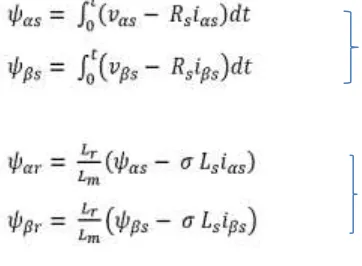
From the basic equation of induction motor in stationary (α-β) reference frame, the stator and rotor flux linkages are given by
equation (3) and equation.(4)
Equation(3) shows that the stator flux depends on the stator resistance and measured stator voltages and currents. Equation (4) shows that the rotor flux depends on the estimated stator flux and requires the knowledge of the inductances of the machine, especially the stator leakage inductance (σ Ls). Usually the stator resistance can be measured fairly accurately. Hence stator flux can be estimated more accurately compared to the rotor flux. Therefore the estimated stator flux can be used to derive the synchronous frequency.
[image:2.612.344.567.67.243.2]The block diagram of the described speed estimation algorithm with the sensorless speed control scheme is shown in fig 2.1
Fig 2.1 Induction motor drive system with sensorless speed control scheme
3. MRAS SYSTEM
In this section a brief survey of different control techniques for induction motor drive is presented. As in this research the main focus is on the control of induction motor using model reference adaptive system (MRAS), the different types of MRAS schemes and their draw backs are also analyzed. In the above discussed estimation schemes either open loop or closed loop speed and flux linkage estimators were utilized. It was also discussed that the accuracy of the closed loop estimators is better than the open loop estimators. In this section a closed loop speed estimation scheme using the Model Reference Adaptive System (MRAS) is described.
[image:2.612.37.218.355.488.2]© 2019, IRJET | Impact Factor value: 7.211 | ISO 9001:2008 Certified Journal
| Page 2408
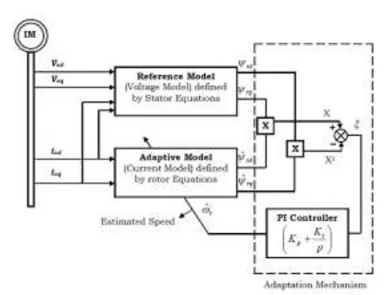
Fig. 2.2 Block diagram of speed estimation using MRASThe above equations do not contain rotor speed andtherefore does not get affected by rotor speed and hence it is taken asreference model. These equations can be written in matrix format as
(5)
The current model consisting of rotor is obtained and is given in equations
(6)
The current model given in equations (6) consists of rotor speed and hence gets affected by it. Therefore this model is known as adaptive model or adjustable model. The reference model and the adaptive model are used to estimate the rotor flux linkages. The angular difference of the outputs of the two estimators known as error
is given as in equation
(7)
This is used as speed tuning signal that is given as input to adaptation mechanism, which forms the main part of the MRAS scheme. The adaptation mechanism conventionally utilizes a PI controller. When the error between the two models is not zero then the adaptation mechanism tunes the rotor speed. In other words when the error between the rotor flux linkages (X – X1) is not zero, the PI controller tunes the rotor speed. The rotor speed identification algorithm is actuated byte error signal generated when the error is not zero, making the error converge to zero. The estimated speed by using MRAS scheme is given as
where K p and Ki are proportional and integral gain constantsrespectively.
4. Sliding Mode Observer
SMO with observer feedback in the form of sign of the stator current estimation error. To identify Speed, Various adaptation mechanism can be used such as Integration of vector product of the rotor flux and sign of the stator current for attaining low frequency signal(LFS) from sign function. Which is value of vector product of the rotor flux and the stator current error. SMO’s with open loop equation to estimate the speed based on back emf value (or) slip speed expression. Which are strongly dependent on the motor parameters and based on derivative of the rotor flux vector components.
5. Genetic algorithms
© 2019, IRJET | Impact Factor value: 7.211 | ISO 9001:2008 Certified Journal
| Page 2409
population. Each member in this population is evaluatedand assigned a fitness value. In the selection procedure, some selection criterion is to select a certain number of strings, namely parents, from this population according to
their fitness values. Strings with higher fitness values have
more opportunities to be selected for reproduction in next step. Next, in crossover procedure, selected strings from old population are randomly paired to mate. For binary coding, a cross-site is determined according to some law, and the paired strings exchange all characters following the cross-site. Crossover usually results in two new strings, namely, two children that are expected to combine the best characters of their parents. Mutation simply changes one bit 0 to 1 and vice versa, at a position determined by some rules. Mutation is simple but still important in evolution because it increases the diversity of the population members and enables the optimization to get out of local optima. After mutation, a new generation is created, and thus becomes the parents for next generation. This process is iterated until convergence is achieved or a near optimal. Gas operates on a population (a number of potential solutions). The population at time t is represented by the time-dependent variable P (t), with the initial population of random estimates being P (0).
Begin t=0
Initialize P (t)
Evaluate P(t) (fitness) while not finished do begin
t=t+1
select P(t) from P(t-1) alter (cross and mutation) P(t)
evaluate P(t) (fitness) end
en begin t=0
initialize P(t)
evaluate P(t) (fitness) while not finished do begin
t=t+1
select P(t) from P(t-1) alter (cross and mutation) P(t)
evaluate P(t) (fitness) end
en begin t=0
initialize P(t)
evaluate P(t) (fitness) while not finished do begin
t=t+1
select P(t) from P(t-1) alter (cross and mutation) P(t)
evaluate P(t) (fitness) end
en begin t=0
initialize P(t)
evaluate P(t) (fitness) while not finished do begin
t=t+1
select P(t) from P(t-1) alter (cross and mutation) P(t)
evaluate P(t) (fitness) end
en begin t=0
initialize P(t)
evaluate P(t) (fitness) while not finished do begin
t=t+1
select P(t) from P(t-1) alter (cross and mutation) P(t)
evaluate P(t) (fitness) end
en begin t=0
initialize P(t)
evaluate P(t) (fitness) while not finished do begin
t=t+1
select P(t) from P(t-1) alter (cross and mutation) P(t)
evaluate P(t) (fitness) end
© 2019, IRJET | Impact Factor value: 7.211 | ISO 9001:2008 Certified Journal
| Page 2410
6. SIMULATION AND RESULTS:1. Performance of the proposed EqSM-MRAS estimator with auxiliary variable in the case of rapid speed reversal for Real and estimated Speed
2. Performance of the proposed EqSM-MRAS estimator with auxiliary variable in the case of rapid speed reversal for high frequency signal and its filtered form
3.Performance of the proposed EqSM-MRAS estimator with auxiliary variable in the case of rapid speed reversal for auxiliary variable, estimated and filtered
4. Performance of the proposed EqSM-MRAS estimator with auxiliary variable in the case of rapid speed reversal for Estimated and real amplitudes of rotor flux
© 2019, IRJET | Impact Factor value: 7.211 | ISO 9001:2008 Certified Journal
| Page 2411
6. Performance of the proposed EqSM-MRAS estimatorwith auxiliary variable in the case of rapid speed reversal forstator current vector components estimation errors
7. Estimation of stability in regenerating mode
8. Estimation of stability in regenerating mode with auxilary variable
9. Estimation of stability in regenerating mode without auxilary variable
10. Estimated flux in rotor parameters variation
© 2019, IRJET | Impact Factor value: 7.211 | ISO 9001:2008 Certified Journal
| Page 2412
Fig.12 Characteristic curves of Torque wrt time usingPI and PID controller with GA
Fig.13 Estimated speed With filter
fig.14 Estimated speed without filter
V, CONCLUSION
This paper proposed a parameter estimation scheme for IFOC of IMs. In this scheme, the errors in the phase and in the magnitude of the current model rotor flux, from that given by the designed observers, are input to the adaptive mechanisms respectively to estimate both the rotor resistance and the mutual high-order TSMO providing the state variable, the back-EMF, and a first-order sliding mode
observer estimating the rotor flux Itself. As demonstrated by simulation, the rotor flux coming out of the observers is highly robust to the mismatch of the rotor resistance and/or of the mutual inductance, which allows it to be used as a reference in the ANFIS MRAS-based estimations of these two parameters: the rotor resistance and the mutual inductance. Although there is coupling between the estimation of the resistance and that of the inductance, their actual values can still be obtained robustly over time. If a decoupling method can be found and integrated into the parameter estimation scheme in future investigation, the converging process would be expedited and the estimating performance would be improved further.
REFERENCES
[1] R. Krishnan, and A. S. Bharadwaj, “A review of parameter sensitivity and adaptation in indirect vector controlled induction motor drive systems,” IEEE Trans. Power Electron., vol.6, no.4, pp.695-703, Oct. 1991.
[2] F. Jadot, F. Malrait, J. M. Valenzuela, and R. Sepulchre, “Adaptive regulation of vector-controlled induction motors,” IEEE Trans. Control Syst. Technol., vol.17, no.3, pp.646-657, May 2009.
[3] S. Sul, “Control of electric machine drive systems,” John Wiley & Sons, Inc., New Jersy: Hoboken, pp.236-245, 2011.
[5] S. M. N. Hasan, and I. Husain, “A Luenberger-sliding mode observer for online parameter estimation and adaptation in high-performance induction motor drives,” IEEE Trans. Ind. Appl., vol.45, no.2, pp.772-781, Mar./Apr. 2009.
[6] H. A. Toliyat, E. Levi, and M. Raina, “A review of RFO induction motor parameter estimation techniques,” IEEE Trans. Energy Convers., vol.18, no.2, pp. 271-283, June 2003.
[7] X. Zhang, “Sensorless induction motor drive using indirect vector controller and sliding-motor observer for electric vehicles,” IEEE Trans. Veh. Technol., vol. 62, no.7, pp.3010-3018, Sept. 2013.
[8] J. Kan, K. Zhang, Z. Wang, “Indirect vector control with simplified rotor resistance adaption for induction machines,” IET Power Electron., vol.8, iss.7, pp.1284-1294, 2015.
[9] C. Attainanese, G. Tomasso, A. Damiano, I. Marogiu, A. Perfetto, “A novel approach to speed and parameters estimation in induction motor drives,” IEEE Trans. Energy Convers., vol.14, no.4, pp.939-945, Dec. 1999.
© 2019, IRJET | Impact Factor value: 7.211 | ISO 9001:2008 Certified Journal
| Page 2413
measurements,” IEEE Trans. Energy Convers., vol.17, no.1,pp.55-60, Mar. 2002.
[11] S. K. Sul, “A novel technique of rotor resistance estimation considering variation of mutual inductance,” IEEE Trans. Ind. Appl., vol.25, no.4, pp.578-587, Jul./Aug. 1989.
[12] E. Levi, M. Kola, and S. N. Vukosavic, “A method for mutual curve identification in rotor flux oriented induction machines,” IEEE Trans. Energy Convers., vol. 15, no. 2, pp. 157–162, Jun. 2000.
[13] M. S. Zaky, M. M. Khater, S. S. Shokralla, and H. A. Yasin, “Wide-speed-range estimation with online parameter identification schemes of sensorless induction motor drives,” IEEE Trans. Ind. Electron., vol. 56, no. 5, pp. 1699–1707, May. 2009.
[14] A. Dittrich, “Parameter sensitivity of procedures for on-line adaptation of the rotor time constant of induction machines with field oriented control,” IEE Proc.-Electr. Power Appl., vol.141, no.6, pp. 353-359, Nov.1994.
[15] J. C. Moreira, and T. A. Lipo, “A new method for rotor time constant tuning in indirect field oriented control,” IEEE Trans. on Power Electron., vol. 8, no. 4, pp. 626–631, Oct. 1993.
[16] S. Wade, M. W. Dunnigan, and B. W. Williams, “A new method of rotor resistance estimation for vector-controlled induction machines,” IEEE Trans. Ind. Electron., vol. 44, no. 2, pp. 247–257, Apr. 1997.
[17] M. W. Degner, J. M. Guerrero, and F. Briz, “Slip-gain
estimation in field-orientation-controlled induction
machines using the system transient response,” IEEE Trans. Ind. Appl., vol. 42, no. 3, pp. 702-711, May./June. 2006.
[18] H. A. Toliyat, M. S. Arefeen, K. M. Rahman, and D. Figoli, “Rotor time constant updating scheme for a rotor flux-oriented induction motor drive,” IEEE Trans. on Power Electron., vol. 14, no. 5, pp. 850–857, Sep. 1999.
[19] T. Orlowska-Kowalska, “Application of extended Luenberger observer for flux and rotor time-constant estimation in induction motor drives,” IEE Proc. Part D, vol.136, no.6, pp.324-330, Nov. 1989.
[20] J. Laowanitwattana, and S. Uatrongjit, “Estimation of induction motor states and parameters based on extended kalman filter considering parameter constraints,” in Proc. of SPEEDAM, Capri, Italy, Jul. 28, 2016, pp.755-760.
[21] A. B. Proca, and A. Keyhani, “Sliding-mode flux observer with online rotor parameter estimation for induction motors,” IEEE Trans. Ind. Electron., vol.54, no.2, pp.716- 723, April. 2007.
[22] S. N. Vukosavic, and M. R. Stojic, “On-line tuning of the rotor timeconstant for vector-controlled induction motor in position control applications,” IEEE Trans. Ind. Electron., vol. 40, no. 1, pp. 130–138,Feb. 1993.
[23] J. Kan, K. Zhang, Z. Wang, “Indirect vector control with simplified rotor resistance adaptation for induction machines,” IET Power Electron., vol.8, iss.7, pp.1284-1294, 2015.
[24] A. N. Smith, S. M. Gadoue, and J. W. Finch, “Improved rotor flux estimation at low speeds for torque MRAS-based sensorless induction motor drives,” IEEE Trans. Energy Convers., vol.31, no.1, pp. 270-282, Mar. 2016.
[25] I. Benlaloui, S. Drid, L. C. Alaoui, and M. Ouriagli, “Implementation of a new MRAS speed sensorless vector control of induction machine,” IEEE Trans. Energy Convers., vol.30, no.2, pp.588-595, Jun. 2015.
[26] R. D. Lorenz, and D. B. Lawson, “A simplified approach to continuous online tuning of field oriented induction machine drives,” IEEE Trans. Ind. Appl., vol. 26, no. 3, pp. 420–424, May./Jun. 1990.