Catalysts for Molecular Photoelectrochemical Hydrogen
Evolution
By
Rebecca Lynn McCoy
Submitted to the Department of Chemistry as supplement to the requirements for the degree of
Bachelor of Science in Chemistry with Honors
at the
University of North Carolina at Chapel Hill
_______________________________________ Faculty Advisor
Abstract
Production of hydrogen from light-driven water splitting, photoelectrochemical hydrogen evolution for example, is an attractive method to store solar energy. Typically,
photoelectrocatalytic systems require an expensive high purity semiconductor light absorber (e.g. silicon) and a precious metal heterogeneous catalyst (e.g. platinum). The Miller group recently reported a semiconductor-free approach to photoelectrochemical hydrogen evolution with a single homogeneous photoelectrocatalyst, [Cp*Ir(2,2’-bipyridine)(H)]+
(Cp* =
pentamethylcyclopendienyl). To better understand this approach to hydrogen production, a series of structural analogues have been prepared and analyzed. Ligand alteration changes the
characteristics of the catalyst and understanding the influence of different ligands will guide future catalyst design. Complexes containing pyridine, di(2-pyridyl)ketone, and various alpha-diimine ligands have been synthesized and studied using electrochemical techniques such as cyclic voltammetry and chronoamperometry under irradiation. A new catalyst,
Contents
1 Introduction
2 Results
2.1Synthesis and Characterization of [Cp*Ir(Cl)(dpk)]Cl
2.2Synthesis and Characterization of [Cp*Ir(Cl)(p-tolyl BIAN)]Cl 2.3Synthesis and Characterization of [Cp*Ir(Cl)(pm-DAB)]Cl 2.4Synthesis and Characterization of [Cp*Ir(Cl)(pyridine)2]OTf 2.5Synthesis and Characterization of [Cp*Ir(Cl)(nicotinic acid)2]OTf
2.6Synthesis and Characterization of [Cp*Ir(Cl)(trifluoromethyl pyridine)2]OTf 2.7Synthesis of [Cp*Ir(Cl)(cyanopyridine)2]OTf
3 Discussion
3.1Synthesis of Iridium chloride complexes 3.2Hydride Formation
3.3Photochemical Activity
4 Conclusion
5 Future Work
A Appendix A - Electrochemistry
B Appendix B - Synthesis
1.
Introduction
This research investigates how to store energy from visible light in chemical bonds by using hydrogen evolving molecular photoelectrocatalysts. The modern energy economy is based on burning fossil fuels, which produce carbon dioxide, a greenhouse gas accumulating in Earth’s atmosphere.1 With the growing demand for energy and diminishing fossil fuel sources, clean pathways for producing energy are being explored. The sun, which irradiates the Earth with more energy in one hour (4.3•1020 J) than the whole world consumes in a year (4.25•1020 J), has inspired research into capturing and storing sunlight to meet energy demands.2
Unlike commercial photovoltaics which produce electricity directly, production of hydrogen has been proposed as a way to store solar energy. Light energy can be stored by splitting water into hydrogen and oxygen. The idea is simple: break the bonds in water and form a new, higher energy bond between two hydrogens. Subsequent combustion of hydrogen
produces water: it does not form any carbon dioxide.
One method for hydrogen evolution is photoelectrochemical water-splitting. Typically, photoelectrocatalytic systems require a light absorber like a semiconductor (e.g. silicon) and a hydrogen producing catalyst (e.g. platinum). When a photon is absorbed by the semiconductor, an electron is promoted to the conduction band. The electron is then transferred to the platinum which catalyzes the formation of the H-H bond.3
Recent research from the Miller Group has developed a single homogeneous complex that both absorbs light to form hydrogen and is regenerated by electrons.4 The molecular
2,2’-bipyridine), as shown in the catalytic cycle in Figure 1. [Cp*Ir(bpy)(Cl)]Cl
undergoes a two electron reduction and, in neutral water, is protonated to become [Cp*Ir(bpy)(H)]+ . When the complex is irradiated at 460 nm, H2 is released, regenerating the catalyst. Because the photoelectrochemical production of H2 by a single homogeneous complex is a novel approach, interest has turned to exploring the limits of this system by changing the structure of the complex. Analyzing different ligands changes the chemical structure and
electronics of the complex. Through comparison to [Cp*Ir(bpy)(Cl)]+, the ligand features that are important for molecular photoelectrochemical hydrogen evolution can be determined.
New molecular photoelectrocatalysts were synthesized and analyzed by using different ligands in place of bpy. [Cp*Ir(bpy)(H)]+ and closely related complexes combine photochemical and electrochemical process into a single catalytic cycle, but greater activity at lower applied potentials is sought. Modifications to bpy can move the reduction to lower potentials, but the complex can simultaneously become more acidic and less stable.
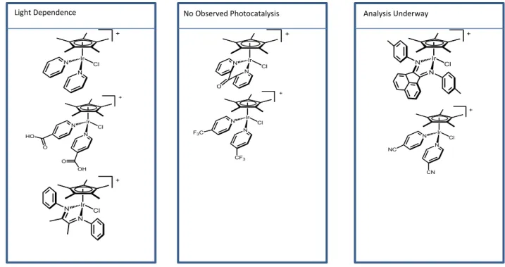
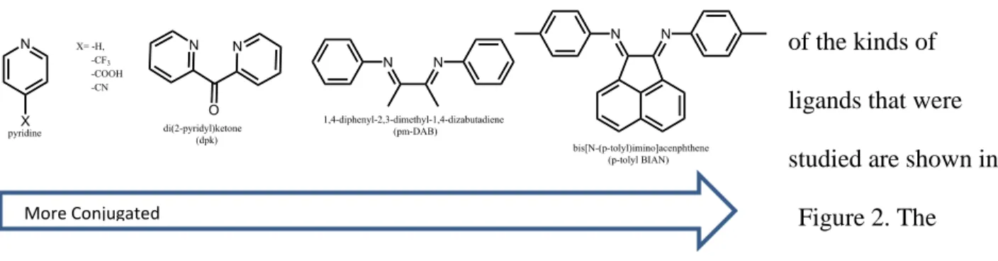
A few examples of the kinds of ligands that were studied are shown in
Figure 2. The ligands of Figure 2 each possess desired features to help for the determination of the structural requirements for molecular photoelectrochemical hydrogen evolution
The alpha-diimine ligands were chosen because the conjugation is different between the nitrogen rings from the bpy. Alpha-diimine ligands have been known to catalyze hydrogen transfer to ketones in ruthenium complexes5 and to help form stereospecific polymerizations in palladium complexes.6 Half-sandwich iridium complexes with these ligands formed novel compelxes. The two alpha-diimine ligands chosen were
1,4-diphenyl-2,3-dimethyl-1,4-dizabutadiene (pm-DAB) and bis[N-(p-tolyl)imino]acenaphthene (p-tolyl BIAN) to determine if the hydrogen evolving catalytic cycle can occur without the nitrogen being part of an aromatic ring.
The pyridine ring was used to make a bis-pyridine product. [Cp*Ir(pyridine)2(Cl)]+
determined if the two rings require a connection between them to produce the desired results and to form a stable complex. To study the effects of electron withdrawing groups on the reduction potential, were added to the para position of the pyridine.
Di(2-pyridyl)ketone (dpk), has similar features to pyridine, but with some conjugation between the pyridine rings. Dpk has been used on palladium catalyst to help in alkene
activation.7 The dpk ligand helped with the determination of if the connection between the rings
Figure 2. The ligands that were used for analysis of the molecular photoelectrochemical hydrogen evolution are shown above.
is important for the observed reactivity. The connection between the rings might help defer ligand loss during photochemical processes. The goal was to study each of these ligands on the iridium catalyst to find a stable alternative for molecular photoelectrochemical hydrogen evolution.
2.
Results
2.1
Synthesis and Characterization of [Cp
*Ir(Cl)(dpk)]Cl
[Cp*Ir(Cl)(di-pyridyl ketone)]Cl (1) was prepared from [Cp*Ir(Cl)2]2 and di(pyridyl) ketone following a modification of the synthesis of [Cp*Ir(Cl)(bpy)]Cl.8 The complex was determined to be pure by 1H NMR.
The dpk ligand has been observed to attach to the iridium catalyst at the oxygen as well as the nitrogen (Figure 3),9 which could affect the formation of the hydride. The NMR [1H
NMR(CD3CN): δ 8.94 (d, 2H), 8.23 (m, 4H), 7.88 (ddd, 2H), 1.32 (s, 15H)] shows that complex with the nitrogen bonding if formed with comparison to literature values on rhodium.9
In order to determine the potentials that electron transfer occurs, cyclic voltammetry was used. In a Cyclic Voltammogram (CV), the potential is changed at variable rates and the current
passing through the electrodes is measured. [Cp*Ir(bpy)(Cl)]Cl has two reduction potentials, one for the two electron transfer to form the hydride [Cp*Ir(bpy)(H)]+ and a more negative one electron transfer for the Ir-HIII /Ir-HII reduction. This suggests the two electron process forms Cp*Ir(bpy) and is followed by rapid pronotation. The reaction is shown in Figure 4 for [Cp*Ir(bpy)(Cl)]+.
Figure 3.In the DPK ligand, the oxygen is known to coordinate to the metal center.
CVs in 0.1 M pH 7 phosphate buffer of [Cp*Ir(Cl)(dpk)]Cl showed three irreversible reduction features at – 0.62 V,–
0.72 V and at – 1.2 V referenced to an Ag/AgCl electrode as shown in Figure 5. During the course of the experiment, the first peak decreased in current while the second peak grew as the solution changed from yellow to clear.
[Cp*Ir(dpk)(Cl)]+ decomposed in water over time accounting for the color change in the solution which is due to loss of the ligand.
To analyze photochemical H2 formation, chronoamperometry (CA) was used with the added variable of light produced either by a 460 nm LED lamp or a broad spectrum white tungsten halogen lamp. Chronoamperometry tracks the change in current over time at a fixed potential; we changed the variable of light to see if photochemistry was involved. The CA measurement taken at -0.8 V showed that the complex was not active under these conditions. A 1H NMR spectrum showed that [Cp*Ir(dpk)(Cl)]+ was not stable in methanol, with six peaks compared to the three expected in the aromatic region indicating that two different complexes were being present. Mass spectrometry analysis was completed to determine that in one of the products a methoxy group was replacing the chloride to form [Cp*Ir(OCH3)(dpk)]Cl. Electrochemical studies of [Cp*Ir(dpk)(Cl)]+ completed in a acetonitrile solution did not pass a higher current when exposed to light, but irreversible reduction peaks were observed at -1.01 V and -1.85 V referenced to Ag/AgCl.
Figure 6. CV of [Cp*Ir(Cl)(dpk)]Cl (1) in 0.1 M pH 7 phosphate buffer
2.2
Synthesis and Characterization of [Cp*Ir(Cl)(p-tolyl BIAN)]Cl
Using an analogous method used for (1), [Cp*Ir(Cl)(p-tolyl BIAN)]Cl (3) was formed. The complex was deteremined to be pure by 1H NMR.
Electrochemical analysis was completed in 0.1 M pH 7 phosphate buffer which revealed a peak at -0.32 V was believed to be the hydride oxidation peak. As 1 M H3PO4 was added, the oxidation decreased to the extent seen in Figure 6, but did not disappear even under very acidic conditions (pH 1.15). This oxidation peak could be due to some silver being in present in the solution. The disappearance of the more negative potential at -0.61 V could be the IrI/III
transition. There was no light dependence observed with 460 nm LED lamp in these conditions.
2.3
Synthesis and Characterization of [Cp*Ir(Cl)(pm-DAB)]Cl
Using an analogous method for (1), [Cp*Ir(Cl)(pm-DAB)]Cl (2) was formed.
Electrochemical analysis was started in 0.1 M pH 7 phosphate buffer. A reversible reduction peak was observed at -0.44 V. 1 M H3PO4 was added to the solution and the oxidation peak decreased in current. The current increased
Figure 6. The CVs for [Cp*Ir(Cl)( p-tolyl BIAN)]Cl in 0.1 M pH 7 phosphate buffer with the addition of 1M H3PO4.
250mV/s, no acid 250 mV/s, acid
Figure 7. The CVs for [Cp*Ir(Cl)( pm-DAB)]Cl in 0.1 M pH 7 phosphate buffer with the addition of 1M H3PO4.
10 mV/sec Dark
when exposed to white light as CVs were taken at slow scan rates suggesting a slow electron transfer reaction was occurring. This increase in current is shown in Figure 7.
Bulk electrolysis, which holds the electrode at one potential for an extended time, was used to isolate the product of the reduction in hopes of forming a hydride. Bulk electrolysis at -0.6 V in 1 M HCl was completed in the dark to form the hydride. During this experiment, the complex decomposed into an opaque white solid and a yellow solution suggesting that the complex was not stable under these conditions.
2.4
Synthesis and Characterization of [Cp*Ir(Cl)(py)
2]OTf
Figure 7The synthesis of [Cp*Ir(Cl)(py)2]OTf (4) was carried out using a procedure that was by analogous to that used for the
preparation of (1). The 1H NMR exhibited a 8:30 ratio of aromatic pyridine protons to Cp* protons. From literature, the ratio suggested the
[Cp*Ir(Cl)2(pyridine)]+ was formed. The addition of silver triflate to the synthesis formed the desired
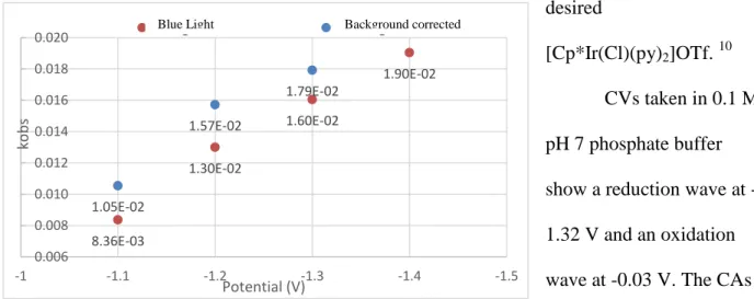
[Cp*Ir(Cl)(py)2]OTf. 10 CVs taken in 0.1 M pH 7 phosphate buffer show a reduction wave at -1.32 V and an oxidation wave at -0.03 V. The CAs
8.36E-03 1.30E-02 1.60E-02 1.90E-02 1.05E-02 1.57E-02 1.79E-02 0.006 0.008 0.010 0.012 0.014 0.016 0.018 0.020 -1.5 -1.4 -1.3 -1.2 -1.1 -1 ko b s Potential (V)
Background Corrected Blue Light
Figure 9. Rate of catalysis for [Cp*Ir(Cl)(py)]2OTf with blue light
Background corrected Blue Light
showed increase in current under irradiation at -1.65 V with the blue lamp and white lamp. The rate of catalysis with blue light was calculated to be 0.014 s-1, which is half the rate for
[Cp*Ir(bpy)(Cl)]+ hydrogen evolution. The rate was calculated by taking CAs of 0.1 M pH 7 phosphate buffer solution with [Cp*Ir(Cl)(py)2]OTf in both the dark and with blue light exposure at different potentials. The rates were background corrected by subtracting out the CAs taken at the same potentials in 0.1 pH 7 phosphate buffer solutions without any complex present in the solution.
Electrolysis at -1.55 V protected from light for 90 min produces a red-orange solution from a light yellow starting material. Three peaks were observed in the hydride region of the 1H NMR, -9.94 ppm, -12.87 ppm, and -15.54 ppm meaning that three different hydride complexes were formed. It is likely that one or both of the ligands could have been removed from the complex which would give the other hydrides. When the NMR tube was photolysized, the peak at -9.94 ppm decreased while the two other hydride peaks remained a constant intensity. In [Cp*Ir(bipyridine)(Cl)]+, the hydride forms the chloride complex and hydrogen gas when exposed to blue light. Figure 9
To better understand the product of bulk electrolysis, chemical synthesis of
[Cp*Ir(py)2(H)]+ was attempted. [Cp*Ir(Cl)(py)2]OTf (10 mg, 0.013 mmol) was stirred in 3 mL 3 M pH 5 NaO2CH under inert atmosphere. After one hour, the vial was vented to release the pressure formed by carbon dioxide. The solution went from an orange-red to a light yellow over the course of the experiment. The solution was filtered and washed three times with three milliliters of
dichloromethane. The dichloromethane fraction was pumped down and 1H NMR was taken. One peak was observed in the hydride region at -12.76 ppm. A second attempt at forming the hydride used sodium borohydride in methanol. The solution immediately turned red then to green over time. The solution was pumped down. 1H NMR was taken to reveal three different hydride peaks at -9.90, -13.36 and -13.56 ppm.
Since the [Cp*Ir(Cl) (py)2]OTf had a much more negative potential than was desired, more complexes with this general structure were analyzed. Electron withdrawing groups (CN, -CF3, and –COOH) were placed in the para-position of the pyridine in hopes of shifting the reduction to a more positive potential.
2.5
Synthesis and Characterization of [Cp*Ir(Cl)(nicotinic acid)
2]OTf
[Cp*Ir(Cl)(nicotinic acid)2]OTf (6) was formed with the same synthesis of (4). Despite the presence of 24% free ligand, preliminary photoelectrocatalytic screening was performed to test the viability of the catalyst. Though two irreversible reduction features were observed at -1.32 V and -1.49 V, no light dependence was observed. An oxidation peak was observed at 0.10 V. The CAs were inconclusive about light dependence due to the negative reduction potential being on the edge of the potential window in water. The catalytic rate without background correction was calculated to be 0.010 s-1, which is lower than it would be with background correction.
2.6
Synthesis and Characterization of [Cp*Ir(Cl)(trifluoromethyl pyridine)
2]OTf
was completed in pH 7 phosphate buffer. A poorly resolved reduction peak was observed at 1.45 V and an oxidation peak at 0.22 V. The CAs displayed 460 nm LED light dependence at -1.40 V. Further studies need to be completed to determine the photochemical reaction.
2.7
Synthesis of [Cp*Ir(Cl)(cyanopyridine)
2]OTf
3.
Discussion
3.1
Synthesis of Iridium Complexes
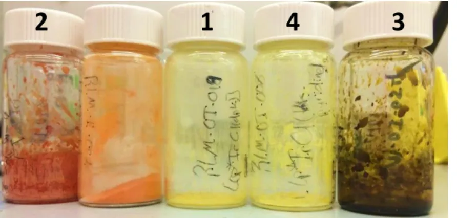
The iridium complexes shown in Figure 11were synthesized and purified using methods in analogy to the literature. For all of the complexes, the main impurities were the starting materials, both free ligands and the unreacted [Cp*Ir(Cl)2]2. Through a process of recrystallization complexes, it was possible to obtain high purity samples of (1), (2), and
(4) became clean. Attempts to purify (3),(5), (6), and (7) are still underway.
The complexes were colorful as can be seen in Figure 12. The color observed is the complimentary to the wavelength of light that is absorbed. The UV/Vis for these
complexes are shown in Figures 13-14.
A table comparing the wavelength of maximum absorbance is in Table 1. The reduction and oxidation potentials are also recorded.
max
(nm) Reduction Potential (V) Oxidative Potential (V)
[Cp*Ir(DPK)Cl] (1) 327 -0.62, -0.72, and -1.2
[Cp*Ir(pm-DAB)Cl] (2) 390 -0.44
[Cp*Ir(p-tolyl BIAN)Cl] (3) 362 -0.32
[Cp*Ir(py)2Cl] (4) 297 -1.32 -0.03
[Cp*Ir(trifluoromethyl pyridine)2Cl] (5) 302 -1.45 0.22
[Cp*Ir(nicotinic acid)2Cl] (6) 307 -1.32 and -1.49 0.1
Table 1. The wavelength of maximum absorbance, reduction potential, and oxidation potential for the chloride complexes 1-6.
1
4
3
2
0 0.5 1 1.5 2 2.5190 390 590
A b sor b an ce Wavelength (nm) (1) (2) (3)
Figure 113. The UV/Vis for complexes 1-3.
0 0.2 0.4 0.6 0.8 1 1.2
190 390 590
A b sor b an ce Wavelength (nm) (4) (5) (6)
Figure 124. The UV/Vis for complexes 4-6, the bis-pyridine derivatives.
Complexes 2 and 3 have reduction potentials that are more positive than
[Cp*Ir(bpy)(Cl)]+ which means the hydride take less energy to form. Complexes 2 and 3 absorb light over longer wavelengths. Comparing the bis-pyridine compelexes (4-6), reduction
potentials do not change between 4 and 6 and get more negative with complex 5.
Hydride formation
The ability to form hydrides froma collection of [Cp*Ir(Cl)(NN)]+ complexes was analyzed through a combination of a search for appropriate the reduction peaks in their respective CVs, bulk electrolysis, and chemical synthesis. [Cp*Ir(Cl)(bpy)]Cl has two reduction potentials, an irreversible two electron reduction is at Ep,c = -0.61 V for [Cp*Ir(Cl)(bpy)]Cl and the one electron transfer to reduce Ir(III) to Ir(I) at -1.25 V in aqueous solutions.11 Complexes (1), (2), and (3) each have reduction features at more positive potentials than [Cp*Ir(Cl)(bpy)]Cl. However, for (2) and (3), there was an oxidation peak at pH 7, which was not observed at lower pHs. The reversibility of the reduction under neutral conditions indicated that the catalyst does not form a hydride. A hypothesis of the process is shown in Scheme 1.
The reduction potentials for (4), (5), and (6) are at a more negative potentials than [Cp*Ir(bipyridine)(Cl)]+. The reduction potential for (6) was the same as (4), but (5) was more negative. These complexes require more energy to form the hydride than the analogous bipyridine complex.
Bulk electrolysis was completed on complexes (3) and (4) to isolate the hydride
electrochemically. Complex (3) decomposed most likely through ligand loss during the reaction. The solution of (4) went from yellow to orange-red during the reaction. Three peaks were observed in the hydride region in the 1H NMR. The chemical syntheses of [Cp*Ir((py)2(H)]+ with sodium formate and borohydride revealed different hydride peaks correlating to different complexes than the hydride produced through electrolysis.
3.2
Photochemical Activity
Light dependence was measured by comparing the current passed at a potential in the dark to the current passed when white or blue light was directed at the electrode.
Complexes (4) and (5) passed higher currents when the 460 nm LED lamp was directed at the electrode compared to when the electrochemical measurement was carried out in the dark. Complex (3) passed the same amount of current with the 460 LED lamp as in the dark, but passed more current under the broad spectrum tungsten halogen white light source indicating that the complex was not activated by 460 nm light, but is activated by white light.
1
H NMR was taken again after thirty minutes in the dark and the peak at -9.96 increased in intensity. It is possible that the ligand was coming off and then reassembling with time.
N
Analysis Underway No Observed Photocatalysis
Light Dependence
4.
Conclusion
The requirements for molecular photoelectrochemical hydrogen evolution were analyzed using different ligands. Each ligand was picked to test how structural differences affects electron reduction and light activation.
The complex [Cp*Ir(pyridine)2(Cl)]OTf displayed similar reduction features as the known catalyst, [Cp*Ir(bpy)(Cl)]Cl. However, the energy required to activate this system was much higher. Without the connection between the two pyridine rings, the process to form the hydride analog from the chloride complex was more difficult. The addition of electron
withdrawing groups to the para position of the pyridine rings did not change the potential in the desired manner. [Cp*Ir(trifluoromethyl pyridine)2(Cl)]OTf had a more negative reduction potential and [Cp*Ir(nicotinic acid)2(Cl)]OTf had the same reduction potential as
[Cp*Ir(py)2(Cl)]OTf. The α-diimine ligand complexes (2) and (3) have lower reduction
5.
Future Work
The goal of this research was to determine the limits of molecular photoelectrochemical hydrogen evolution. To continue with this project, bulk electrolysis under different conditions for [Cp*Ir(Cl)(pm-DAB)]+ should be explored due to the promising positive reduction potential and the light activation. CAs with irradiation from the white lamp should be studied for [Cp*Ir(Cl)(p-tolyl BIAN]+. Chemical synthesis of both [Cp*Ir(H)(pm-DAB)]+ and [Cp*Ir(H)(py)2]+ can be continually studied to determine the stability of this species. Even though [Cp*Ir(Cl)(py)2]+ has a more negative reduction potential than [Cp*Ir(Cl)(bpy)]+ continual study by analogy can help elucidate how the catalytic cycle to form hydrogen gas works.
Analysis of the gas formed during the reaction to determine the identity and rate of formation would be important next steps.
A.
Experimental
A.1 Cyclic Voltammetry
In an undivided electrochemical cell, 0.1 M pH 7 phosphate buffer was sparged with nitrogen gas for 15 minutes. A glassy carbon electrode working electrode, an Ag/AgCl reference
electrode, and a platinum counter electrode was used. For 0.1 M TBA PF6 acetonitrile solution, a Ag/Ag+ counter electrode was used. The glassy carbon was polished before each run. A
background CV was taken after preparation of a solution.
1 mM of complex and the solution was again sparged with nitrogen gas for 15 minutes. CVs were taken at different scan rates.
A.2 Chronoamperometry
1 mM of complex and the solution was again sparged with nitrogen gas for 15 minutes. CAs were taken at different potentials with varying the light. The glassy carbon working electrode was polished between each run.
A.3 Bulk Electrolysis
B.
Synthesis
B.1 Synthesis of Iridium Complexes
(1) [Cp*Ir(di(2-pyridyl)ketone)(Cl)]Cl: In a nitrogen glove box, 24.4 mg (0.0306 mmol) [Cp*IrCl2]2 was added to 5 mL of methanol. Then, 11.3 mg (0.0613 mmol) of di(2-pyridyl)ketone was added. A yellow solution resulted. The solution was allowed to stir for 24 hours and precipitated out with hexanes. The solids were filtered and washed with hexanes. 1H NMR(CD3CN): δ 8.94 (d, 2H), 8.23 (m, 4H), 7.88 (ddd, 2H), 1.32 (s, 15H)
(3) [Cp*Ir(Cl)(p-tolyl BIAN)]Cl: In a nitrogen glove box, 10 mg (0.0126 mmol) [Cp*IrCl2]2 was to 5 mL of methanol. Then, 9.04 mg (0.251 mmol, 2 eq) of bis[N-(p-tolyl)imino]acenphthene was added. A red solution resulted. The solution was allowed to stir for 24 hours and then filtered and dried in vacuo. 1H NMR(MeOD): δ 8.25 (d, 2H), 8.70 (d, 2H), 7.63-7.57 (m, 8H), 7.19 (d, 2H), 2.58 (s, 6H), 1.31 (s, 15H)
(4) [Cp*Ir(py)2(Cl)]OTf: In a nitrogen glove box, 25 mg (0.326 mmol) [Cp*IrCl2]2 was added to16.1 (0.0328 mmol, 2 eq) AgOTf with 5 mL of methanol. The solution was stirred until a homogenous yellow solution occurred. Then, 0.014 mL (0.126 mmol, 4 eq) of pyridine was added. A yellow solution resulted and a white precipitate was observed. The solution was allowed to stir for 24 hours and then filtered and pumped down. The powder was washed with ether to remove any unreacted ligand. 1H NMR(CDCl3): δ 9.17 (d, 4H), 7.85 (tt, 2H), 7.60 (d, 4H), 1.51 (s, 15H)
(6) [Cp*Ir(nicotinic acid)2(Cl)]OTf: In a nitrogen glove box, 25 mg (0.0314 mmol) [Cp*IrCl2]2 was added to 16.1 mg (0.062 mmol, 2 eq) AgOTf with 5 mL of dichloromethane. The solution was stirred until a homogenous yellow solution occurred. Then, 15.5 mg (0.126 mg, 4 eq) of nicotinic acid was added. A yellow solution resulted and a white precipitate was observed. The solution was allowed to stir for 24 hours and then filtered and pumped down. The powder was washed with ether to remove any unreacted ligand. 1H NMR(MeOD): δ 9.07 (d, 4H), 8.03 (d, 4H), 1.55 (s, 15H)
(7) [Cp*Ir(cyanopyridine)2(Cl)]OTf: In a nitrogen glove box, 25 mg (0.031 mmol) [Cp*IrCl2]2 was added to 16.1 mg (0.0628, 2 eq) AgOTf with 5 mL of
dichloromethane. The solution was stirred until a homogenous yellow solution occurred. Then, 13.1 mg (0.13 mmol, 4 eq) of cyanopyridine was added. A yellow solution resulted and a white precipitate was observed. The solution was allowed to stir for 24 hours and then filtered and pumped down. The powder was washed with ether to remove any unreacted ligand. 1H NMR(CD2Cl2): δ 9.41 (d, 4H), 7. 86 (d, 4H), 1.49 (s, 15H)
1 Srivastava, S. C.Journal of Scientific and Industrial Reserch1993, 52(1), 8-12. 2 Lewis, Nathan S.; Nocera, Daniel G. PNASI 2006, 103(43), 15729-15735. 3
Lewerenz, H.J; Heine, C.; Skoruska, K.; Szabo, N.; Vo-Dinh, T.; Campbell, S. A.; Klemm, H. W.; Munoz, A. G. Energy and Enviromental Science 2010, 5, 748-760.
4
Pitman, C.L.; Miller, A.J.M. ACS Catalysis2014, 4, 2727.
5 Guibin, Ma, McDonal, Robert, Ferguson, Micheal, et all. Organometallics 2007, 26(4), 846-854.
6 Van Belzen, Rudd; Elsevier, Cornelis J.; Dedieu, Alain; Veldman, Nora; Spek, Anthony L. Oragnometallics 2003,
22(4), 722-736. 7
9 Morias, T.S.; Silva, T.J.L.; Marques, F.; Robalo, P.; Avecilla, F.; Madera, P.J.A.; Mednes, P.J.G.; Santos, I.;
Garcia, M.H. Journal of Inorganic Biochemistry 2012, 114, 65-74. 10
Hintermair, Ulrich; Campos, Jesus; Brewster, Timothy P.; et all. ACS Catalysis2013,4, 99-108. 11
![Figure 1. The prototype complex, [Cp*Ir(bpy)(H)] + showing the desired molecular photoelectrocatalyst activity](https://thumb-us.123doks.com/thumbv2/123dok_us/8335038.2212245/5.918.116.588.110.433/figure-prototype-complex-showing-desired-molecular-photoelectrocatalyst-activity.webp)

![Figure 6. CV of [Cp * Ir(Cl)(dpk)]Cl (1) in 0.1 M pH 7 phosphate buffer](https://thumb-us.123doks.com/thumbv2/123dok_us/8335038.2212245/9.918.396.765.189.394/figure-cv-cp-ir-cl-dpk-phosphate-buffer.webp)
![Figure 7. The CVs for [Cp*Ir(Cl)( pm-DAB)]Cl in 0.1 M pH 7 phosphate buffer with the addition of 1M H 3 PO 4 .](https://thumb-us.123doks.com/thumbv2/123dok_us/8335038.2212245/10.918.107.526.799.1008/figure-cvs-cp-ir-dab-phosphate-buffer-addition.webp)
![Figure 10. Chemical Synthesis of [Cp*Ir(py) 2 (Cl)] +](https://thumb-us.123doks.com/thumbv2/123dok_us/8335038.2212245/12.918.107.768.832.966/figure-chemical-synthesis-cp-ir-py-cl.webp)