Using of DEVS and MAS Tools for
Modeling and Simulation of an
Industrial Steam Generator
Noureddine Seddari, Mohammed Redjimi and So
fi
ane Boukelkoul
University 20 August 1955, Faculty of Sciences, Department of Computer Science, Skikda, AlgeriaComplex systems are made of many elementary com-ponents in interaction. To model such systems, it is generally more convenient to decompose them into sub-systems that are simpler to handle. This new division is to be made in a methodical way, by identification and complete definition of the various structures, actions and interactions of those sub-systems. In this work, the decomposition of the overall system into sub-systems is based primarily on the use of the Discrete EVent System Specification(DEVS)formalism. The obtained atomic and coupled models are formally verified and validated. Then, we use the Multi-agent Development KIT (MAD-KIT)Multi Agent Systems (MAS) opera-tional tools to implement an industrial simulator. This simulator is used by beginner operators in the petroleum field to ameliorate the process of training and learning without stopping the real processes. The advantage of this approach is its adaptability as well as its possibilities of extension(addition of new functionalities). Moreover, the decomposition into sub-systems reduces significantly the complexity of the elements being implemented and therefore, allows a great modularity and a better legibility to the system. Our work is realised in collaboration with the production department of natural gas liquefaction (GL1/K Skikda), one of the principal hydrocarbons poles from SONATRACH complex in Algeria.
Keywords: modeling and simulation, complex systems, industrial systems, discrete event system specification (DEVS), atomic and coupled models, multi-agent sys-tems(MAS), MAD-KIT, AALAADIN
1. Introduction
A complex system is a system made of a great number of entities into interaction where the overall behaviour emerges from the actions and interactions of the components which make it up. The modelling and simulation[1-9]of those systems can be used for several purposes, for ex-ample, in order to handle the modelled system
without risks, observe and analyse the phenom-ena emerging when we change the system in-puts, improve understanding and prevent even-tual damages of the system or while the sys-tem conception steps. The application domains of modelling are various and diversified. The formalisms used must be adequate in order to fully represent the structure and the behaviour of the studied system. Thereby, we need spe-cific formalisms for modelling each category of systems. Today, modelled phenomena reach high degrees of complexities and smoothness, which require usage of performant and flexible Information Technology(IT)tools.
The IT tools are very widespread for systems modelling. A good prospection and choice of appropriate IT elements may ensure good solu-tions.
According to its importance, an industrial sys-tem can contain thousands of elements, even more. This is the case, for example, of the com-plexes of petroleum processing. The present work falls within this context.
Our work is realized in collaboration with the production department of natural gas liquefac-tion(GL1/K Skikda), one of the principal hy-drocarbons poles from SONATRACH complex in Algeria and it aims to build an operational simulator of an industrial process(Steam Gen-erator)used in this complex.
Today, there exists a large and significant panoply of methods, tools, products, platforms and de-velopment environments intended for modelling and simulation of processes.
The main difficulty when modelling a complex industrial system is the need to effectively man-age its parameters. This is the field of systems integration, that is to say, the ability to produce a new industrial system from several existing systems.
The modelling of such systems requires a rigor-ous approach consisting, principally, of:
• In-depth knowledge of the real system.
• A perfect knowledge of the laws governing
the area in which the system is supposed to evolve.
• Determination of the parts of the system to
be modelled.
• Determination of the levels of abstraction
that will determine the atomic and coupled models which compose the whole system.
• Determination for each model of the
se-quences of states, connections, communica-tions, interactions and interfaces with other related models.
• Application of formal and operational tools
to use for each model separately, testing its dynamic evolution and correcting eventual errors.
• When all the atomic and coupled models are
errorless, one may connect the whole sys-tem components, then test them and make eventual corrections.
In the adopted approach, we use the Discrete Event System Specification(DEVS) [10, 11]for representing formally atomic and coupled mod-els. Particularly, functioning of all the models is mathematically described and their interactions are graphically showed. On the other hand, complex industrial systems are generally clas-sified as discrete event systems and according to B.P. Zeigler[11], we can prove that this for-malism is adequate to represent the whole of this type of systems. Then, we use a
Multi-Agent System (MAS) platform to implement
this application.
We have chosen the MAD-KIT platform [12],
particularly for the concepts of AGR (Agent,
Group and Role). This platform is based on
the organizational AALAADIN model[13- 15]
which ensures hierarchical partitioning into el-ementary entities and gives many conception tools for static and dynamic representations of the system to be simulated. The result of these steps is an operational simulator of an industrial process in the hydrocarbons field.
The remaining part of this paper is organized as follows. Section 2 presents some related works. Section 3 concerns a general overview of the
DEVS and MAS formalisms. The 4thsection is
devoted to the simulated industrial system. In Section 5, we present the system implementa-tion and, finally, Secimplementa-tion 6 concludes this paper.
2. Related Works and Motivation
Several approaches combine the DEVS and MAS formalisms. The method we propose in this paper goes in this way and is inspired by the following models.
The JAMES(Java-based Agent Modelling
En-vironment for Simulation)and JAMES II( Java-based multipurpose Environment for Modelling and Simulation) platforms [16-18] allow dy-namic simulations of multi-agents systems. An agent is characterized by a set of DEVS atomic model parameters, whereas a group of agents is represented by a coupled DEVS model pa-rameters and the communication between each model and the environment is determined by the inputs and outputs events.
The agent environment plays an important role and it is perceived as a shared framework for the agent’s interactions[19-22].
The GALATEA platform (GLIDER with
GALATEA combines two research lines: The simulation languages based on the Zeigler the-ory of simulation and the logical reasoning to select possible actions to perform in a know-ledge environment based on logical agents. This platform uses a set of logical programming ori-ented languages and allows modelling by using several formalisms. The major disadvantage of this platform is its difficulty of implementation [25].
The Virtual Laboratory Environment(VLE) [ 26-27]is a high level simulation framework based on DEVS. This platform allows the simulation of the multi-agent systems by using the DEVS formalism. An agent is represented by a DEVS atomic model, an external stimulus by a mes-sage and the environment is characterized by CELL-DEVS[28-29].
The DEVSimPy platform[25]considers the ad-vantages and disadad-vantages of these latter plat-forms and provides a framework for agents modelling and simulation by using DEVS for-malism.
Thus, both the agents and the environments are represented by DEVS atomic models. A group of agents is represented by a DEVS coupled model.
Finally, one can conclude that, in these ap-proaches, the agents, environments, interactions between the agents and groups of agents are rep-resented by atomic and coupled DEVS models. After having studied profoundly all the ap-proaches enumerated above, we propose a new approach which respects the following con-straints:
• Specific to the field of application, in this case, modelling of industrial processes (in particular the domain of hydrocarbons).
• Simple and fast to implement.
• Flexible and extensible.
• Very reliable: reliability is very important for industrial systems.
• Ensuring effective human-machine interfaces
adapted to the application field(being able to represent graphically evolutions of the real time processes through various forms of dis-play: synoptic, curved plans...).
• Allowing several modes of simulation(such as step by step or according to chosen clocks). In order to answer to the aforementioned ar-guments, we propose a DEVS based software process simulation modelling technique com-bined with a multi-agent system (MAS). With this approach, we can clearly specify and verify the simulation model.
The proposed approach is based on the follow-ing principles:
• Partition of the global system into sub-systems.
• Using the DEVS formalism for the
deter-mination of the atomic and coupled models according to the levels of abstractions of the
obtained components(Discrete event
simu-lation has a fast execution).
• Checking and validating of these models can be made easy thanks to DEVS specifications.
• Implementing of the system, thanks to the
MAD-KIT multi-agent platform, by using the AGR methodology. This means writ-ing an extension of MAD-KIT to ensure the necessary transformations between the DEVS models and MAD-KIT on one hand and the modelling of interactions between these models on the other, and, lastly, to en-sure coordination between the various com-ponents of the system.
• The choice of the AGR model can be
jus-tified by its simplicity of implementation and its adaptation to the specified domain. MAD-KIT is a MAS platform written in JAVA, which offers highly successful tools for the management of the agents(creation, scheduling, interactions with messages pass-ing...).
2.1. Contribution
In our approach, instead of representing the MAS components by using atomic and coupled models, we proceed in a different way. At first, the atomic and coupled models which compose the system to be modelled are defined and then these entities are implemented by using MAS components.
are easily implemented thanks to the agents and the coupled models by the notion of group of agents, the interactions between agents and groups of agents are materialized by message passing tools.
In order to give a general overview of this imple-mentation let us consider that[25]: 1)A DEVS model can be considered as an independent en-tity or as a model of a larger system, 2)For each atomic or coupled DEVS model it is possible to build an equivalent DEVS atomic model. That is to say that DEVS formalism is closed under coupling. Thus, one can consider only atomic DEVS models specifications (equation 1), for example, in order to simplify the implementa-tion of DEVS models by using MAS.
The models(the agents)we have developed are implemented by using java code and the in-teractions between agents (inputs and outputs
events)are performed by MAS message
pass-ing tools. Some algorithms are presented in Section 5.
3. General Overview
3.1. The DEVS Formalism
The DEVS formalism was introduced by B.P. Ziegler in the seventies [10, 11]. It is an ap-proach to modelling based on the overall the-ory of the systems. This approach was adopted and developed by an international community
of researchers [30-38]. The DEVS formalism
has been improved and adapted to a significant number of applications[39-42].
There are two kinds of models in DEVS: atomic and coupled models. The atomic models are based on continuous time inputs, outputs, states and functions. The coupled models are con-structed by connecting several atomic models.
3.1.1. DEVS atomic models
A DEVS atomic model is described with the following equation:
AtomicDEVS: X; Y; S;int;ext;ta; (1)
X is the set of input events. Y is the set of output events.
S is the set of states.
int: S→S: is the internal transition function which makes the system evolve from one state to another in an autonomous way. It depends on the time elapsed in the current state.
ext: Q×X→S: is the external transition func-tion which occurs when the model receives an external event. It returns the new state of the system based on the current state.
Q= {(s,e)|s ∈S, 0 ≤ e ≤ ta(s)} is the total state set, e is the time elapsed since last transi-tion.
: S→Y: is the output function of the model. It is activated when the elapsed time in a given state is equal to its life.
ta(s) shows the life of a state “s” of the sys-tem. It is the time during which the model will remain in this state if no external event occurs.
3.1.2. DEVS coupled models
The equation (2) describes a coupled DEVS
model:
CoupledDevs:Xself; Yself; D;{Md/d∈D};
EIC;EOC;IC (2)
Self: is the model itself.
Xself is the set of inputs of coupled model. Yself is the set of outputs of coupled model. D is the set of names associated with the com-ponents of the model, self is not in D.
{Md/d ∈ D}is the set of components of cou-pled model.
EIC, EOC and IC define the coupling structure in coupled model.
EIC: The set of input links. They connect the coupled model to its components.
EOC: The output links. They connect the com-ponents to the coupled model.
Figure 1.Graphical representation of an atomic model.
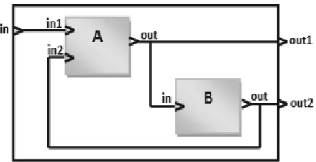
Figure 2.Graphical representation of a coupled model consisting of two atomic models.
3.1.3. The DEVS modelling
The multitude of modelling tools and the de-sire to reuse existing models have stimulated researchers to guide their work to the standard-ization of the tools to be used. The DEVS for-malism seems to be well suited for this mission. The strength of DEVS is summed up in its abil-ity to express, thanks to the concept of abstrac-tion applied to each level, ranging from atomic models to a collaboration of a set of models where each model interacts with the others. Although independent of the implementation, DEVS provides a modular and hierarchical vi-sion of dynamic models. Events generated by a model can take values in various fields and can be stimuli for other models. Thus, accord-ing to B. P. Zeigler [10-11], we can prove that there is a DEVS model for all discrete events systems. But we can go further. In fact, DEVS can be ‘universal’ [43], allowing the coupling of models and formalisms described as hetero-geneous paradigms. The main idea is that the models are considered as black boxes that have no link with the outside world except through input and output ports to exchange events and values. With this feature abstraction, several models can be coupled while enjoying the reuse of existing models. It is also possible to perform
formal verification of DEVS models, which is a valuable aid in the design of systems [44]. Coupling models based on DEVS is a typical task. However, non-DEVS models require ex-tra effort to be coupled. Two methods exist to incorporate a non-DEVS model in the DEVS: co-simulation and transformation[46]. Trans-formation of non-DEVS models to the DEVS comes in the way to specify models in a uniform language. Vangheluwe [9] represents the vari-ous possible transformations by using formal-ism transformation graph “FTG”. In the case of co-simulation, which is standardized, one con-siders the communication between simulators and not the model specifications. There are several works such as High Level Architecture (HLA) [47]which come into this framework.
3.2. The Multi-Agent Systems (MAS)
The multi-agent approach is at the root of the connection of several specific domains of artifi-cial intelligence, distributed computing systems and software engineering. It is a discipline that focuses on collective behavior produced by the interactions of several autonomous and flexible entities called agents. These interactions turn around the cooperation, competition or coexis-tence between these agents. A multi-agent sys-tem (MAS) is a distributed system consisting of a set of interacting agents. It is [13], [ 48-49]generally characterized by: each agent has limited information and problem-solving abili-ties and each agent has an individual space(its environment)and a partial view of a distributed space(sharing environment);
• There is no overall control of multi-agent
system.
• Data are decentralized.
• Calculations are asynchronous.
• The agents can interact by transmitting mes-sages or by producing and consuming data via shared memories(blackboards).
J. Ferber [13] defines components of MAS as follows:
• An identified environment provided with a
• A set of passive objects that can be perceived, created, modified or destroyed by agents.
• A set of active agents.
• A set of relations that link objects between them.
• A set of operations that provide the
oppor-tunity for the agents to perceive, produce, consume, transform and manipulate objects.
• A set of universal laws which are operators
responsible for representing the application of agent actions on the world and the world’s reaction to these actions.
3.2.1. AALAADIN model
With AALAADIN [14, 15], one can describe
multi agent systems with different forms of or-ganizations such as market-like or hierarchical organizations and therefore it could be use-ful for designing MAS. The organization in AALAADIN is a framework for the activity and interaction through the definition of groups, roles and their relationships. Figures 3 and 4 re-present the diagrams of this model. AALAADIN
uses the concept of AGR (Agent, Group and
Role):
Agent: An agent is only specified as an active communicating entity which plays roles within groups. The model places no constraints on the internal architecture of the agents. Figure 3 represents the Agent model.
Figure 3.Basic architecture of an agent.
Group: Groups are defined as atomic sets of agent aggregation representing any usual multi-agent system. Each multi-agent is part of one or more groups. In AALAADIN, groups can freely overlap.
Role: The role is an abstract representation of an agent function, service or identification within a group.
Each agent can handle multiple roles, and each role handled by an agent is local to a group. Figure 4 represents the diagram of AALAADIN model.
Figure 4. Agent/Group/Role model.
4. Simulated Industrial System
Our implementation concerns the simulation of an industrial regulation system (Steam Gener-ator)used in industrial petroleum process [ 50-51]. In this section, we will show this process.
Two major components compose the process: the feeding water which provides appropriate quantities of water as requested by the second entity: the boiler, which generates the steam as required for other industrial processes ( turbo-compressors, turbines...). Figures 5 and 6 illus-trate this system.
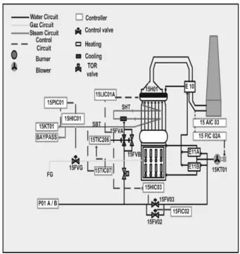
Figure 6.Technical drawing of the steam generator.
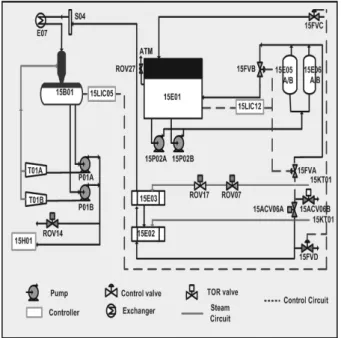
4.1. The Feed Water Station
This station supplies the steam generator with feeding water, it includes:
• The condenser(15E01).
• The degasser(15B02).
• The feed water tank(15B01).
4.1.1. Circuit description
The extracting water comes from the condenser (15E01)by the bottom, it gets through a valve and a mesh filter before its inhalation by the pumps(15 PM 02 A/B). This water is inhibited with 12 bars towards the maintaining ejectors (15 E 05 A/B)and it will feed the heaters while passing by the valve(15 FVA)towards the de-gasser (15B02) and the valve (15FVB) turns back towards the condenser.
Those two valves functions are in split range and controlled by the regulator (15 LIC12) (level 15 E01). Then, the water crosses the valves (15 ACV 06 A/B): A towards the heaters and B towards the channel).
The valve(15 FVD)goes towards U50 and the valve(15 FVA)supplement of Unit 50 towards the condenser(15E 01)and they are controlled in split range by the regulator (15 LIC 05) in order to maintain a constant level in the feed water tank.
The extracting water is then conducted towards the controllers(15 E 02 and 03)in contact with steam racking 2 and 3 of the steam circuit(15 KT 01). The two heaters are provided with By-pass, the extracting water goes then to feed the degasser while crossing through a chain valve with auto clean filter.
The level of water in the condenser (15E01) is regulated to 65% by a loop of regulation 15 LIC 12. The level of water in the feeding tank (15B01)is regulated to 65% by a loop of regu-lation 15 LIC05.
4.2. The Steam Generator
A boiler is a steam generator; it aims to raise the temperature of water until changing its status, that is to say, to become steam, and then to bring it to proper defined pressure and temperature. Regarding boiler’s construction, we distinguish:
• Boiler making: tubes return box, screens,
atomizer, super-heaters and drums
• The combustion chamber: burners, air
cir-cuits and auxiliaries.
4.2.1. Principle of operation
The water is brought to the boiler by a feeding-water pump. The power of the boiler is featured by intensity of steam expressed in kilograms produced per hour.
gases. The air flow is regulated according to the fuel, to have a complete combustion.
The feeding of water is done starting from a pump controlled by two valves mounted in par-allels, the first one is used to fill the tank and the other one for regulation purpose (body of adjustment/regulation); from where it comes out to go then by an economizer in order to be heated by the calories of the evacuated smoke and returns finally to the higher tank to produce the steam.
The saturated steam comes out from the higher tank, goes by the super heater(in the hearth), its temperature increases while its pressure varies slightly. At the end, the final temperature of the produced steam will be regulated. This dry steam is also called load of the boiler.
4.2.2. Regulations which ensure the generation of steam
Five conditions are required to ensure a proper production of steam:
1. Regulation of heating(a correct air-gas fac-tor).
2. Control of combustible flow(15FVG). 3. Control of air flow(15KT01).
4. Regulation of balloon level(15H01)to 50%. 5. Control of superheated steam temperature
(495◦C).
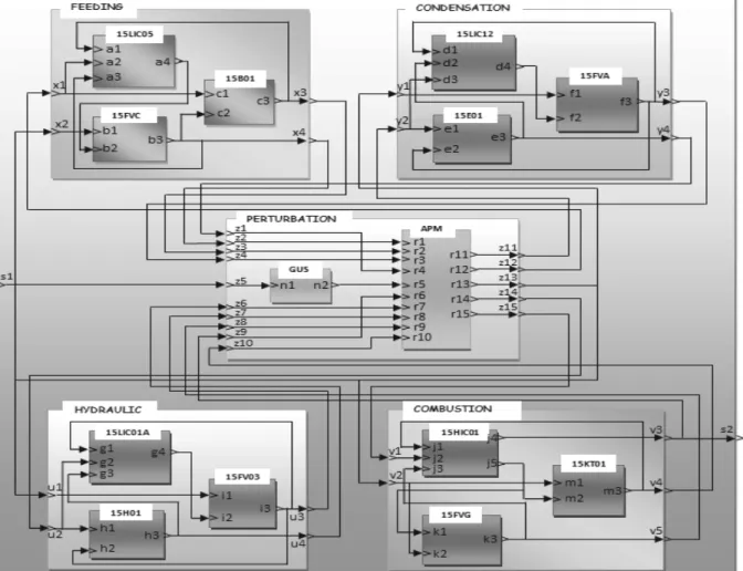
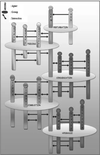
4.3. DEVS Model of the Industrial Simulator
To model our system, we have used primarily the DEVS formalism; therefore, we have split up our process into four models. Each coupled model is composed of a set of atomic models. Figure 7 represents the overall structure of the simulator based on the suggested DEVS model. The release of disturbances is done by the op-erator which controls the system by getting in-structions from the load(i l)1of the simulator.
4.3.1. The feeding coupled model
Decomposition on atomic DEVS models of the feeding coupled ensures the operation of water feeding:
• Model (15LIC05): Shows the regulator
(15LIC05). Its role consists of the control of the tank. The regulator(15LIC05)sends the orders of opening and closing(o fw) to-wards the 15FVC valve until the measured level is equal to the desired level(65%).
• Model (15B01): Shows the tank (15B01). Its role consists of checking the level of wa-ter(t l)in the tank.
• Model (15FVC): Shows the valve
(15FVC). This valve controls water flow
(c w f)entering the condenser.
4.3.2. The condensation coupled model
Decomposition of the condensation coupled mo-del into a set of atomic DEVS momo-dels to carry out the condensation operation of water.
• Model (15LIC12): Shows the regulator
(15LIC12). Its role consists of the control of the condenser. The regulator(15LIC12) sends the orders of opening and closing sys-tem (o cn) towards 15FVA valve until this measured level is equal to the desired level (65%).
• Model (15E01): Shows the condenser
(15E01). Its role consists of checking the variation of water level (c l) in the con-denser.
• Model (15FVA): Shows the valve
(15FVA). Its role is to control the water flow (t w f)coming out towards the tank.
4.3.3. The combustion coupled model
This model is formed by a set of atomic DEVS models making it possible to carry out the com-bustion operation:
• Model (15HIC01): Shows the regulator
(15HIC01). Its role is to control the com-bustion and to adjust the steam flow (v f).
In fact, if this flow is not consistent to the load of the boiler, it sends orders of opening and closing(o cm) towards the Turbo-fans
(15KT01)and to the valve 15FVG in order
to reach the desired sizes.
• Model (15KT01): Shows the Turbo-fan
(15KT01). Its role is to control the air flow (a f).
• Model (15FVG): Shows the valve
(15FVG). Its role is to control the gas flow (g f).
4.3.4. The Hydraulic coupled model
• Model (15LIC01A): Shows the regulator
(15LIC01A). Its role is to regulate the level of the tank. It sends the commands for open-ing and closopen-ing (o hy) towards the valve
15FV03 until this measured level equals the desired level(50%).
• Model (15FV03): Shows the valve
(15FV03). Its role is to control the feed-ing water flow(w f)coming from the water station.
• Model (15H01): Shows the tank (15H01). Its role is to calculate the level of the balloon (b l) by using the values provided by the regulator(15HIC01)and the valve 15FV03.
• In addition to these models, we consider
two others: the APM model which provides internal system cooperation and monitoring and the graphical user interface GUS which provides the data inputs, outputs and con-trols. These DEVS models constitute the perturbation coupled model.
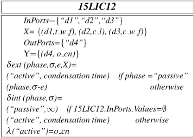
4.4. An Atomic Model Behaviour and DEVS Specification Example
In order to give a practical example of the be-havior of the modeled system, let us consider the regulator 15LIC12 illustrated in Figure 7. Initially, this component is in phase “passive”, when a news t w f, c l and c w f respectively arrive on the inputs ports “d1, d2, d3” it goes to regulate the condensation. This is achieved
by the sentence “hold-in active condensation
time”, which sets the phase toactiveand sigma tocondensation time. Such handling of incom-ing values is represented in the external tran-sition function, when a value arrives while the regulator is in “active” phase, it simply ignores it. This is achieved by the “continue” sentence which updates sigma to reflect the passage of elapsed time(ta), but otherwise leaves the state unchanged. When the regulator has finished regulation, it places the orders (o cn) on port “d4” and returns to the “passive” phase. Send-ing of the orders is done by the output function which is called just before the state transition function. The latter contains the sentence “pas-sive” which returns the model to the idle state in which the phase is “passive” and sigma is “infinity”. All the other models of our system follow the same way of representation. Thus, the DEVS specification of the 15LIC12 regula-tor is represented in Table 1.
15LIC12
InPorts={“d1”,“d2”,“d3”}
X={(d1,t w f), (d2,c l), (d3,c w f)}
OutPorts={“d4”}
Y={(d4, o cn)}
ext (phase,,e,X)=
(“active”, condensation time) if phase =“passive”
(phase,-e) otherwise
int (phase,)=
(“passive”,∞) if 15LIC12.InPorts.Values=∅
(“active”, condensation time) otherwise (“active”)=o cn
Table 1.The DEVS specification of the 15LIC12 regulator.
The DEVS formal specifications of all the atomic and coupled models of the simulator are summed up in Appendix 1 and Appendix 2, respectively.
5. Using Multi-agent System
This section is devoted to the system imple-mentation. The models, previously obtained and formally verified and validated in DEVS, are developed by using the AALAADIN orga-nizational model[14],[15].
AALAADIN focuses on the analysis, design and formalization of multi-agent systems in an organizational perspective. It is based on the conceptual model(AGR)by using the concepts of agents, groups and roles[12].
In the present multi-agent design, we have re-tained the same decomposition of the system into atomic and coupled models. Thus, cou-pled DEVS models are represented by groups of agents and atomic models by agents.
The decomposition of agents, groups and roles played by agents between the groups is obtained in conformity with the DEVS decomposition based itself on the elementary components of the system which formed the atomic models. DEVS specification gives a rigorous and math-ematical scheme of the formal structure and dy-namical behaviour of each of these components. The second step, shown here, concerns the sys-tem implementation.
We use MAD-KIT platform as a programming environment in order to have executable codes and data structures concerning our system. Thus, to have an operational simulator, we take ad-vantage of the flexibility as well as of the well adapted tools provided by the MAD-KIT envi-ronment.
Table 2 presents these groups and agents. The roles played by the different agents are defined previously, by using DEVS specification, par-ticularly the transitions between the states when specific events occur.
Practically, the atomic models are represented by agents, the coupled models by groups, the roles represent the states evolutions of the model, the inputs and outputs are materialized by inter-actions between agents or groups.
this approach to resolve only the application considered here. We are working actually to generalize this approach for other industrial sys-tems and particularly the petroleum processes.
Groups Agents
Perturbation group APM, GUS Feeding group 15FVC, 15B01, 15L1C05 Condensation group 15FVA, 15E01, 15LIC12
Combustion group 15FV0, 15KT01, 15HIC01 Hydraulic group 15H01, 15FV03, 15LIC01
Table 2.Groups and agents.
Figure 8 presents the organizational
AALAADIN design of the system to be mod-eled: agents, groups and interactions between agents and groups are clearly expressed.
Figure 8.Organizational system.
5.1. Implementation of the System
The MAD-KIT platform is a software environ-ment which offers advanced tools for agents managing the use of the concepts of AGR. The MAD-KIT MAS platform is based on the AALAADIN organizational model.
MAD-KIT is a set of packages of Java classes that implements the agent kernel, several li-braries of messages, probes and agents. Tools for graphical development environment and stan-dard agent models are included in MAD-KIT. This environment allows us to implement all the DEVS models by using MAS modelling. Inter-actions and communication between the agents are realised by message passing.
Algorithms 1, 2 and 3 below give some exam-ples of java codes.
Algorithm 1:Implementation of the 15LIC05 regulator public class15LIC05extendsatomic{
protected floatw f, c w f; protectedinto wf, i l, t l;
protected doubleregulation fee time; protected Stringinput;
public15LIC05(String name, double Regulation fee time)}
super(name); addInport(“a1”); addInport(“a2”); addInport(“a3”); addInport(“a4”); addOutport(“a5”); phases.add(“active”);
regulation fee time=Regulation fee time;
}
public voidinitialize(){
phase=“passive”; sigma=INFINITY; o fw=0//closing input=new String(“in”); super.initialize();
}
5.2. Sending Messages
The method sendMessage(AgentAddress,
mes-sage) is the most basic and lowest level. It
allows sending the message “message” to the agent at “AgentAddress” which may be obtained by another agent by requesting either group or the role. This method accepts two parameters:
• The first one is AgentAddress type that al-lows a unique identification of the address of the receiving agent; we get back thanks to the method:getAgentWithrole(group, role).
• The second parameter shows the message to
be sent; theObjectMessageclass, for exam-ple, allows sending any object which gives great freedom to the programmer to compose the message.
Example:
Algorithm 2 shows how the 15FVA agent sends the new water flow(t w f)coming out towards the tank to the agent regulator 15LIC12:
Algorithm 2:Sending message
voidsend measurement()
{
valmes=new Val(); mes.setv1(t w f); mes.settype(“(t w f”);
ObjectMessageobj=
newObjectMessage((Object)mes);
AgentAddressadr=
getAgentWithRole(“condensation”,“agent 15LIC12”);
sendMessage(adr,obj);
. . .
}
5.3. Receiving Messages
Each agent has a private mailbox in which the kernel posts messages, at the lowest level; there are two methods of receiving messages:
• is Message Box Empty (): Checks if the agent has not read his mailbox messages, which returns true if it is empty and if there are unread messages it returns false.
• next Message (): Method of recovering the first unread, which is then removed from the message box.
Example:
The portion of the following code shows the use of such methods by the 15L1C05 agent:
Algorithm 3:Receiving message
public voidt msg()
{while(!isMessageBoxEmpty()) }
msg 15L1C05=(ObjectMessage)nextMessage(); traiting message(msg 15L1C05);
} }
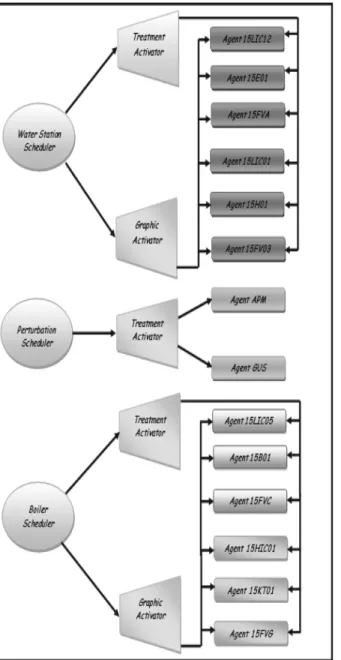
5.4. Execution Policy
Within multi-agent systems, it is necessary to manage a wide number of granularity agents enough thin and to control their scheduling. It is almost impossible if we based on a process mechanism due to induced overload. In this case, we use “synchronous” agents via external agents that will define their synchronous execu-tion policy. For the purpose of execuexecu-tion policy implementation, we set two levels: scheduler and activator.
The scheduling under MAD-KIT type is del-egated to the agents inheriting the scheduler class. A scheduler agent aims to coordinate the execution of agents through generic objects tools called activators; the latter are the means for the scheduler to identify a set of agents. The code of an activator has all the methods of other agents that will be set forth while it is acti-vated by the scheduler agent. It should be noted here, that the methods set forth by activators are those of the agents which inherit the Abstract-Agent and implement the ReferenceableAgent interface, and not the agents which inherit from the Agent class.
Indeed, the use of the schedulers and the activa-tors reduces the rate of processor’s use by sys-tem agents; moreover, their use provides more flexibility.
• An activator which executes the code of APM agent.
• An activator which executes the code of GUS
agent.
• Two activators, one for processing purpose
and another for graphic display, which exe-cutes water station agents.
• Two activators, one for processing purpose
and another for graphical display which ex-ecute boiler agents.
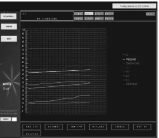
Figures 9, 10, 11 and 12 show the interfaces obtained for user-system interaction.
Figure 9.Structure of the simulator scheduler.
Figure 10. Interface of water station section of the simulator.
Figure 11. Interface of the curves of the water station simulator.
Figure 13. Interface of the curves of the steam generator simulation.
5.5. The Use of the System
The user has a set of control and data inputs to initialize the system in several modes, the sys-tem runs according to these data. The states of the system are displayed on the synopsys in real time.
The user can launch the simulation by pressing the buttons TO WATER S and TO BOILER. Therefore these buttons will give him the pos-sibilities of rocking the interfaces of the water station section and the boiler section. It can seize the load of the system in the text field. The results of simulation can be presented by curves with CURVES Button. A real time sim-ulation is executed, as shown in Figures 10 and 12 which represent the water station and the boiler (see the technical diagram, in Figures 5 and 6)Thus, the user can pilot the operation of steam regeneration and (water)feeding of the boiler with water demineralized by publishing different data of regulation(c w f, t l, c l, g f, t w f,...) and can follow the system evolutions. These data are presented graphically by curves (see Figures 11 and 13).
6. Conclusion
The objective of our simulation is to use rigor-ous formalisms and tools for a good representa-tion of a complex industrial system process.
In this work, we have built a simulator of an industrial process. Use of this system is ded-icated principally for training beginner opera-tors, workers and new recruits, enabling them to understand and to simulate the system without acting on the real system and without stopping processes. This simulator saves time and money and prevents potential damages to the real sys-tem through manipulation. For the design and implementation of the system, we opted for a hybrid method that combines DEVS and multi-agent platform MAD-KIT.
Actually, we are working on the generalization of the idea developed in this paper and we aim to propose a general method for building simula-tors able to operate on many classes of industrial systems.
References
[1] L. V. BERTALANFFY,Th´eorie g´en´erale des syst`emes. Dunod, 1968.
[2] H. A. SIMON, The sciences of the artificial.
Cam-bridge(MA), MIT Press, 1969.
[3] P. A. FISHWICK,Simulation Model Design and
Ex-ecution. Building Digital Worlds. Prentice Hall, 1995.
[4] M. SONNESSA, Modelling and simulation of
com-plex systems. Doctoral dissertation, PhD Thesis in “Cultura e impresa”, University of Torino, Italy, 2004.
[5] R. E. SHANNON, Simulation modelling and method-ology.Proceedings of the 76th Bicentennial Con-ference on Winter Simulation,(1976), pp. 9–15. [6] R. G. INGALLS, Introduction to simulation.
Proceed-ings of the 33rd Conference on Winter Simulation, IEEE Computer Society,(2001), pp. 7–16.
[7] R. E. SHANNON, Introduction to the art and science
of simulation. Proceedings of the 30th Confer-ence on Winter Simulation, IEEE Computer Society Press,(1998), pp. 7–14.
[8] P. A. FISHWICK, Computer simulation: growth
through extension.Transactions of the Society for Computer Simulation International,14(1) (1997), 13–23.
[9] H. VANGHELUWE, Foundations of modelling and
simulation of complex systems.Electronic Commu-nication of the EASST, 10: Graph Transformation and Visual Modeling Techniques,(2008).
http://eceasst.cs.tuBerlin.de./index. php/eceasst/issue/view/19
[10] B. P. ZEIGLER,Theory of Modeling and Simulation.
[11] B. P. ZEIGLER, T. G. KIM, H. PRAEHOFER, Theory
of Modeling and Simulation. Academic Press, Inc., Orlando, FL, USA, 2000.
[12] O. GUTKNECHT, J. FERBER, The MadKit agent
platform architecture. Laboratoire d’Informatique, Robotique et Micro´electronique de Montpellier, (2000).
[13] J. FERBER, Les syst`emes multi-agents: vers une
intelligence collective. Informatique, Intelligence Artificielle, Intereditions, Paris,(1995).
[14] J. FERBER, O. GUTKNECHT, Aalaadin: a meta-model
for the analysis and design of organizations in multi-agent systems.ICMAS (International Conference on Multi-Agent Systems)(Y. DEMAZEAU, Ed.),(1998)
pp. 128–135. IEEE Press, Paris.
[15] F. MICHEL, J. FERBER, O. GUTKNECHT, Generic
Simulation Tools Based on MAS Organization. LIRMM Laboratoire d’Informatique, Robotique et Micro´electronique de Montpellier,(2001).
[16] A. M. UHRMACHER, B. SHATTENBERG, Agents in Discrete Event Simulation.in Proceedings of ESS98, (1998).
[17] J. HIMMELSPACH, M. R ¨OHL, A. M. UHRMACHER,
Component based modelling and simulation for valid multi-agent system simulations.International Journal for Applied Artificial Intelligence, 24(5) (2010), 414–442.
[18] J. HIMMELSPACH, JAMES II: Extending, Using, and
Expeiments. In Proceedings of the 5th Simutools
Conference ICST,(2012), pp. 208–210.
[19] D. WEYNS, H. VANDYKEPANURAK, F. MICHEL, T.
HOLVOET, J. FERBER, Environments for Multi-agent
Systems State of the Art and Research Challenges. In Environments for Multi-agent Systems(D. WEYNS,
H. DYKEPANURAK, F. MICHEL, Eds.), vol. 3374
of Lecture Notes in Computer Science, pp. 1–47, (2005)Berlin, Heidelberg: Springer Berlin Heidel-berg.
[20] D. WEYNS, M. SCHUMACHER, A. RICCI, M. VIROLI,
T. HOLVOET, Environments in Multi-agent Systems.
The Knowledge Engineering Review,20(2) (2005).
[21] M. WOOLDRIDGE, An introduction to Multi-agent
Systems. 2nd ed., John Wiley & Sons, Chistester,
UK, 2009.
[22] A. STEINIGER, F. KRUGER¨ , A. M. UHRMACHER,
Modeling Agents and Their Environment. In Multi-level-DEVS, Proceedings of the Winter Simulation Conference,(2012).
[23] J. DAVILLA, M. UZCATEGUI, GALATEA: A
Multi-agent simulation platform. InInternational Confer-ence on Modelling, Simulation and Neural Networks MSNN’2000,(2000)M´erida, Venezuela.
[24] J. DAVILLA, E. GOMEZ, K. LAFAILLE, K. TUCCI,
M. UZCATEGUI, MultiAgent Distributed Simulation
with GALATEA. Proceedings of the 2005 Ninth IEEE International Symposium on Distributed Sim-ulation and Real-Time Applications (DS-RT’05), (2005).
[25] S. MATTEI, P. A. BISGAMBIGLIA, M. DELHOM, E.
VITTORI, Towards Discrete Event Multi Agent
Plat-form Specification, Computation Tools.The Third International Conference on Computational Logics, Algebras, Programming, Tools, and Benchmarking, (2012), pp. 14–21.
[26] E. RAMAT, P. PREUX, Virtual Laboratory Environ-ment(VLE): a software environment oriented agent and object for modeling and simulation of complex systems. Simulation and modeling practice and theory,11(1) (2003), 45–55.
[27] G. QUESNEL, R. DUBOZ, E. RAMAT, The Virtual
Laboratory Environment – An operational frame-work for multi-modelling and analysis of complex dynamical systems.Simulation and modeling prac-tice and theory,17(4) (2009), 641–653.
[28] A. ILACHINSKI,Cellular Automata, a Discrete
Uni-verse. World Scientific Publishing Co, 2001. [29] G. A. WAINER, N. GIAMBIASI, Application of the
Cell-DEVS Paradigm for Cell Spaces Modelling and Simulation.Simulation,76(1) (2001), 22–39. [30] G. A. WAINER, P. MOSTERMAN, Discrete-Event
Modeling and Simulation: Theory and Applica-tions. Taylor and Francis Group, 2011.
[31] S. H. SARJOUGHIAN, B. P. ZEIGLER, The role of
collaborative DEVS modeler in federation develop-ment. InProceedings of the 99th System Interoper-ability Workshop,(1999).
[32] E. KOFMAN, N. GIAMBIASI, S. JUNCO, Fdevs: A
general DEVS based formalism for fault modeling and simulation.European Simulation Symposium, vol. 1,(2000)Hamburg, pp. 77–82.
[33] D. R. HILD, Discrete Event System Specification (DEVS), Distributed Object Computing, Modeling and Simulation. PhD thesis, University of Arizona, 2000.
[34] A. ANGLANI, P. CARICATO, A. GRIECO, F. NUCCI, A.
MATTA, G. SEMERARO, T. TOLIO, Evaluation of ca-pacity expansion by means of fuzzy-devs.14th Eu-ropean Simulation Multi Conference,(2000)Gent, Belgium.
citeseer.ist.psu.edu/499458.html
[35] J. B. FILIPPI, F. BERNARDI, M. DELHOM, The JDEVS environmental modeling and simulation environ-ment.IEMSS, Integrated Assessment and Decision Support,(2002)Lugano, Suisse, pp. 283–288.
[36] H. VANGHELUWE, The Discrete EVent System
speci-fication DEVS Formalism.Technical report,(2001). http://moncs.cs.mcgill.ca/
[37] C. JACQUES, G. A. WAINER, Using the cd++DEVS
tookit to develop petrinets. InSCS, Proceedings of the SCS Conference,(2002).
[38] A. HAMRI, N. GIAMBIASI, C. FRYDMAN, Min-Max
[39] F. BARROS, Dynamic structure discrete event
sys-tem specification: a new formalism for dynamic structure modelling and simulation. InProceedings of the Winter Simulation Conference,(1995). [40] A. M. UHRMARCHER, Dynamic Structures in
Mod-eling and Simulation: A Reflective Approach.ACM Transactions on Modeling and Computer Simula-tion,11(2001), 206–232.
[41] L. NTAIMO, B. P. ZEIGLER, Expressing a forest cell
model in parallel DEVS and timed cell-DEVS formalisms.Proceedings of the 2004 Summer Com-puter Simulation Conference,(2004).
[42] A. TROCCOLI, G. A. WAINER, Implementing
paral-lel cell-DEVS. In IEEE, Proceedings of the 36th Annual Simulation Symposium,(2003).
[43] L. TOURAILLE, M. K. TRAORE´, D. R. C. HILL,
SimStudio: une Infrastructure pour la mod´elisa-tion, la simulation et l’analyse de syst`emes dy-namiques complexes.Research Report LIMOS/RR-10-13,(2010).
[44] R. FREIGASSNER, H. PRAEHOFER, B. P. ZEIGLER,
Systems approach to validation of simulation mod-els.Cybernetics and Systems,(2000), 52–57. [45] J. H. BYUN, C. B. CHOI, T. G. KIM, Verification of
the DEVS model implementation using aspect em-bedded DEVS. In Proceedings of the 2009 Spring Simulation Multi Conference, (2009) San Diego, USA.
[46] D. C. SCHMIDT, Model-Driven Engineering Guest Editor’s Introduction IEEE Computer, 39(2) (2006), 25–31.
[47] Simulation Interoperability Standards Committee, IEEE Standard for Modelling and Simulation (M&S)High Level Architecture(HLA)– Frame-work and Rules,IEEE Std 1516,(2000).
[48] J. FERBER,Multi-Agent Systems: An Introduction to
Distributed Artificial Intelligence. Addison-Wesley Longman Publishing Co. Inc. Boston, MA, USA, 1999.
[49] E. V. KRISHNAMURTHY, V. K. MURTHY, Distributed
agent paradigm for soft and hard computation. Jour-nal of Network and Computer Applications,29(2) (2006), 124–146.
[50] N. SEDDARI, M. REDJIMI, Multi-Agent Modeling of
a Complex System. InIEEE 3rdInternational
Con-ference on Information Technology and e Services (ICITeS),(2013)Sousse, Tunisia.
[51] N. SEDDARI, M. REDJIMI, Operational approach to
modelling and simulation of an industrial process. In IEEE International Conference on Computer Application Technology (ICCAT), (2013) Sousse, Tunisia.
Received:January, 2014
Revised:July, 2014
Accepted: August, 2014
Contact addresses: Noureddine Seddari Department of Computer Science Faculty of Sciences University 20 August 1955 Algeria
e-mail:[email protected]
Mohammed Redjimi Department of Computer Science Faculty of Sciences University 20 August 1955 Algeria
e-mail:[email protected]
Sofiane Boukelkoul Department of Computer Science Faculty of Sciences University 20 August 1955 Algeria
e-mail:[email protected]
NOUREDDINESEDDARIobtained his Master degree in computer science from Universit´e 20 Aout 1955, Skikda, Algeria in 2011. He is a PhD student at the same university. His research interests include modelling and simulation of complex systems, MAS concepts and platforms and DEVS formalisms.
MOHAMMEDREDJIMIis an associate professor of computer science at the Universit´e 20 Aout 1955, Skikda, Algeria. He obtained his PhD in computer science from the Universit´e des Sciences et des Techniques de Lille I, France in 1984. He was an associate teacher and researcher at the same university(1982 to 1986). He obtained the postdoctoral degree
(Habilitation Universitaire)from Universit´e Badji Mokhtar, Annaba, Algeria in 2007. He was Head of Computer Science Department and Dean of Engineering and Sciences Faculty at the Universit´e 20 Aout 1955, Skikda, Algeria. M. Redjimi has several publications in inter-national journals and conferences. He is reviewer in several interna-tional journals and conferences. M. Redjimi is currently Head of the team: modeling and simulation of complex systems at the Laboratoire d’Informatique et de Communication de l’Universit´e de Skikda( LI-CUS)– Universit´e 20 Aout 1955, Skikda, Algeria. His current research interests include image processing, complex systems, modelling and simulation, MAS concepts and platforms and DEVS formalisms.
Appendix 1: Atomic DEVS specifications of the system
S={“active”,“passive”}×R+0 and ta(phase,)=for all atomic models of the system.
APM GUS
InPorts={"r1", "r2","r3","r4","r5", r6","r7","r8","r9", "r10"}
X ={( r1, c_w_f), ( r2,t_l ), ( r3, t_w_f ),( r4,c_l ), ( r5,i_l),( r6,v_f ), ( r7,b_l), ( r8,w_f ), ( r9,g_f ), ( r10,a_f )}
OutPorts = {"r11", "r12","r13", "r14", "r15"} Y={( r11, c_w_f ), ( r12, w_f ), ( r13, o_s ), ( r14, v_f ), ( r15, i_l )}
įext (phase, ı, e, X) =
("active",regulating time) if phase = “passive” (phase, ı-e) otherwise įint ( phase, ı ) =
(" passive ", ) if APM.InPorts.Values= Ø ("active", regulating time) otherwise Ȝ (" active ") = c_w_f, w_f, v_f, i_l and o_s
InPorts={"n1"} X = {( n1,i_l )} OutPorts ={"n2"} Y={(n2,i_l )} įext (phase, ı, e, X) =
("active", perturbation time) if phase = “passive” (phase, ı-e) otherwise įint ( phase, ı ) =
(" passive ",) if GUS.InPorts.Values= Ø ("active", perturbation time) otherwise Ȝ (" active ") = i_l
15LIC05 15B01
InPorts={"a1", "a2","a3"}
X ={( a1,t_l ), ( a2, w_f ), (a3,c_w_f )} OutPorts = {"a4"}
Y={( a4, o_wf )} įext (phase, ı, e, X) =
("active", feeding time) if phase = “passive” (phase, ı-e) otherwise įint ( phase, ı ) =
(" passive ", ) if 15LIC05.InPorts.Values= Ø ("active", feeding time) otherwise
Ȝ (" active ") = o_fw
InPorts={"c1", "c2"} X ={( c1,w_f ), ( c2,c_w_f ) } OutPorts = {"c3"}
Y={( c3, t_l )} įext (phase, ı, e, X) =
("active", t_l calculation time) if phase = “passive” (phase, ı-e) otherwise įint ( phase, ı ) =
(" passive ", ) if 15B01.InPorts.Values= Ø ("active", t_l calculation time time) otherwise Ȝ (" active ") = t_l
15FVC 15LIC12
InPorts={"b1", "b2"} X ={( b1,o_s), ( b2,o_fw )} OutPorts = {"b3"} Y={(b3, c_w_f) } įext (phase, ı, e, X) =
("active", c_w_f calculation time) if phase = “passive” (phase, ı-e) otherwise įint ( phase, ı ) =
(" passive ",) if 15LIC12.InPorts.Values= Ø ("active", c_w_f calculation time) otherwise Ȝ (" active ") = c_w_f
InPorts={"d1", "d2","d3"}
X ={( d1,t_w_f ), (d2,c_l ),( d3, c_w_f )} OutPorts = {"d4"}
Y={(d4, o_cn )} įext (phase, ı, e, X) =
("active", condensation time) if phase = “passive” (phase, ı-e) otherwise įint ( phase, ı ) =
(" passive ",) if 15LIC12.InPorts.Values= Ø ("active", condensation time) otherwise
Ȝ (" active ") = o_cn
15E01 15FVA
InPorts={"e1", "e2}
X ={( e1,c_w_f ), (e2,t_w_f )} OutPorts = {"e3"}
Y={(e3, c_l )} įext (phase, ı, e, X) =
("active", c_l calculation time) if phase = “passive” (phase, ı-e) otherwise įint ( phase, ı ) =
(" passive ",) if 15E01.InPorts.Values= Ø ("active", c_l calculation time) otherwise Ȝ (" active ") = c_l
InPorts={" f1"," f2"} X ={( f1,o_s ), ( f2,o_cn )} OutPorts = {"f3"} Y={( f3, t_w_f )} įext (phase, ı, e, X) =
("active", t_w_fcalculation time) if phase = “passive” (phase, ı-e) otherwise įint ( phase, ı ) =
15HIC01 15KT01
InPorts={" j1", " j2", " j3"} X ={( j1,a_f ), ( j2,i_l ), ( j3, g_f )} OutPorts = {" j4 ", " j5"}
Y={( j4,v_f ), ( j5,o_cm )} įext (phase, ı, e, X) =
("active", combustion time) if phase = “passive” (phase, ı-e) otherwise įint ( phase, ı ) =
(" passive ",) if 15HIC01.InPorts.Values= Ø ("active", combustion time) otherwise Ȝ (" active ") = v_fand o_cm
InPorts={" m1", " m2"} X ={( m1,o_s ), ( m2,o_cm )} OutPorts = {"m3"}
Y={(m3, a_f ) } įext (phase, ı, e, X) =
("active", a_f calculation time) if phase = “passive” (phase, ı-e) otherwise
įint ( phase, ı ) =
(" passive ", ) if 15KT01.InPorts.Values= Ø ("active", a_f calculation time) otherwise Ȝ (" active ") = a_f
15FVG 15LIC01A
InPorts={" k1", " k2"} X ={( k1,o_cm ), ( k2,o_s )} OutPorts = {"k3"}
Y={( k3, g_f )} įext (phase, ı, e, X) =
("active", g_f calculation time) if phase = “passive” (phase, ı-e) otherwise įint ( phase, ı ) =
(" passive ",) if 15FVG.InPorts.Values= Ø ("active", g_f calculation time) otherwise Ȝ (" active ") = g_f
InPorts={"g1", "g2","g3"}
X ={( g1,w_f ), ( g2, v_f ), ( g3, b_l)} OutPorts = {" g4"}
Y={( g4, o_hy )} įext (phase, ı, e, X) =
("active", hydraulic time) if phase = “passive” (phase, ı-e) otherwise įint ( phase, ı ) =
(" passive ", )if 15LIC01A.InPorts.Values= Ø ("active", hydraulic time) otherwise Ȝ (" active ") = o_hy
15FV03 15FV03
InPorts={" i1", " i2"} X ={( i1,o_s ), ( i2,o_hy )} OutPorts = {"i3 "} Y={( i3, w_f ) } įext (phase, ı, e, X) =
("active", w_f calculation time) if phase = “passive” (phase, ı-e) otherwise
įint ( phase, ı ) =
(" passive ",) if 15FV03.InPorts.Values= Ø ("active", w_f calculation time) otherwise Ȝ (" active ") = w_f
InPorts={"h1", "h2"} X ={( h1,v_f ), ( h2,w_f ) } OutPorts = {"h3"} Y={( h3,b_l )} įext (phase, ı, e, X) =
("active", b_l calculation time) if phase = “passive” (phase, ı-e) otherwise
įint ( phase, ı ) =
Appendix 2: Coupled DEVS specifications of the system
SIMULATOR(SIM) PERTURBATION(PER)
InPorts={"s1"} X ={( s1, i_l )} OutPorts= {"s2"} Y={(s2, v_f )}
D ={FEE, PER, CON, COM, HYD} MFEE =FEDDING
MPER =PERTURBAT- ION MCON =CONDENSAT-ION MCOM =COMBUSTION MHYD =HYDRAULIC EIC ={(SIM , s1),(PER, z5)} EOC ={(COM, v3), ( SIM , s2)}
IC={((FEE,x3),(PER,z3)),((FEE,x4),(PER,z2)), ((CON,y3),(PER,z4)),((CON,y4),(PER,z1)), ((HYD,u3),(PER,z7)),((HYD,u4),(PER,z6)), ((COM,v3),(PER,z9)),((COM,v4),(PER,z10)),
((COM,v5),(PER,z8)),((PER,z11),(CON,y2)),((PER,z12), (FEE,x1)),((PER,z13),(CON,y1)),((PER,z13),
(COM,v2)),((PER,z13),(HYD,u1)),((PER,z13),(FEE,x2)), ((PER,z14), (HYD,u2)),((PER,z15),(COM,v1))}
InPorts = {"z1", "z2","z3", "z4", "z5","z6", "z7", "z8", "z9", "z10"}
X ={( z1, c_l ),( z2, c_w_f ), ( z3, t_l ), ( z4,t_w_f ), ( z5,i_l), (z6,b_l ),( z7,w_f ),( z8,g_f ), ( z9,v_f ), ( z10,a_f )}
OutPorts={"z11", "z12", "z13", "z14", "z15"}
Y={(z11, c_w_f), (z12,w_f ), (z13,(o_s),( z14,v_f ), ( z15,i_l )}
D= {GUS, APM } MGUS= DISTURBING MAPM= CONTROLLER
EIC= {((PER, z1), (APM,r4)), ((PER,z2), (APM,r1)), ((PER,z3), (APM,r2)),((PER,z4), (APM,r3)),((PER,z5), (GUS,n1)),((PER,z6), (APM,r7)),((PER,z7), (APM,r8)), ((PER,z8), (APM,r9)), ((PER,z9), (APM,r6)), ((PER, z10), (APM, r10)) }
EOC= {((APM, r11),(PER, z11)), ((APM, r12), (PER, z12)), ((APM, r13), (PER, z13)), ((APM, r14), (PER, z14)), ((APM, r15),(PER,z15)) }
IC ={(GUS,n2), (APM,r5) }
FEDDING(FEE) CONDENSATION (CON)
InPorts={"x1", "x2"} X ={( x1, i_l ), ( x2, o_s )} OutPorts= {"x3","x4"} Y= {(x3, t_l), (x4, c_w_f)} D= {15LIC05,15B01, 15FVC } M15LIC05=Regulator M15B01=Tank M15FVC=Water valve
EIC = {(( FEE , x1), (15LIC05,a2)),((FEE, x2), (15FVC, b1)), ((FEE, x1),(15B01,c1))}
EOC ={((15FVC, b3), (FEE,x4)), ((15B01, c3), ( FEE , x3))}
IC ={((15LIC05,a4), (15FVC,b2)), ((15B01,c3), (15LIC05,a1)),((15FVC,b3),(15B01,c2)), ((15FVC,b3), (15LIC05,a3)) }
InPorts= {"y1", "y2"} X = {(y1, o_s), (y2, c_w_f)} OutPorts= {"y3", "y4"} Y= {(y3, t_w_f), (y4, c_l)} D={15LIC12,15E01,15FVA } M15LIC12=Regulator M15E01= Condenser M15FVA = Water valve
EIC = {((CON, y2), (15LIC12, d3)), ((CON, y2), (15E01, e1)), ((CON, y1), (15FVA, f1))}
EOC = {((15E01, e3), (CON, y4)), ((15FVA, f3), (CON, y3))}
IC = {((15LIC12, d4), (15FVA, f2)), ((15FVA, f3), (15LIC12, d1)), ((15FVA, f3), (15E01, e2)), ((15E01, e3), (15LIC12, d2))}
COMBUSTION(COM) HYDRAULIC(HYD)
InPorts= {"v1", "v2"} X ={( v1, i_l ), ( v2, o_s )} OutPorts={"v3", "v4","v5"} Y={(v3, v_f ), (v4,a_f), (v5, g_f )} D={15HIC01,15KT01,15FVG } M15HIC01=Regulator M15KT01=Turbo-fan M15FVG =Gas valve
EIC = {((COM , v1), (15HIC01, j2), ((COM, v2),(15KT01,m1)), ((COM, v2),(15FVG,k2))}
EOC ={((15HIC01, j4), (COM , v3)), ((15KT01,m3), (COM , v4)), ((15FVG, k3), (COM , v5))}
IC ={((15HIC01, j5), (15KT01,m2)), ((15HIC01, j5), (15FVG,k1)),((15KT01,m3),(15HIC01,j1)), ((15FVG,k3), (15HIC01,j3)) }
InPorts= {"u1", "u2"} X ={(u1, o_s ), ( u2, v_f )} OutPorts={"u3", "u4"} Y={(u3, w_f ), (u4, b_l )} D={15LIC01A,15FV03, 15H01 } M15LIC01A =Regulator M15FV03=Water valve M15H01 =Balloon
EIC ={(( HYD , u2), (15LIC01A, g3)), ((HYD, u2),(15H01,h1)),((HYD, u1),(15FV03,i1))}
EOC = {((15FV03, i3), (HYD, u3)), ((15H01, h3), (HYD , u4))}