ETSI TS 127 010
V4.2.0
(2002-03)
Technical Specification
Digital cellular telecommunications system (Phase 2+) (GSM);
Universal Mobile Telecommunications System (UMTS);
Terminal Equipment to Mobile Station (TE-MS)
multiplexer protocol
(3GPP TS 27.010 version 4.2.0 Release 4)
GLOBAL SYSTEM FOR MOBILE COMMUNICATIONS
Reference
RTS/TSGT-0227010Uv4R2 Keywords
GSM, UMTS
ETSI
650 Route des Lucioles
F-06921 Sophia Antipolis Cedex - FRANCE Tel.: +33 4 92 94 42 00 Fax: +33 4 93 65 47 16
Siret N° 348 623 562 00017 - NAF 742 C Association à but non lucratif enregistrée à la
Sous-Préfecture de Grasse (06) N° 7803/88
Important notice
Individual copies of the present document can be downloaded from:
http://www.etsi.org
The present document may be made available in more than one electronic version or in print. In any case of existing or perceived difference in contents between such versions, the reference version is the Portable Document Format (PDF). In case of dispute, the reference shall be the printing on ETSI printers of the PDF version kept on a specific network drive
within ETSI Secretariat.
Users of the present document should be aware that the document may be subject to revision or change of status. Information on the current status of this and other ETSI documents is available at
http://portal.etsi.org/tb/status/status.asp
If you find errors in the present document, send your comment to:
Copyright Notification
No part may be reproduced except as authorized by written permission. The copyright and the foregoing restriction extend to reproduction in all media.
© European Telecommunications Standards Institute 2002. All rights reserved.
DECTTM, PLUGTESTSTMand UMTSTMare Trade Marks of ETSI registered for the benefit of its Members. TIPHONTMand the TIPHON logo are Trade Marks currently being registered by ETSI for the benefit of its Members.
Intellectual Property Rights
IPRs essential or potentially essential to the present document may have been declared to ETSI. The information pertaining to these essential IPRs, if any, is publicly available for ETSI members and non-members, and can be found in ETSI SR 000 314: "Intellectual Property Rights (IPRs); Essential, or potentially Essential, IPRs notified to ETSI in
respect of ETSI standards", which is available from the ETSI Secretariat. Latest updates are available on the ETSI Web
server (http://webapp.etsi.org/IPR/home.asp).
Pursuant to the ETSI IPR Policy, no investigation, including IPR searches, has been carried out by ETSI. No guarantee can be given as to the existence of other IPRs not referenced in ETSI SR 000 314 (or the updates on the ETSI Web server) which are, or may be, or may become, essential to the present document.
Foreword
This Technical Specification (TS) has been produced by ETSI 3rd Generation Partnership Project (3GPP).
The present document may refer to technical specifications or reports using their 3GPP identities, UMTS identities or GSM identities. These should be interpreted as being references to the corresponding ETSI deliverables.
Contents
Intellectual Property Rights ...2
Foreword...2
Foreword...6
Introduction ...6
1
Scope ...7
2
References ...7
3
Abbreviations ...7
4
Overview of Multiplexing System ...8
5
Non Error Recovery mode Options...9
5.1 Service Interface Definition ...9
5.1.1 Service Definition Model...9
5.1.2 Start up services ...10
5.1.3 DLC establishment services...11
5.1.4 Data services ...12
5.1.5 Power Control services ...12
5.1.5.1 Sleep services ...12
5.1.5.2 Wakeup services ...12
5.1.6 DLC Release services ...12
5.1.7 Close down services...13
5.1.8 Control Services...13
5.1.8.1 27.010 Services ...13
5.1.8.1.1 DLC parameter negotiation ...13
5.1.8.1.2 DLC Service Negotiation service ...14
5.1.8.1.3 Test service...14
5.1.8.1.4 Flow control services...14
5.1.8.2 Port Emulation Services ...15
5.1.8.2.1 Remote DLC parameter negotiation service...15
5.1.8.2.2 DLC Control Parameter service ...15
5.1.8.2.3 DLC Line status indication service...16
5.2 Frame Structure ...16
5.2.1 Frame Fields ...16
5.2.1.1 Flag Sequence Field ...16
5.2.1.2 Address Field ...16
5.2.1.3 Control Field ...17
5.2.1.4 Information Field ...17
5.2.1.5 Length Indicator ...17
5.2.1.6 Frame Checking Sequence Field (FCS) ...18
5.2.2 Format Conventions...18 5.2.3 Frame Validity ...19 5.2.4 Frame Abort...19 5.2.5 Inter-frame Fill...19 5.2.6 Basic Option ...19 5.2.6.1 Constraint ...19 5.2.7 Advanced Option ...20 5.2.7.1 Control-octet transparency ...20
5.2.7.2 Start/stop transmission - extended transparency ...20
5.2.7.3 Flow-control transparency ...20
5.2.7.4 Frame Structure...20
5.3 Frame Types ...21
5.3.1 Set Asynchronous Balanced Mode (SABM) command...21
5.3.2 Unnumbered Acknowledgement (UA) response ...21
5.3.4 Disconnect (DISC) command ...21
5.3.5 Unnumbered information with header check (UIH) command and response ...21
5.3.6 Unnumbered Information (UI) command and response ...22
5.4 Procedures and States ...22
5.4.1 DLC Establishment...22 5.4.2 DLC Release ...22 5.4.3 Information Transfer...22 5.4.3.1 Information Data ...22 5.4.3.2 Priority ...23 5.4.4 Frame Variables...23
5.4.4.1 Functions of the poll bit ...23
5.4.4.2 Functions of the final bit ...24
5.4.5 Time-out considerations ...24
5.4.6 Multiplexer Control Channel ...24
5.4.6.1 Message format ...24
5.4.6.2 Operating procedures ...25
5.4.6.3 Message Type and Actions ...25
5.4.6.3.1 DLC parameter negotiation (PN)...25
5.4.6.3.2 Power Saving Control (PSC) ...27
5.4.6.3.3 Multiplexer close down (CLD)...27
5.4.6.3.4 Test Command (Test) ...28
5.4.6.3.5 Flow Control On Command (FCon)...28
5.4.6.3.6 Flow Control Off Command (FCoff) ...28
5.4.6.3.7 Modem Status Command (MSC) ...28
5.4.6.3.8 Non Supported Command Response (NSC)...30
5.4.6.3.9 Remote Port Negotiation Command (RPN) ...31
5.4.6.3.10 Remote Line Status Command(RLS) ...33
5.4.6.3.11 Service Negotiation Command (SNC) ...34
5.4.7 Power Control and Wake-up Mechanisms...36
5.4.8 Flow Control ...37
5.4.8.1 RTR Flow Control ...37
5.4.8.2 XON/XOFF Flow Control ...37
5.5 Convergence Layers ...38
5.5.1 Type 1 - Unstructured Octet Stream ...38
5.5.2 Type 2 - Unstructured Octet Stream with flow control, break signal handling and transmission of V.24 signal states ...38
5.5.3 Type 3 - Uninterruptible Framed Data...40
5.5.4 Type 4 - Interruptible Framed Data ...40
5.6 DLCI Values ...41
5.7 System Parameters ...41
5.7.1 Acknowledgement Timer (T1) ...42
5.7.2 Maximum Frame Size (N1) ...42
5.7.3 Maximum number of retransmissions (N2) ...42
5.7.4 Window Size (k) ...42
5.7.5 Response Timer for multiplexer control channel (T2)...42
5.7.6 Response Timer for wake-up procedure(T3) ...42
5.8 Start-up and close-down of multiplexer ...42
5.8.1 Start-up procedure...42
5.8.2 Close-down procedure ...43
6
Error Recovery Mode Option...43
6.1 Frame Types ...43
6.1.1 Information transfer, I, command and response...43
6.1.2 Receive ready, RR, command and response ...43
6.1.3 Receive not ready, RNR, command and response ...44
6.1.4 Reject, REJ, command and response ...44
6.2 Procedure and State ...44
6.2.1 Frame state variables and sequence numbers...44
6.2.1.1 General ...44
6.2.1.2 Send state variable V(S)...44
6.2.1.3 Send sequence number N(S) ...44
6.2.1.5 Receive sequence number N(R) ...44
6.2.1.6 Use of the P/F bit to assist in error recovery ...45
6.2.2 Exchange of information (I) frames...45
6.2.2.1 Sending I frames ...45
6.2.2.2 Receiving I frames ...45
6.2.2.3 Reception of incorrect frames ...46
6.2.2.4 Station receiving acknowledgements ...46
6.2.2.5 Exception conditions and recovery ...46
6.2.2.5.1 Busy...46
6.2.2.5.2 N(S) sequence error ...46
6.2.2.5.3 Poll/final (P/F) bit (checkpoint) recovery...46
6.2.2.5.4 REJ recovery ...47
6.2.2.5.5 SABM Command ...47
6.2.2.5.6 DISC Command ...47
Annex A (informative):
Advice to TE software implementers ...48
Annex B (informative):
Explanatory notes on the CRC Calculation ...49
B.1
Example...49
B.2
Reflected bits...49
B.3
Implementation...50
B.3.1 Calculate FCS for the example given earlier...50
B.3.2 Check FCS for the example given earlier...50
B.3.3 The transmitter code...50
B.3.4 The receiver code ...50
B.3.5 Reversed CRC table ...51
Annex C (informative):
Change History ...52
Foreword
This Technical Specification (TS) has been produced by the 3rdGeneration Partnership Project (3GPP).
The contents of the present document are subject to continuing work within the TSG and may change following formal TSG approval. Should the TSG modify the contents of the present document, it will be re-released by the TSG with an identifying change of release date and an increase in version number as follows:
Version x.y.z where:
x the first digit:
1 presented to TSG for information; 2 presented to TSG for approval;
3 or greater indicates TSG approved document under change control.
y the second digit is incremented for all changes of substance, i.e. technical enhancements, corrections, updates, etc.
z the third digit is incremented when editorial only changes have been incorporated in the document.
Introduction
The multiplexer protocol described in the present document operates between an UE and a TE and allows a number of simultaneous sessions over a normal serial asynchronous interface. Each session consists of a stream of bytes
transferring various kinds of data; for instance, voice, fax, data, SMS, CBS, phonebook maintenance, battery status, GPRS, USSD etc. This permits, for example, SMS and CBS to be transferred to a TE when a data connection is in progress. Many other combinations are possible including digital voice. It is, for instance, possible to transfer digital voice in combination with SMS. The multiplexer allows a complete system to be partitioned in a flexible way between a UE and TE.
The design of the multiplexer is flexible and independent of UE/TE platforms, and allows existing applications to work without any modifications.
The multiplexer is designed, with special care for battery-powered devices, to include very important functionality such as power saving control and priorities. It is also specially designed to require minimum processing power and memory consumption.
The multiplexer is defined as a single mode with different options based on the ISO HDLC standard (ISO/IEC 13239) although the basic option is not in accordance with HDLC.
In the basic option, the multiplexer does not make use of any transparency mechanism or error recovery method. The advanced option uses the ISO HDLC standard transparency mechanism and gives the multiplexer an easy re-synchronisation method and the ability to operate over links which use DC1/DC3 (XON/XOFF) flow control. The advanced option also may include error-recovery for links subject to errors.
In its basic option, the multiplexer is intended for use in situations where the link between UE and TE is of a very good quality and where the HDLC transparency mechanism (byte stuffing) can not be implemented in the UE. If an UE supports the HDLC transparency mechanism, it shall be used by the multiplexer. The ISO HDLC transparency mechanism must be used if loss of synchronisation may occur caused by, for example, data over-runs or under-runs. The error-recovery option should be used in situations where the link is subject to errors.
The multiplexer is based on a control channel. On this channel, management information is exchanged, such as parameter negotiation, power saving control information, testing, flow control, close down etc.
The multiplexer is optional, but when supported, it is activated with the AT+CMUX command described in 3GPP TS 27.007 [4].
1
Scope
The scope of the present document is to define a multiplexing protocol between a UE and a TE. The multiplexing protocol can be used to send any data, for instance voice, SMS, USSD, fax etc.
The present document describes the protocol, but not the commands or data transported with it.
2
References
The following documents contain provisions which, through reference in this text, constitute provisions of the present document.
• References are either specific (identified by date of publication, edition number, version number, etc.) or non-specific.
• For a specific reference, subsequent revisions do not apply.
• For a non-specific reference, the latest version applies. In the case of a reference to a 3GPP document (including a GSM document), a non-specific reference implicitly refers to the latest version of that document in the same
Release as the present document.
[1] Void.
[2] ISO/IEC 13239 (1997): "Information technology - Telecommunications and information exchange between systems - High-level data link control (HDLC) procedures".
[3] 3GPP TS 27.005: "Use of Data Terminal Equipment Data Circuit terminating Equipment (DTE -DCE) interface for Short Message Service (SMS) and Cell Broadcast Service (CBS)".
[4] 3GPP TS 27.007: "AT command set for User Equipment (UE)". [5] 3GPP TR 21.905: "Vocabulary for 3GPP Specifications".
[6] 3GPP TS 46.021: "Half rate speech; Substitution and muting of lost frames for half rate speech traffic channels".
[7] ISO/IEC 646: "Information technology - ISO 7-bit coded character set for information interchange".
3
Abbreviations
For the purposes of the present document, the following abbreviations apply: ABM Asynchronous Balanced Mode
DLC Data Link Connection DM Disconnected Mode ERM Error-Recovery Mode FCS Frame Check Sequence MSC Modem Status Command PSC Power Saving Control
SABM Set Asynchronous Balanced Mode UAU Unumbered Acknowledgement
UIH Unnumbered Information with header Check UI Unnumbered Information
4
Overview of Multiplexing System
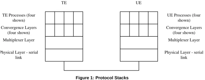
The multiplexer provides mechanisms for conveying streams of data between TE and UE over a single start-stop framed, serial link. Figure 1 shows the arrangement of the various protocol levels and functions. The multiplexer layer provides multiplexing of data arranged in octet streams with no other framing; if the structure of the data has to be conveyed, a convergence layer may be necessary. The present document defines some convergence layers, others may be added later.
Physical Layer - serial link Multiplexer Layer Convergence Layers (four shown) UE Processes (four shown)
Physical Layer - serial link Multiplexer Layer Convergence Layers (four shown) TE Processes (four shown) TE UE
Figure 1: Protocol Stacks
The multiplexer provides a virtual connection between a process in the TE and a similar process in the UE. For example, a PC application supporting SMS functions could be connected to the SMS handler in the UE via a multiplexer channel.
The present document uses start-stop transmission with eight-bit characters. Communication between the two multiplexing entities takes place using frames constructed as defined below.
Each channel between TE and UE is called a Data Link Connection (DLC) and is established separately and sequentially.
Each DLC may have individual flow control procedures for buffer management purposes and the aggregate link also has overall flow control mechanisms.
DLCs have two modes of operation; Error-Recovery Mode (ERM) and non-error-recovery mode (non-ERM), the choice of mode is made when a DLC is established. DLCs using error recovery mode may exist on the same link as DLCs using non-error recovery mode. If the error-recovery mode (ERM) is to be used at least on one DLC, then the multiplexer must be configured with the ISO HDLC transparency mechanism. The use of error recovery mode is optional. Non-error recovery mode uses the UI frame or UIH frame to carry user data; error recovery mode uses the I frame.
The multiplexer has three operating options, basic, advanced without error recovery and advanced with error recovery. The characteristics of the options are:
Basic:
- length indicator used instead of the HDLC transparency mechanism; - different flag octet from that used by HDLC;
- can not be used on links which use XON/XOFF flow control; - may have longer recovery procedure from loss of synchronisation. Advanced without error recovery:
- asynchronous HDLC procedures in accordance with ISO/IEC 13239; - can be used on links which use XON/XOFF flow control;
- recovers quickly from loss of synchronisation. Advanced with error recovery:
- Uses HDLC error-recovery procedures.
5
Non Error Recovery mode Options
This clause describes the non-error-recovery options (basic and advanced) of the multiplexer. The main are given below:
- a simple set of procedures with no error recovery mechanism, for use on reliable connections; - data transparency is provided by the HDLC mechanism (advanced option only);
- a multiplexer control channel which conveys management and control information between the UE and TE; - a mechanism that permits either UE or TE to enter power-saving modes without compromising the integrity of
the multiplexer;
- a comprehensive set of convergence layers which enables many types of data to be carried while preserving the structure of the original data.
The use of the transparency mechanism must be set up at the beginning of the multiplexing session. It is a characteristic for the entire multiplexing session.
The simple set of procedures uses UIH frames to transmit information; these frames are easy to process because their structure permits the HDLC Frame Check Sequence (FCS) to be pre-calculated rather than being constructed on a character-by character basis. The procedures used are very straightforward and it is not necessary to implement the usual HDLC state machines.
UI frames or UIH frames may be used for those channels where the timely delivery of the information is more
important than its reliability because erroneous frames will be discarded. UI frames would be used in those cases where it is important that the data delivered is accurate.
5.1
Service Interface Definition
This clause describes the services provided by the 3GPP TS 27.010 data link layer to the upper layer. The interface is specified in terms of primitives and parameters.
NOTE: This clause is only for information, detailed description of the parameters is found in the following clauses.
5.1.1
Service Definition Model
The present document is intended to define a protocol that can be used to emulate a serial port. In most systems the 27.010 will be a part of a port driver which includes a port emulation entity that must support existing communication APIs. The communication APIs vary from operating system to operating system and from device to device. The present document does not specify how 27.010 is used by a port driver to emulate an existing API but instead focus on a set of services that can be used by all port drivers. Port drivers are not required to use all the services of 27.010.
Legacy Application Legacy Application
Port Emulation Entity Port Emulation Entity Write Read 07.10 07.10 Control Write Read Request Confirm Control Parameters Parameter Setting Response Indication Control Port interface e.g. VCOMM Control Parameters Parameter Setting 07.10 service IF Driver
The legacy application utilises a conventional serial port communication interface. The port emulation entity maps a system specific communication interface to 27.010 services. The 27.010 provides several transparent data stream channels and a control channel. The port interface is the application programmers interface for communication. It varies from system to system and one example is Virtual comm ports in windows.
5.1.2
Start up services
These services are used to start the TS 27.010 multiplexer operation over a serial channel. The following services are provided:
TS0710_START.request (mode, system_parameters); TS0710_START.indication (mode, system_parameters); TS0710_START.response (mode, system_parameters, accept); TS0710_START.confirm (mode, system_parameters, accept).
Description: the request primitive is used to request that the multiplexer mode to be turned on in the desired mode and
system parameters. The indication primitive transfers the request to start multiplexer operation along with the desired mode and system parameters to the upper layer of the target device. If the target device accepts the request by issuing an affirmative response primitive, the suggested mode and system parameters will become valid. The confirm primitive is returned to the upper layer of the requesting device. A successful establishment of the multiplexer mode is indicated by the accept parameter being set to “true”. If the accept parameter is set to “false” the returned values for the other parameters are those suggested by the responding device.
Parameters:
mode = [Basic | HDLC - UIH frames | HDLC - UI frames | HDLC - frames]. (Note that the frame type for HDLC
system_parameters = Port speed [9,6 | 19,2 | 38,4 | 57,6 | 115,2 |
230,4 kBit/s],
Maximum Frame Size [1 – 128 in Basic mode, 1 – 512 in HDLC modes
default: 31 for the basic option and 64 for the advanced option]
Acknowledgement Timer [0,01s-2,55s, default: 0,1s]
Maximum number of retransmissions [0 – 100, default : 3]
Response timer for the multiplexer control channel [0,01s-2,55s, default: 0,3s]
Wake up response timer [1s – 255s, default 10s] Window size for error recovery mode [1 – 7,
default : 2]
accept = [true | false]
Support of the mode parameter is optional. If the mode parameter is omitted, Basic mode is implied. Note that some of the above system parameters can be redefined for the individual DLCs, se below under DLC establishment services.
5.1.3
DLC establishment services
The DLC establishment services are used to open DLC’s on the multiplexer channel. The following services are provided:
TS_0710_DLC_ESTABLISHMENT.request(DLCI, system_parameters); TS_0710_DLC_ESTABLISHMENT.indication(DLCI, system_parameters); TS_0710_DLC_ESTABLISHMENT.response(DLCI, system_parameters, accept); TS_0710_DLC_ESTABLISHMENT.confirm(DLCI, system_parameters, accept).
Description: The transmitting device uses the request primitive initiate the establishment of a new DLC with a desired
set of system parameters on the multiplexer channel. The indication primitive is passed to the upper layer by the TS 27.010 layer of the receiving device on reception of the DLC establishment request. The receiving device uses the
response primitive to either accept or reject the proposed DLCI with its system parameters. On rejection, it is possible
to suggest a modified set of system parameters. The confirm primitive is passed to the upper layer of the transmitting device on reception of the response from the receiving device.
Parameters:
DLCI = 1-63 (DLCI number)
System parameters = Type of frame [UIH | UI | I, default: UIH],
Convergence layer [1 - 4, default: 1] Priority [0-63]
Acknowledgement Timer [0,01s-2,55s, default: 0,1s]
Maximum Frame Size [1 – 32768, default: 31 for the basic option and 64 for the advanced option]
Maximum number of retransmissions [0 – 255, default : 3]
Window size for error recovery mode [1 – 7, default : 2]
Accept = [true | false]
5.1.4
Data services
The data services provided are:
TS_0710_DATA.request(DLCI, User_data); TS_0710_DATA.indication(DLCI, User_data).
Description: the transmitting unit initiates transmission of data using the frame type specified for the chosen DLCI by
means of the request primitive. The transmitted data is delivered to the upper layer of the receiving by the indication primitive. No confirmation primitive exists even for the error recovery mode. In this mode TS 27.010 will take care of all mechanisms involved in the error checking and thus deliver data error free.
Parameters:
DLCI = [1 – 63] DLC over which the data is to be transmitted. User_data= Data to be transferred organised in accordance with the
convergence layer of the DLC
5.1.5
Power Control services
In some application it might be desirable for either the DTE or the DCE to enter a power saving mode with a minimum of communication activities taking place. Services that support this functionality are the Sleep services and the Wakeup services.
5.1.5.1
Sleep services
TS_0710_SLEEP.request; TS_0710_SLEEP.indication; TS_0710_SLEEP.confirm.Description: the request primitive is used to advice the receiving device that the transmitter wishes to enter a low
power state. The TS 27.010 layer of the receiving unit sends an indication primitive to the upper layer in order to inform that the transmitting unit has entered the power saving state. The TS 27.010 layer will automatically transmit an
acknowledge message to the transmitting device, thus no response primitive is required. The confirm primitive is sent to the upper layer of the transmitting device when the low power request has been received, and indicates that the
TS 27.010 layer has entered the low power mode. Note that the Receiving device is not required to enter a low power mode, but it will be considered to have done so by the TS 27.010 layer.
5.1.5.2
Wakeup services
TS_0710_WAKEUP.indication; TS_0710_WAKEUP.response.Description: the indication primitive is sent to the upper layer when the TS 27.010 layer of the receiving unit receives a
request to wake up from the power saving state. When the receiving device is ready to resume operation on the multiplexer channel this is indicated to the TS 27.010 layer in the receiving unit by means of the response primitive. Sins the wakeup routine is initiated by the transmitting device attempting to communicate, neither request nor confirm primitives are provided for the wakeup service. The transmitting device instead uses the Data services described below.
5.1.6
DLC Release services
The DLC release services are used to disconnect a DLC. The following services are provided: TS_0710_DLC_RELEASE.request(DLCI);
Description: The request primitive is used by the upper layer in the transmitting device to initiate close down of the
selected DLC in TS 27.010. The TS 27.010 layer of the receiving device uses the indication primitive to inform the upper layer that the DLC has been closed down.
Parameters:
DLCI = [1 – 63] Number of the DLC to be released.
5.1.7
Close down services
The Close down services are used to terminate multiplexer operation on the serial channel and resume AT mode. The services provided are:
TS_0710_CLOSE.request; TS_0710_CLOSE.indication.
Description: when the request primitive is passed to the TS 27.010 layer of the transmitting device close down of the
multiplexer mode is initiated and a close down command is sent to the receiving device. On reception of the close down command the TS 27.010 layer of the receiving device sends the indication primitive to the upper layer and the
multiplexer mode is terminated.
5.1.8
Control Services
5.1.8.1
27.010 Services
5.1.8.1.1
DLC parameter negotiation
These services are used to negotiate and set parameters for a specific DLC. The following services are provided: TS0710_PARNEG.request (DLC, DLC parameters);
TS0710_PARNEG.indication (DLC, DLC_parameters); TS0710_PARNEG.response (DLC, DLC_parameters, accept); TS0710_PARNEG.confirm (DLC, DLC_parameters, accept).
Description: the request primitive is used to request that the remote 27.010 entity changes a specific DLC connection
parameters. An indication is sent to the remote port emulation entity. The remote emulation entity replies with a response witch is forwarded as an confirmation to the originating port emulating entity.
DLC_parameters = frame type [ UIH | UI | I ,
default: UIH ]
Convergence Layer Type [ Type 1 | Type 2 | Type 3 | Type 4, default: Type 1]
Priority [1-63,
default: according to table in clause 5.6] Acknowledgement timer [10 ms - 25.5 sec,
deault: 100 ms]
Maximum Frame Size [1 – 32768, default: 31 for the basic option and 64 for the advanced option]
Maximum number of retransmissions [0 – 100, default : 3]
Response timer for the multiplexor control channel [0,01s-2,55s, default: 0,3s]
Wake up response timer [1s – 255s, default 10s] Window size for error recovery mode [1 – 7,
default : 2]
5.1.8.1.2
DLC Service Negotiation service
These services are used to negotiate and set a specific service on a DLC. The following services are provided: TS0710_SERVNEG.request (DLC, Service_parameters);
TS0710_SERVNEG.indication (DLC, Service_parameters); TS0710_SERVNEG.response (DLC, Service parameters, accept); TS0710_SERVNEG.confirm (DLC, Service_parameters, accept).
Description: the request primitive is used to request a specific service on a DLC. The indication is sent to the other port
emulation. The remote port emulation entity replies with a response containing accepted or possible services. The originating port emulation entity receives a confirm on the request with either an accept or a possible service list.
service_parameters = Service [ data | voice 64kbit/s A-law PCM | reserved 1 | reserved 2 ],
voice codec [ 3GPP TS 46.021 | 64kbit/s u-law PCM | coded ADPCM 32kbit/s | coded half rate | 128 kbit/s PCM | reserved ]
5.1.8.1.3
Test service
These services are used to test the communication link between two 27.010 entities. The following services are provided:
TS0710_TEST.request (Test data); TS0710_TEST.confirm (Test data).
Description: the request primitive is used to request a test of the communication link. The data is sent to the remote
entity, which loops it back. The confirmation is sent to the originating port emulation entity containing the looped data.
Test Data = Data to be transferred as a test pattern, organised in accordance with the
convergence layer of the 27.010 control channel.
5.1.8.1.4
Flow control services
The flow control services provided are: TS_0710_FLOW.request(DLCI,State); TS_0710_FLOW.indication(DLCI, State).
Description:
The request primitive with State = disable disables the issuing of TS_0710_DATA.indications by the 27.010 entity. The request primitive with State = enable enables the issuing of TS_0710_DATA.indications by the 27.010 entity. These requests may or may not result in the remote 27.010 entity issuing a TS_0710_FLOW.indication to the remote service user, depending on the states of the buffers in the 27.010 entities.
The indication primitive with State = disable disables the issuing of TS_0710_DATA.requests by the service user. The indication primitive with State = enable enables the issuing of TS_0710_DATA.requests by the service user. These indications may or may not have resulted from the receipt by the remote 27.010 entity of a TS_0710_FLOW.request from the remote service user. They may have been issued by the local 27.010 entity as a result of its buffer state. The initial state of the 27.010 entity is with data flow enabled.
Parameters:
DLCI = [1 – 63] DLC over which the data is to be transmitted.
5.1.8.2
Port Emulation Services
5.1.8.2.1
Remote DLC parameter negotiation service
These services are used to negotiate and set of parameters for a remote communication port. The following services are provided:
TS0710_PORTNEG.request (DLC, Port_parameters); TS0710_PORTNEG.indication (DLC, Port_parameters); TS0710_PORTNEG.response (DLC, Port parameters, accept); TS0710_PORTNEG.confirm (DLC, Port_parameters, accept).
Description: The request primitive is used to request that the remote port changes its parameters. The indication is sent
to the other port emulation entity. The remote port emulation entity replies with a response. A confirm is sent to the originating port entity.
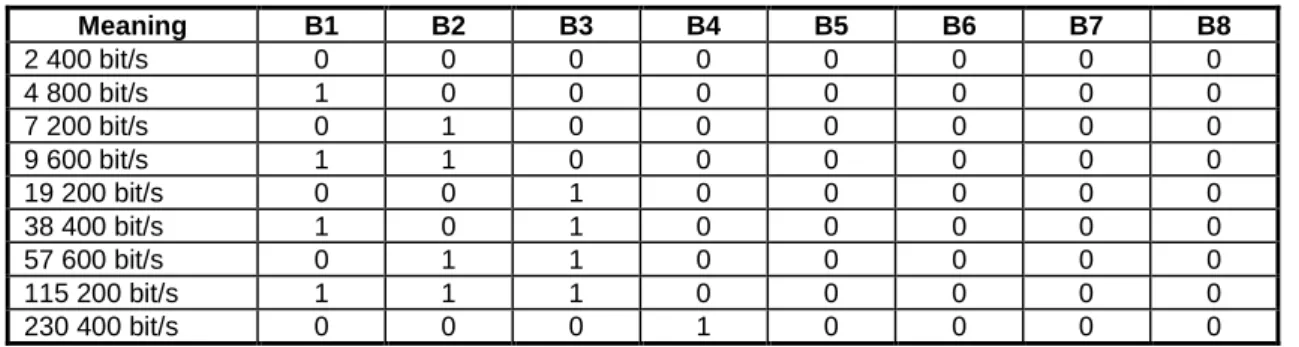
port_parameters = Port speed [2,4 | 4,8 | 7,2 | 9,6 | 19,2 | 38,4 | 57,6 | 115,2 |
230,4 kBit/s],
Data bits [ 5 | 6 | 7 | 8,
default: 8 bits | Stop bits [ 1 | 1,5, default: 1 bit |
Parity [ no parity | parity, default: no parity |
Parity Type [ odd | even | mark | space]
accept = [true | false]
5.1.8.2.2
DLC Control Parameter service
The DLC Control Parameter service is used to convey control parameters between Port Emulation Entities. Default values should be assumed if no control parameter has been designated since the DLC has been made. This service is to control a specific DLC. It includes such as flow control, Modem signals, Break. The following services are provided:
TS0710_CONTROL.request (DLC, Control_parameters); TS0710_CONTROL.indication (DLC, Contol_parameters); TS0710_CONTROL.response (DLC, Contro_parameters); TS0710_CONTROL.confirm (DLC, Control_parameters).
Description: the request primitive is used to convey control information to the remote port. The indication is sent to the
other port emulation entity. The remote port emulation entity replies with a response which is sent to the originating 27.010 entity. A confirm is sent back to the port emulation entity.
system_parameters = Modem Signal [DTR/DSR | RTS/CTS | RI | DCD ],
Break Signal [0—3 s in steps of 200 ms, default 0ms ],
Buffers [do not discard buffers, discard buffer default: do not discard buffers],
Break signal sequence [ as soon as possible | in sequence, default: in sequence]
5.1.8.2.3
DLC Line status indication service
These services are used to indicate a DLC line status to a remote port emulation entity.. The following services are provided:
TS0710_PORTNEG.request (DLC, Line Status parameter); TS0710_PORTNEG.indication (DLC, Line Status parameter).
Description: the request primitive is used to send the line status to the remote device. The indication is sent to the other
port emulation entity. The remote port emulation does not reply.
Line status parameter = Port speed [no errors, overrun error, parity error, framing error]
5.2
Frame Structure
All information transmitted between the TE and UE is conveyed in frames.
5.2.1
Frame Fields
The frame structure is composed of an opening and a closing flag, an Address field, a Control field, an Information field and FCS field. A length indication field is present in each frame if no transparency mechanism is used for the
multiplexing session.
5.2.1.1
Flag Sequence Field
Each frame begins and ends with a flag sequence octet which is defined as a constant bit pattern.
5.2.1.2
Address Field
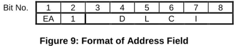
The address field consists of a single octet. It contains the Data Link Connection Identifier (DLCI), the C/R bit and the address field extension bit as shown in figure 2.
Bit No. 1 2 3 4 5 6 7 8
EA C/R D L C I
Figure 2: Format of Address Field
The DLCI is used to identify an individual user information stream as well as to identify connections between TE and UE. Multiple DLCIs shall be supported but the number is implementation-specific. The DLCIs are dynamically assigned. The values used for specific DLCIs are given in clause 5.6.
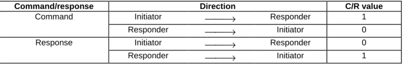
The C/R (command/response) bit identifies the frame as either a command or a response. In conformance with HDLC rules, a command frame contains the address of the data link connection entity to which it is transmitted while a response frame contains the address of the data link connection entity transmitting the frame. For a given DLC, the DLCI value of the address field remains the same but the C/R bit changes, as shown in table 1.
Table 1: Command/response bit usage
Command/response Direction C/R value
Command Initiator
→
Responder 1Responder
→
Initiator 0Response Initiator
→
Responder 0Responder
→
Initiator 1Initiator is the station that take the initiative to initialize the multiplexer (i.e. sends the SABM command at DLCI 0 ) and the responder is the station that accepts the initialization of the multiplexer (i.e. sends the UA response at DLCI 0) See clause 5.4.3.1 for more details about C/R bit.
According to the rules of ISO/IEC 13239, the range of the address field may be extended by use of the EA bit. When the EA bit is set to 1 in an octet, it signifies that this octet is the last octet of the address field. When the EA bit is set to 0, it signifies that another octet of the address field follows. In the present document there is only one address octet so the EA bit is always set to 1. Note that future amendments to the present document may extend the address field and use the EA bit.
5.2.1.3
Control Field
The content of the control field defines the type of frame. The control fields of the frames used in the present document are described in table 2.
Table 2: Coding of Control Field
Frame Type 1 2 3 4 5 6 7 8 Notes
SABM (Set Asynchronous Balanced Mode) 1 1 1 1 P/F 1 0 0 UA (Unnumbered Acknowledgement) 1 1 0 0 P/F 1 1 0 DM (Disconnected Mode) 1 1 1 1 P/F 0 0 0 DISC (Disconnect) 1 1 0 0 P/F 0 1 0
UIH (Unnumbered Information with Header check)
1 1 1 1 P/F 1 1 1
UI (Unnumbered Information) 1 1 0 0 P/F 0 0 0 Optional
In table 2, P/F is the Poll/Final bit. The functions of these bits are described later.
5.2.1.4
Information Field
The information field is the payload of the frame and carries the user data and any convergence layer information. The field is octet structured. The information field is only present in I frames, UI frames and UIH frames.
5.2.1.5
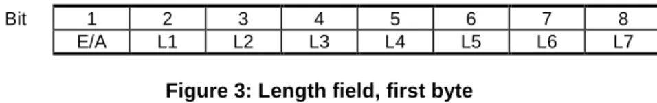
Length Indicator
This field is present only in case when basic option is activated. It has the following format:
Bit 1 2 3 4 5 6 7 8
E/A L1 L2 L3 L4 L5 L6 L7
Figure 3: Length field, first byte
The L1 to L7 bits indicates the length of the following data field. The default length is 31 bytes.
According to the rule of ISO/IEC 13239, the range of the length field may be extended by use of the EA bit. When the EA bit is set to 1 in an octet, it is signifies that this octet is the last octet of the length field. When the EA bit is set to 0, it signifies that a second octet of the length field follows. The total length of the length field is in that case 15bits, L1-L15.
The second octet of the length field (only present when the EA field in the first byte is set to 0) format:
Bit 1 2 3 4 5 6 7 8
L8 L9 L10 L11 L12 L13 L14 L15
Figure 4: Length field, second byte
5.2.1.6
Frame Checking Sequence Field (FCS)
The FCS shall be the ones complement of the sum (modulo 2) of:a) the remainder of
xk(x7+ x6+ x5+ x4+ x3+ x2+ x1+ 1)
divided (modulo 2) by the generator polynomial
x8+ x2+ x + 1,
where k is the number of bits in the frame existing between, but not including, the final bit of the opening flag and the first bit of the FCS, excluding start and stop elements (start/stop transmission), and bits (synchronous transmission) and octets (start/stop transmission) inserted for transparency, and
b) the remainder of the division (modulo 2) by the generator polynomial
x8+ x2+ x + 1
of the product of x8by the content of the frame existing between, but not including, the final bit of the opening flag and the first bit of the FCS, excluding start and stop elements (start/stop transmission), and bits (synchronous transmission) and octets (start/stop transmission) inserted for transparency.
As a typical implementation, at the transmitter, the initial content of the register of the device computing the remainder of the division is preset to all ones and is then modified by division by the generator polynomial (as described above) of the address, control and information fields; the ones complement of the resulting remainder is transmitted as the 8-bit FCS.
At the receiver, the initial content of the register of the device computing the remainder is preset to all ones. The final remainder after multiplication by x8and then division (modulo 2) by the generator polynomial
x8+ x2+ x + 1
of the serial incoming protected bits and the FCS, will be 1111 0011 (x7through x0, respectively) in the absence of
transmission errors.
In the case of the UIH frame, the contents of the I-field shall not be included in the FCS calculation. FCS is calculated on the contents of the address, control and length fields only. This means that only the delivery to the correct DLCI is protected, but not the information. The FCS is calculated in the normal manner for all other frames in Table 2.
5.2.2
Format Conventions
All transmitted characters will be sent using one start bit, eight data bits, no parity bit and one stop bit. In the field descriptions, bit 1 is transmitted first.
Addresses, commands, responses and sequence numbers shall be transmitted low-order bit first (for example, the first bit of the sequence number that is transmitted shall have the weight 20).
The FCS shall be transmitted to the line commencing with the coefficient of the highest term.
NOTE: The use of these conventions in the present document means that octet values are often expressed in the reverse bit order from conventions used in many other standards. The conventions are used here because of the importance of the correct order of bit transmission; care should be taken during implementation.
5.2.3
Frame Validity
An invalid frame in the frame format is one which meets any one (or more) of the following conditions: - is not properly bounded by two flags;
- does not have at least three octets between flags after removal of characters inserted for transparency; - indicates presence of a transmission error in that the FCS check fails;
- contains an address field with more than one octet.
Invalid frames shall be discarded without notification to the sender. Actions taken by the multiplexer to indicate reception of an invalid frame to the UE or TE are left to implementers. However, an indication that a frame with an FCS error has been received may be of use when supporting DLCs for voice/audio.
As an optional procedure in response to an invalid frame in error recovery mode, a receiver may transmit an REJ frame.
5.2.4
Frame Abort
Aborting a frame is not supported.
5.2.5
Inter-frame Fill
The time between frames shall be filled by sending continuous stop-polarity except in the case of the wake-up procedure (see clause 5.4.7). The receiver shall also operate correctly if the time between frames is filled with flag characters. If a receiver receives more than three consecutive flags it shall begin to transmit continuous flags at the first available time (see clause 5.4.7).
5.2.6
Basic Option
In this case, opening flag and closing flags may appear in the Information field of the frame. The flags cannot be used to determine beginning and end of a frame. A length indication for the frame must be given instead. The frame structure is then as follows:
Flag Address Control Length Indicator Information FCS Flag 1 octet 1 octet 1 octet 1or2 octets Unspecified length but
integral number of octets
1 octet 1 octet
Figure 5: Frame Structure for Basic option
The flag field in basic option has the following format.
Bit 1 2 3 4 5 6 7 8
1 0 0 1 1 1 1 1
Figure 6: Flag field in basic option
5.2.6.1
Constraint
The closing flag may also be the opening flag of the following frame.
The flag value is different from the one used when the advanced option is activated.
5.2.7
Advanced Option
If the advanced option is activated at the beginning of the multiplexing session, then it is used for all frames. This mechanism is based on a control octet transparency. It is based on a unique appearance of the opening and the closing flag in each frame. These flags will never appear in the information field of the frame. This mechanism allows a very quick synchronisation if a loss of synchronisation has occurred on the TE-UE link.
5.2.7.1
Control-octet transparency
The following transparency mechanism shall be applied to each frame from address field to FCS field inclusive. The control escape octet is a transparency identifier that identifies an octet occurring within a frame to which the following transparency procedure is applied. The encoding of the control escape octet is:
1 2 3 4 5 6 7 8 Bit position in octet 1 0 1 1 1 1 1 0
Low order bit, first bit transmitted/received
The transmitter shall examine the frame between the opening and closing flag sequences including the address, control, and FCS fields and, following completion of the FCS calculation, shall:
- Upon the occurrence of the flag or a control escape octet, complement the 6th bit of the octet; and
- Insert a control escape octet immediately preceding the octet resulting from the above prior to transmission. The receiver shall examine the frame between the two flag octets and shall, upon receipt of a control escape octet and prior to FCS calculation:
- Discard the control escape octet; and
- Restore the immediately following octet by complementing its 6th bit.
Other octet values may optionally be included in the transparency procedure by the transmitter. Such inclusion shall be subject to prior system/application agreement.
5.2.7.2
Start/stop transmission - extended transparency
The transmitter may apply the above transparency procedure to other octets in addition to the flag and control escape octets. At present, the only other octets are flow-control characters. The procedure is described in clause 5.2.6.3.
5.2.7.3
Flow-control transparency
The flow-control transparency option provides transparency processing for the DC1/XON and DC3/XOFF control characters defined in ISO/IEC 646 (i.e., 1000100x and 1100100x, respectively, where x may be either 0 or 1). This has the effect of assuring that the octet stream does not contain values which could be interpreted by intermediate
equipment as flow control characters (regardless of parity).
5.2.7.4
Frame Structure
The frame structure is shown in figure 7. Note that this structure does not include information added for synchronisation (i.e. Start and stop bits) or transparency purposes. The order of transmission is from left to right.
In case the Transparency mechanism is activated, the frame structure is as follows.
Flag Address Control Information FCS Flag
1 octet 1 octet 1 octet Unspecified length but integral number
of octets
1 octet 1 octet
Figure 7: Frame Structure for Advanced option
The flag field in advanced option has the following format.
Bit 1 2 3 4 5 6 7 8
0 1 1 1 1 1 1 0
Figure 8: Flag field in advanced option
NOTE: The closing flag may also be the opening flag of the following frame.
5.3
Frame Types
5.3.1
Set Asynchronous Balanced Mode (SABM) command
The SABM command shall be used to place the addressed station in the Asynchronous Balanced Mode (ABM) where all control fields shall be one octet in length. The station shall confirm acceptance of the SABM command by
transmission of a UA response at the first opportunity. Upon acceptance of this command, the DLC send and receive state variables shall be set to zero.
5.3.2
Unnumbered Acknowledgement (UA) response
The UA response shall be used by the station to acknowledge the receipt and acceptance of SABM and DISC commands.
5.3.3
Disconnected Mode (DM) response
The DM response shall be used to report a status where the station is logically disconnected from the data link. When in disconnected mode no commands are accepted until the disconnected mode is terminated by the receipt of a SABM command. If a DISC command is received while in disconnected mode a DM response should be sent.
5.3.4
Disconnect (DISC) command
The DISC command shall be used to terminate an operational or initialization mode previously set by a command. It shall be used to inform one station that the other station is suspending operation and that the station should assume a logically disconnected mode. Prior to actioning the command, the receiving station shall confirm the acceptance of the DISC command by the transmission of a UA response.
DISC command sent at DLCI 0 have the same meaning as the Multiplexer Close Down command (see clause 5.4.6.3.3). See also clause 5.8.2 for more information about the Close-down procedure.
5.3.5
Unnumbered information with header check (UIH) command and
response
The UIH command/response shall be used to send information without affecting the V(S) or V(R) variables at either station. UIH is used where the integrity of the information being transferred is of lesser importance than its delivery to the correct DLCI. For the UIH frame, the FCS shall be calculated over only the address, control and length fields.
Reception of the UIH command/response is not sequence number verified by the data link procedures; therefore, the UIH frame may be lost if a data link exception occurs during transmission of the protected portion of the command, or duplicated if an exception condition occurs during any reply to the command. There is no specified response to the UIH command/response.
5.3.6
Unnumbered Information (UI) command and response
The UI command/response shall be used to send information without affecting the V(S) or V(R) variables at either station. Reception of the UI command/response is not sequence number verified by the data link procedures; therefore, the UI frame may be lost if a data link exception occurs during transmission of the protected portion of the command, or duplicated if an exception condition occurs during any reply to the command. There is no specified response to the UI command/response.
For the UI frame, the FCS shall be calculated over all fields (Address, Control, Length Indicator, Information). Support of UI frames is optional.
5.4
Procedures and States
5.4.1
DLC Establishment
In most cases the establishment of a DLC will be initiated by the TE, however, the protocol is balanced and the initiation may come from the UE. The action taken by the higher layers of the TE upon the initiation of the establishment of a DLC from the UE is outside the scope of the present document.
The station wishing to establish a DLC transmits a SABM frame with the P-bit set to 1. The address field contains the DLCI value associated with the desired connection. If the responding station is ready to establish the connection it will reply with a UA frame with the F-bit set to 1. If the responding station is not ready or unwilling to establish the particular DLC it will reply with a DM frame with the F-bit set to 1.
Once a DLC has been established the stations are both said to be in a connected mode, for the particular DLC, and transfer of information may commence.
If no UA or DM response has been received after T1 the initiating station may retransmit the SABM. This action may be repeated until a response is obtained or action is taken by a higher layer.
If no negotiation procedure is used, DLC parameters are the default one.
5.4.2
DLC Release
The release of a DLC may be initiated by either station by the transmission of a DISC frame with the P-bit set to one. Confirmation of the DLC release is signalled by the other station sending a UA frame with the F-bit set to 1. Once the DLC has been released the stations enter disconnected mode for that particular DLC.
If the station receiving the DISC command is already in a disconnected mode it will send a DM response.
If no UA or DM response has been received after T1 the initiating station may retransmit the DISC. This action may be repeated until a response is obtained or action is taken by a higher layer.
5.4.3
Information Transfer
5.4.3.1
Information Data
Information is conveyed using UI or UIH frames. Support of UIH frames is mandatory and support of UI frames is optional. UI frames are used when it is important to know that data received is correct. An example of the use of UI frames is in carrying IP (Internet Protocol) traffic where error recovery procedures are performed, if necessary, by a higher layer. The use of UIH frames is appropriate if the link is not subject to errors. UI or UIH frames may also be used for data in situations where the delays inherent in error-recovery procedures are unacceptable, such as transmission of voice data.
The transmitter takes information from the convergence layer for the particular DLC and places it in the I-field of the transmitted frame. Once a UI or UIH frame has been correctly received, the contents of its I-field is passed to the convergence layer.
The frames sent by the initiating station have the C/R bit set to 1 and those sent by the responding station have the C/R bit set to 0. Both stations set the P-bit to 0.
See clause 5.2.1.2 for more details about C/R bit.
The maximum length of the information field in UI or UIH frames shall be parameter N1 (see clause 5.7.2).
5.4.3.2
Priority
Each data stream has a priority associated with it. The priority is a number in the range 0-63 with lower numbers having higher priority. The TE assigns a priority to each DLC and informs the UE of the priority by means of the multiplexer control channel (see clause 5.4.6.3.1). In the absence of a message assigning priorities DLCs shall be given the priority according to the DLCI Assignment table in clause 5.6. The transmitter is in control of which frames are transmitted and how they are constructed and it is not intended to specify precisely how this task is performed. If data of higher priority than that currently being transmitted is waiting the transmitter has several options available:
a) complete the transmission of the current frame; or
b) terminate the assembly of the current frame by sending the current FCS and terminating flag (only for Advanced option);
and start sending the frame of higher-priority data.
Handling of DLC with equal priorities should not favour one over the others. The DLC with the highest priority shall not block any of the lower priorities DLC. Interleaving of higher priority and lower priority frames is necessary in order to avoid permanent blocking of lower priority channels. Optimization of this interleaving for a specific implementation may have a significant impact on the application in use and therefore implementers are encouraged to consider this carefully.
5.4.4
Frame Variables
The poll (P) bit set to 1 shall be used by a station to solicit (poll) a response or sequence of responses from the other station.
The final (F) bit set to 1 shall be used by a station to indicate the response frame transmitted as the result of a soliciting (poll) command.
The poll/final (P/F) bit shall serve a function in both command frames and response frames. (In command frames, the P/F bit is referred to as the P bit. In response frames, it is referred to as the F bit).
5.4.4.1
Functions of the poll bit
The P bit set to 1 shall be used to solicit a response frame with the F bit set to 1 from the other station at the earliest opportunity.
On a particular DLCI, only one frame with a P bit set to 1 shall be outstanding in a given direction at a given time. In the case where a SABM or DISC command with the P bit set to 0 is received then the received frame shall be discarded.
If a unsolicited DM response is received then the frame shall be processed irrespective of the P/F setting.
Before a station issues another frame with the P bit set to 1, it shall have received a response frame from the other station with the F bit set to 1. If no valid response frame is obtained within a system-defined time-out period, the retransmission of a command with the P bit set to 1 for error recovery purposes shall be permitted.
5.4.4.2
Functions of the final bit
A response frame with the F bit set to 1 shall be used by a station to acknowledge the receipt of a command frame with the P bit set to 1. The response shall be made at the earliest opportunity.
The station may transmit response frames with the F bit set to 0 at any opportunity on an asynchronous basis. However, in the case where a UA response is received with the F bit set to 0 then the received frame shall be discarded.
If an unsolicited DM response is received then the frame shall be processed irrespective of the P/F setting. If a station receives a command with the P bit set to 1, transmission of a response with the F bit set to 1 shall take precedence over transmission of other commands, with the exception of the mode setting commands (SABM or DISC).
5.4.5
Time-out considerations
In order to detect a no-reply or lost-reply condition, each station shall provide a response time-out function (T1). The expiry of the time-out function shall be used to initiate appropriate error recovery procedures.
The duration of the time-out function in the two stations shall be unequal in order to resolve contention situations. The time-out function shall be started whenever a station has transmitted a frame for which a reply is required. When the expected reply is received, the time-out function shall be stopped. If, during the interval that the time-out function is running, other frames are sent for which acknowledgements are required, the time-out function may have to be
restarted.
If the response time-out function runs out, a command with the P bit set to 1 may be (re)transmitted, and the response time-out function restarted.
5.4.6
Multiplexer Control Channel
At the initiation of communication between the TE and UE a control channel is set up with DLCI 0 using the procedures of clause 5.8.1. This channel is used to convey information between the two multiplexers. The control channel may use either error recovery mode or non-error recovery mode procedures as defined by the +CMUX command (3GPP TS 27.007 [4]). If error recovery mode procedures are available they should be used.
5.4.6.1
Message format
All messages sent between the multiplexers conform to the following type, length, value format:
Type Length Value 1 Value2 … Value n
Each box in the diagram represents a field of minimum size one octet. The type and length octets have extension bits so those fields may contain more than one octet.
The first type field octet has the following format:
Bit 1 2 3 4 5 6 7 8
EA C/R T1 T2 T3 T4 T5 T6
Subsequent type field octets have the following format:
Bit 1 2 3 4 5 6 7 8
EA T7 T8 T9 T10 T11 T12 T13
The EA bit is an extension bit. The EA bit is set to 1 in the last octet of the sequence; in other octets EA is set to 0. If only one octet is transmitted EA is set to 1.
The T bits indicate the type coding. Each command has a unique pattern of bits. This means that a single-octet type field can encode 63 different message types. Only single octet message types are defined in the present document.
The first length field octet has the following structure:
Bit 1 2 3 4 5 6 7 8
EA L1 L2 L3 L4 L5 L6 L7
Subsequent length field octets have the same structure.
The EA bit is an extension bit. The EA bit is set to 1 in the last octet of the sequence; in other octets EA is set to 0. If only one octet is transmitted EA is set to 1.
The L bits define the number of value octets that follow. In the case of a single-octet length field L1 is the LSB and L7 is the MSB; this permits messages with up to 127 value octets to be constructed.
The contents of the value octets are defined for each message type in clause 5.4.6.3.
Multiple messages may be included in the same frame (as long as the maximum frame size is not exceeded). Messages may not be split over more than one frame.
5.4.6.2
Operating procedures
Messages always exist in pairs; a command message and a corresponding response message. If the C/R bit is set to 1 the message is a command, if it is set to 0 the message is a response. A response message has the same T bits as the
command that provoked it.
If a command does not produce a response within a time T2 the command may be sent again up to N2 times. If no response is received on the N2 transmissions, the multiplexer control channel should be considered faulty and an alarm raised. Resolution of the error situation is implementation dependent.
NOTE: Notice that when UIH frames are used to convey information on DLCI 0 there are at least two different fields that contain a C/R bit, and the bits are set of different form. The C/R bit in the Type field shall be set as it is stated above, while the C/R bit in the Address field (see clause 5.2.1.2) shall be set as it is described in clause 5.4.3.1.
5.4.6.3
Message Type and Actions
5.4.6.3.1
DLC parameter negotiation (PN)
This procedure is optional. If this command is not supported, default values are applied to each DLC.
Before a DLC is set up using the mechanism in clause 5.4.1, the TE and UE must agree on the parameters to be used for that DLC. These parameters are determined by parameter negotiation.
The parameter negotiation uses the following type field octet:
Bit 1 2 3 4 5 6 7 8
EA C/R 0 0 0 0 0 1
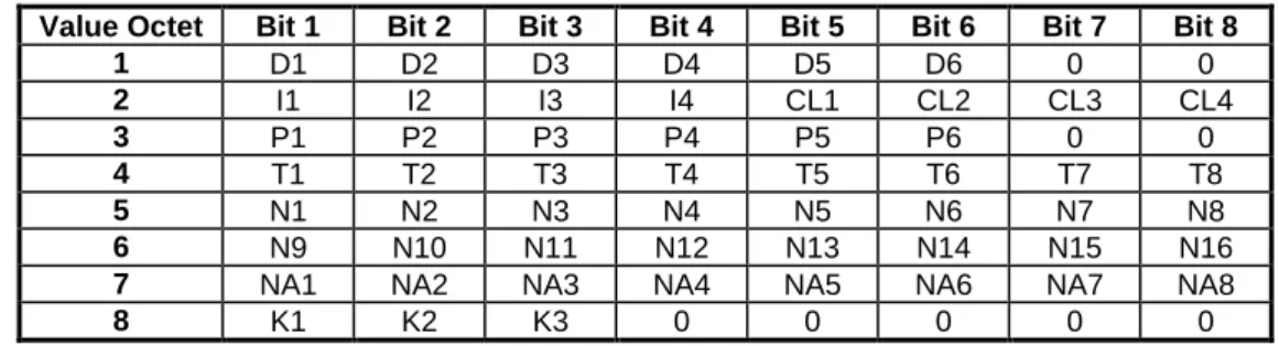
The length field octet contains the value 8 and there follow eight value octets. The value octets contain the information in table 3.
Table 3: Parameter Negotiation
Value Octet Bit 1 Bit 2 Bit 3 Bit 4 Bit 5 Bit 6 Bit 7 Bit 8
1 D1 D2 D3 D4 D5 D6 0 0 2 I1 I2 I3 I4 CL1 CL2 CL3 CL4 3 P1 P2 P3 P4 P5 P6 0 0 4 T1 T2 T3 T4 T5 T6 T7 T8 5 N1 N2 N3 N4 N5 N6 N7 N8 6 N9 N10 N11 N12 N13 N14 N15 N16
7 NA1 NA2 NA3 NA4 NA5 NA6 NA7 NA8
8 K1 K2 K3 0 0 0 0 0
The various fields are coded as follows:
- the D-bits define the DLCI that the other information refers to; Bit D1 is the least significant; - the I-bits define the type of frames used for carrying information in the particular DLC - See table 4.
Table 4: Meaning of I-bits
Meaning I1 I2 I3 I4
Use UIH frames 0 0 0 0
Use UI frames 1 0 0 0
Use I frames (note) 0 1 0 0
NOTE: Refer to clause 6.
Other values are reserved. Default value is 0000.
In the absence of negotiation the frame type used (for DLCI>0) is the same as used by the multiplexer control channel. The CL-bits define the type of convergence layer to be used on the particular DLCI - see table 5.
Table 5: Meaning of CL-bits
Meaning CL1 CL2 CL3 CL4
Type 1 0 0 0 0
Type 2 1 0 0 0
Type 3 0 1 0 0
Type 4 1 1 0 0
Other values are reserved. Default value is 0000.
The P-bits define the priority to be assigned to the particular DLC. The range of values is 0 to 63 with 0 being the lowest priority. P1 is the least significant bit. Default value for P-bits are given by the DLCI values. See clause 5.6. The T-bits define the value of the acknowledgement timer (T1) - see clause 5.7.1. The units are hundredths of a second and T1 is the least significant bit.
The N-bits define the maximum frame size (N1) - see clause 5.7.2. The parameter is a sixteen-bit number with N1 as the least significant bit.
The NA-bits define the maximum number of retransmissions (N2) - see clause 5.7.3. The parameter is an eight-bit number with NA1 as the least significant bit.
The K-bits define the window size for error recovery mode (k) - see clause 5.7.4. The parameter is a three-bit number with K1 as the least significant bit.
The TE transmits a parameter negotiation command to the UE with the fields set to the values that the TE intends to use for the particular DLCI. The UE replies with a parameter negotiation response with its proposed set of values. The following rules must be observed by the UE in constructing its response:
- The DLCI value may not be changed.
- The use of I frames or UI frames is optional so an UE may respond with a UIH choice if it does not implement UI frames or I frames.
- The UE may not change the convergence layer proposed by the TE. - The UE may not change the priority proposed by the TE.
- The T1 value is the one that the TE will use and is not negotiable; the UE will insert its own T1 value. It is advisable that different T1s are used in each direction.
- The UE may propose a smaller value for maximum frame size (N1) if it has insufficient memory to handle the size proposed.
- The N2 value is the one that the TE will use and is not negotiable; the UE will insert its own N2 value. - The UE may propose a smaller value for window size (k) if it has insufficient memory to handle the size
proposed.
If the TE considers the response from the UE to be acceptable the TE will start to establish the DLC in accordance with the procedures of clause 5.3.1. If the response is not acceptable the TE may initiate another parameter negotiation command with revised parameters or pass the failure information to a higher layer.
If an incoming call arrives at the UE from the network for which no DLC has been set up, the UE may initiate the parameter negotiation procedure and set up a DLC. This situation should not occur in practice since a TE will generally set up DLCs for all the functions it shares with the UE after the capabilities exchange. The indication of an incoming call will be through an 07.07 or 07.05 result code.
5.4.6.3.2
Power Saving Control (PSC)
(see also clause 5.4.7).
The power saving control messages use the following type field octet:
Bit 1 2 3 4 5 6 7 8
EA C/R 0 0 0 0 1 0
The length byte contains the value 0 and there are no value octets.
If a station wishes to enter a low-power state it transmits a power saving control command; the other station replies with a power saving control response.
If a station wishes to request that the other station enter a low-power state it sends a power saving control command; the other station replies with a power saving control response. The responding station may enter a low-power state but need not do so.
5.4.6.3.3
Multiplexer close down (CLD)
(see also clause 5.8.2).
The multiplexer close down command is used to reset the link into normal AT command mode without multiplexing. The multiplexer close down messages use the following type field octet:
Bit 1 2 3 4 5 6 7 8
EA C/R 0 0 0 0 1 1
5.4.6.3.4
Test Command (Test)
The test command is used to test the connection between UE and the TE. The length byte describes the number of values bytes, which are used as a verification pattern. The opposite entity shall respond with exactly the same value bytes.
The type field octet has the following format:
Bit 1 2 3 4 5 6 7 8
EA C/R 0 0 0 1 0 0
5.4.6.3.5
Flow Control On Command (FCon)
The flow control command is used to handle the aggregate flow. When either entity is able to receive new information it transmits this command.
The length byte contains the value 0 and there are no value octets. The type field octet has the following format:
Bit 1 2 3 4 5 6 7 8
EA C/R 0 0 0 1 0 1
5.4.6.3.6
Flow Control Off Command (FCoff)
The flow control command is used to handle the aggregate flow. When either entity is not able to receive information it transmits the FCoff command. The opposite entity is not allowed to transmit frames except on the control channel (DLC=0).
The length byte contains the value 0 and there are no value octets. The type field octet has the following format:
Bit 1 2 3 4 5 6 7 8
EA C/R 0 0 0 1 1 0
5.4.6.3.7
Modem Status Command (MSC)
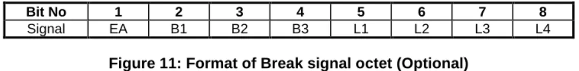
It is desired to convey virtual V.24 control signals to a data stream, this is done by sending the MSC command. The MSC command has one mandatory control signal byte and an optional break signal byte. This command is only relevant when the basic option is chosen.
This command shall be sent prior to any user data after a creation of a DLC.
Command Length DLCI V.24 signals Break Signals
(optional)
The length byte contains the value 2 or 3 and there are 2 or 3 value octets.
Both the DTE and DCE uses this command to notify each other of the status of their own V.24 control signals. The length of the Modem Status Command is either 4 or 5 bytes depending on the break signal.
The command field octet has the following format:
Bit 1 2 3 4 5 6 7 8
EA C/R 0 0 0 1 1 1