Software Architecture of GG1—A Mobile Phone Based
Multimedia Remote Monitoring System
Y. S. Moon W. S. Wong H. C. Ho
Kenneth Wong
Dept of Computer Science & Engineering Dept of Engineering
Chinese University of Hong Kong
Cambridge University
Shatin, HONG KONG
England, U.K.
Abstract
GG1 is a mobile phone based communication application. It monitors the security of an automobile by carrying pictorial, vocal and text data in real time using a very narrow bandwidth. This papers explains the software structure of GG1. Details of the architecture are presented to show how GG1 can accomplishes its work.
1. Introduction
This paper describes the software structure of GG1[1], an advanced remote automobile monitoring system. GG1 is built on a
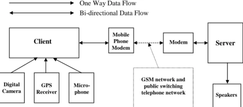
GSM mobile phone network which connects two major components[2], [3]. One component is the client which is installed inside the automobile to be monitored, and the other component, the server, acts like the central monitoring console. A GPS (global positioning system) receiver and other video and audio capturing devices are attached to the client so that the client can gather all these information and transmit them back to the server. On receiving the information from the client, the server will then display this information as shown in Figure 2 so that the operator of the system will be able to know exactly where the automobile is and what is going on inside and outside the automobile.
Server
Modem
GSM network and public switching telephone network Mobile
Phone Modem
Client
Digital Camera
GPS Receiver
Micro-phone
One Way Data Flow Bi-directional Data Flow
Speakers
Figure 1 Client/Server Model
2 Tasks to Perform
The primary concern of GG1 is to maximize the throughput of the low bandwidth mobile phone communication channel between the client and the server. Nevertheless, GG1 also requires a very complicated software structure since it has to support a list of different natured real time data collection and communication hardware during its operation.
There are totally seven main tasks to be completed in GG1:
capture location information from the GPS receiver,
capture video data from the video capturing device,
capture audio data from the audio capturing device,
data compression for the large volume of audio and video data captured,
data and controls transmission between client and server via modem,
reproduction of video, audio, location data received, and interpolation of GPS signals and display the resultant path on an electronic map
The operation mode mainly is responsible for presenting the data captured by the client system to the server system. On the top of the window, there are list of buttons and tool bars, which are provided for the operator to access the server’s window setting and control the operation of remote client system. Besides, the window divides into three partitions, which are for six major visual outputs. These visual outputs are displaying the map of interest, displaying the path traveled by the remote object, displaying pre-defined/expected path (way points), displaying result of interpolation of GPS data, indicating the current position of the remote object textually and display live video signals captured in the client side. The audio signals are also produced by sampling audio data in the client system. These are presented through the speakers.
3. Implementation
GG1 was written by Visual C++ as it has a lot of libraries, which assist the programmers to access the low-level implementations. Besides, user-friendly graphical interface can be implemented much more easily with this language. As it is an object-oriented language, the structure of this program should be in object-oriented. By creating different objects and designing the interactions between those objects, the software of this project is created.
3.1The Server
In the server system, there are six main objects, which include CServerView, CWayPointView, CServerDoc, CDial, CTrans and CDataMan.
CServerView Object
This object implements all the major jobs of the server system. It is responsible for all the displays. Moreover, it is also responsible to decompress the received video sequence, perform the interpolation of GPS data, generate the suitable portion of the map on the screen and make the control commands to client system. Producing audio output, buffering and decompressing the received audio data and as well as opening the audio output device are also the duties of this object.
CWayPointView Oject
This object implements all the user interface communications in edit mode.
CServerDoc Object
This object is responsible for the documentation of the received data. It records all the necessary data for CServerView object to display. This object records the last video sequence frame and the last received still picture. It also records the GPS data with a two-dimensional list.
CDial Object
This object is responsible for monitoring the connection between server and client systems. It encapsulates the functions of Telephone Application Programming Interface (TAPI) which is used to communicate with the modem. Therefore, this object can establish an outgoing call, answering an incoming call and hanging up an active call.
CTrans Object
This object is responsible for reading/writing the data from/to the com port.
CDataMan Object
As different types of data, including video, audio and GPS data, are transmitted, standardize data packing system should be employed. This object is designed for this purpose. Having received the compressed data, this object generates corresponding header, frame type, frame length and checksum to the front of the data. Footer is also generated and appended to the end. This whole set of data is called data frame and will be sent to CTrans object for transmission.
Receiving data frames is the same as sending but on reverse direction. The collected data frame is dispatched into raw data and sent to corresponding object for further processing.
3.2 The Client
The client system contains six major objects and other minor objects. The major
objects are CClientView, CDial, CTrans, CDataMan, CGPS and CVideoCap.
CClientView Object
This object is responsible to all the displays of the client window. It also needs to response the control commands sent from the server system by calling the member functions of the corresponding object.
CDial Object
This object works exactly the same as the CDial object of the server system.
CTrans Object
This object works exactly the same as the CTrans object of the server system.
CDataMan Object
This object works exactly the same as the CDataMan object of the server system.
CGPS Object
This object communicates with the GPS receiver directly.
CVideoCap Object
This object is responsible for capturing the video and audio data. It encapsulates the functions of Video For Window Application Programming Interface (VFW API). This object communicates and cooperated with the installed video capturing driver and the installed audio capturing driver for capturing the streaming video, streaming audio and high resolution still image.
Compressing the video and audio
data is also the responsibility of this
object. It cooperates with the Installable
Compression Manager (ICM) for video
compression and the Audio
Compression Manager (ACM) for audio
compression. After capturing a video
frame of the video sequence, the frame
will be compressed by the chosen video
compression codec. In this project, Intel
Indeo® Video R3.2 codec is employed.
The compressed frame will then pass to
the CDataMan object for packing into
the standard frame format and finally
send to the server system. The audio
samples are processed with the similar
procedures. They are compressed with a
chosen audio compression codec and
sent to CDataMan object.
4.
Multi-thread programming
Using multi-thread programming avoids the whole program to be idled while one of the processes in the program comes to a bottleneck state. In general, multi-thread programming speeds up response time while the program needs to manage more than one operation at the same time.
The real time response is very important target in this project. The client should perform the instructions from the server immediately after receiving them. However, the client may be very busy in packing and sending the previous requested data, since the size of video and audio data is extremely large even though, a small picture or a short period of sound is captured. Obviously, the single thread programming cannot satisfy this requirement. Besides, fast response user interface is also a major requirement of this project. As mention before, the multi-thread programming improves the efficiency of the multiple operations accession. As a result, multi-thread programming must be employed to this project.
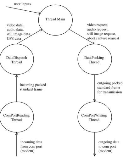
4.1 Threads in the Server System
Originally, three threads are designed for the server system to read data from the com port, to write data to the com port and to manage the flows of the program. However, after program testing, it was discovered that the program becomes non-responsive to the user input after one streaming data arrived. In order to increase the interactive of the program, two more threads are introduced. They are responsible for packing and dispatching the data. Resulting in these five threads, the program can work smoothly without any idle time.
Main Thread
This thread handles the main program flows.
DataDispatch Thread
This thread dispatch the standard frame sent from the ComPortReading Thread into raw data. Next, it checks the correctness of the data by examining the checksum. Then, it determines the type of the raw data by retrieving the header from the frame.
DataPacking Thread
This thread packs the raw data into standard frames for transmission.
ComPortWriting Thread
This thread writes the standard
frame sent from the DataPacking Thread
to the com port for delivering the frame
to the connected modem.
ComPortReading Thread
This thread reads data from the com
port.
ComPortReading Thread
ComPortWriting Thread DataDispatch
Thread
DataPacking Thread Thread Main
user inputs
video request, audio request, still image request, abort capture request video data,
audio data, still image data, GPS data
outgoing packed standard frame for transmission incoming packed
standard frame
incoming data from com port (modem)
outgoing data to com port (modem)
Figure 3 Flow diagram for the Server System
4.2
Threads in the Client System
Originally, There are four threads, which are reading data from the com port, writing data to the com port, capturing video, audio and GPS data and managing main program flows in this system. The main program flows involves handling the requests sent from server system, updating the displays, packing the data for further transmission, dispatching the data sent from server system, and manipulating the program data.
After the program testing, it was discovered that once the client starts to capture the streaming data according to the server request, the client system would become non-responsive to further requests. This may happen, as the thread of main program flows is too busy in packing the data captured by the multimedia capturing devices. Therefore, two more independent threads must be introduced to this system
mainly for packing the data for transmission and dispatching the data received from the server system.
Besides, it was also discovered that the outputs of streaming video and audio signals are not smooth enough as some pauses must be taken for the client system to communicate with the GPS receiver during the video and audio capture. Although this imperfection is acceptable for the video output, it is not tolerable for the audio case. It is because missing the audio samples will result in large distortion that makes the audio output completely incomprehensible. Moreover, the blocking in the communication between client system and the GPS receiver blocks the channel of capturing the multimedia data. As a result, the client system cannot obtain any new data from the remote object. This monitoring system is not secure at all. In order to avoid this tragedy, two more threads must be introduced for sending the instructions to the GPS receiver and
receiving the returning data. Finally, eight threads are employed in this client system.
Main Thread
This thread manages the main program flows of the client system.
DataDispatch Thread
This thread works exactly the same as the DataDispatch Thread of the server system.
DataPacking Thread
This thread works exactly the same as the DataPacking Thread of the server system.
ComPortWriting Thread
This thread works exactly the same as the ComPortWriting Thread of the server system.
ComPortReading Thread
This thread works exactly the same as the ComPortReading Thread of the server system.
ComPortReading Thread
ComPortWriting Thread DataDispatch
Thread
DataPacking Thread Main Thread
video request, audio request, still image request, abort capture request
outgoing packed standard frame for transmission incoming packed
standard frame
incoming data from com port (modem)
outgoing data to com port (modem) MultmediaCapturing
Thread
GPSReading Thread GPSWritting
Thread
capturing commands
video data, audio data, still image data
GPS data
asynchronous events, GPS position data text version of
asynchronous events initialization
requests
asychronous event request, position data request
Figure 4 Data Flow diagram for the Client System
5. Conclusion
GG1 was actually implemented. The client uses a Pentium-233 MMX laptop computer running Windows 95. It is equipped with a Connectix QuickCam black and white camera, a Garmin 45 GPS receiver and a modem connected to an Ericsson GH688 GSM mobile phone. The modem facilitates data transfer at between 2,400 and 9600 bps. A sound card connected with a microphone is also connected to the laptop for providing the sound capturing capability. The server is made up of a Pentium-133 MMX desktop computer running Windows 95.
After various testing and suitable amendments, the overall performance of the project can be concluded as satisfactory. All the major targets set at the beginning of the project are met. Low resolution streaming video, high resolution still image, streaming audio and GPS data can be captured and sent to the server system for display.
6. References
[1] Y.S. Moon, K. Wong, “GSM Mobile Phone Based Communication of Multimedia Information: A Case Study”, manuscript in preparation, 1999.
[2] R. J. Bates, Wireless Networked Communications, McGraw-Hill Inc., 1995.
[3] D. J. Goodman, Wireless Personal Communications Systems, Addison-Wesley, Jan 1998.