Version 4.0
Department of the Interior U.S. Geological Survey
USGS EOS SYSTEMS ENGINEERING
MANAGEMENT PLAN (SEMP)
Version 4.0
Executive Summary
This Systems Engineering Management Plan (SEMP) outlines the engineering
processes used by the LP DAAC staff in carrying out prototyping, system development, and sustaining engineering activities for systems at EROS.
Document History
Document Number Document Version
Publication
Date Change Description
LPDAAC-MP-000-028 1.0 Aug 2007
NA 2.0 Mar 2011 Full update of the
document.
NA 3.0 September
2012
Full review and update. Removed OVAs, updated
System V diagram, and added documentation about Report/Study Work
Packages.
NA 4.0 September
Contents
Executive Summary ... iii
Document History ... iv
Contents ... v
List of Figures ... vii
List of Tables ... vii
Section 1 Introduction ... 8
Section 2 Background ... 9
Section 3 Purpose and Scope ... 10
Section 4 Systems Engineering Process Overview... 11
Section 5 Development Life Cycle ... 13
5.1 Concept and Work Package Planning ... 16
5.1.1 Inputs ... 16
5.1.2 Key Activities ... 16
5.1.3 Products ... 17
5.1.4 Performance Indicators... 17
5.1.5 Methods and Tools ... 17
5.1.6 Exit Criteria ... 17
5.2 Design / Task Definition... 18
5.2.1 Inputs ... 18
5.2.2 Key Activities ... 18
5.2.3 Products ... 18
5.2.4 Performance Indicators... 18
5.2.5 Methods and Tools ... 19
5.2.6 Exit Criteria ... 19
5.3 Development ... 19
5.3.1 Inputs ... 19
5.3.2 Key Activities ... 19
5.3.3 Products ... 20
5.3.4 Performance Indicators... 20
5.3.5 Methods and Tools ... 20
5.3.6 Exit Criteria ... 21
5.4 Integration / Review ... 21
5.4.1 Inputs ... 21
5.4.2 Key Activities ... 21
5.4.3 Products ... 22
5.4.4 Performance Indicators... 22
5.4.5 Methods and Tools ... 22
5.4.6 Exit Criteria ... 22
5.5 System Test / Government Review ... 23
5.5.1 Inputs ... 23
5.5.2 Key Activities ... 23
5.5.4 Performance Inidicators ... 23
5.5.5 Methods and Tools ... 24
5.5.6 Exit Criteria ... 24
5.6 Delivery ... 24
5.6.1 Inputs ... 24
5.6.2 Key Activities ... 25
5.6.3 Products ... 25
5.6.4 Performance Indicators... 25
5.6.5 Methods and Tools ... 25
5.6.6 Exit Criteria ... 26
Section 6 Emergency Deliveries ... 27
Section 7 Organizational Roles ... 28
Section 8 Additional Processes ... 29
8.1 Portfolio Management Plan ... 29
8.2 Documentation Management Plan ... 29
8.3 Project Management Plan... 29
8.4 Schedule Management Plan ... 29
Appendix A Acronyms ... 30
List of Figures
Figure 4-1 Systems Engineering Process Overview ... 11
Figure 5-1 The System Engineering V ... 13
List of Tables
Table 5-1 Development Process Components ... 14Table 5-2 Process Components Milestones ... 15
Table 5-3 Process Components Milestones for Study/Report Work Packages ... 15
Table 5-4 Science Development Task... 16
Section 1 Introduction
The purpose of this document is to outline the process used by the LP DAAC for executing system development, system deployment, sustaining engineering and research projects. The engineering process framework outlines an overall process for systems and software engineering. The LP DAAC engineering process is tailored to EOS Project needs based on the TSSC engineering process framework. The LP DAAC process also uses several Project Management Institute (PMI) project management methods outlined in the book A Guide to the Project Management Body of Knowledge (PMBOK®) – Fourth Edition. PMBOK outlines five process groups of one or more processes each. The five groups are Initiating, Planning, Executing, Controlling, and Closing. All PMI process groups are repeated throughout the development life cycle. This document describes the process used for projects on the LP DAAC. The LP DAAC follows a structured process for its projects, from initial concept through to system
implementation. This model is sometimes referred to as the System Engineering V. On the left side of the V are the preparatory, planning, and development tasks. The right side of the V represents the implementation, testing, and finally deployment of the finished system. The approach to each part of the engineering process can be varied, but from a broad, high-level view, every system or project needs to traverse this V to become a deployed and operational system component in the LP DAAC, or become a finished prototype or research project. As described in the EOS Architecture document, the LP DAAC system components can be grouped into ECS Components, LP DAAC DUEs (DAAC unique extensions), USGS Enterprise Components, LP DAAC Internal Tools, LP DAAC Components of ECS, and Other NASA Components. All of these components are what is being referred to by this document as Systems. When updates to any of the LP DAAC systems are desired, this SEMP process will be followed to organize and execute those changes. In the case of systems and software to be implemented as a part of ECS from the ECS development team, only the right side processes shown in the System Engineering V will be executed at the LP DAAC (i.e. integration, testing and deployment). A set plan for working on LP DAAC systems is called a Work Package. The Work Package collects, contains, and organizes all the tasks that will be required to update or create the system and deploy it in the LP DAAC operational mode. The execution of a Work Package encompasses all of the System Engineering V. The System Engineering V is shown in Figure 5-1. The rest of this document describes each step needed in the V and what occurs during each step. Along with providing structure for the development of systems the SEMP also provides direction for the role of engineering support and operations in testing and implementing the developed system. After system development, enough supporting documentation for the project should exist to support and assist the activities of the User Services and Operations groups to maintain and operate the deployed system.
Section 2 Background
The Land Processes Distributed Active Archive Center (LP DAAC) was established as part of NASA's Earth Observing System (EOS) Data and Information System (EOSDIS) initiative to process, archive, and distribute land-related data collected by EOS sensors, and thereby promote an inter-disciplinary study and understanding of the integrated Earth system. The role of the LP DAAC includes the higher-level processing and distribution of ASTER data, and the distribution of MODIS land products derived from data acquired by the Terra and Aqua satellites.
The LP DAAC project system requirements are primarily met through the NASA's Earth Observing System (EOS) Data and Information System (EOSDIS) Core System (ECS). Other requirements not fulfilled by the ECS are the responsibility of internal engineering efforts of the LP DAAC. This SEMP governs all engineering and implementation for both deployments of ECS software and development and planning of DAAC specific components.
Section 3 Purpose and Scope
This document describes a high level engineering process for LP DAAC projects. This document is intended to serve as an engineering guide for general development, testing, implementation, and deployment of Work Packages. Both required and
suggested practices are outlined in this document. Artifacts that are created throughout the engineering process are identified.
Section 4 Systems Engineering Process Overview
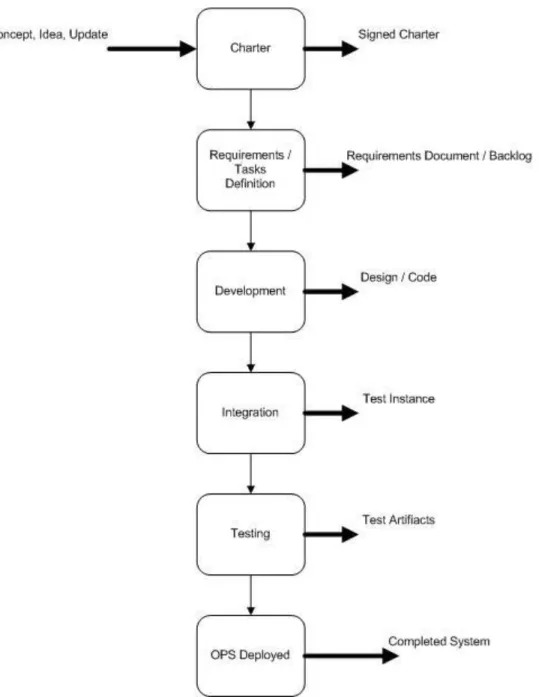
The basic objective of systems engineering is to enable a work process to produce a desired outcome. A top-level view of the LP DAAC’s systems engineering is shown in Figure 4-1 Systems Engineering Process Overview. This figure shows a full process for engineering a new system from a concept, but other projects may only have a subset of these tasks or begin or end at a different level. For example, a project to implement already developed code would start at integration. A project to adjust configuration could begin at the Testing phase.
The systems engineering process is concerned with the following activities defined below:
All engineering activities on the LP DAAC start with a Charter that is a basic description of the work to be done.
Design / Task analysis is the process of building a set of well-formed designs or tasks, which capture the higher-level customer and stakeholder objectives.
Development is the process of transforming well-formed designs or tasks into functional system components.
Integration occurs when the system is ready to be implemented in the test environment as a full system with all subsystems developed and ready.
System Testing occurs after the integration. A test instance is identified and system tests are performed against the system.
OPS deployment and Operational Verification occurs after the successful
completion of system testing. Upon operational verification, the project is cleared to move into full time production and the development of the project is complete. Prototype and Pilot system engineering Work Packages might not go all the way to the OPS deployment phase and may stop at the System Test phase. The moving of a prototype or pilot Work Package to a system fully deployed in OPS would have to be covered by a follow-up Work Package.
Occasionally, a Work Package is requested to provide a study or report on a current technology, or to create user documentation or perform a support task. In this case the Work Package would encompass an alternate set of activities:
The Charter will define the topics to be studied and the level of the study or task.
An analysis of the activities needed to complete the study/report will be generated.
The report, study, or support task will be carried out.
A review of the report may be performed by TSSC and the USGS.
The finalized report, study, or support task will be delivered to the USGS.
In the case of supporting documentation developed for a Work Package, the results may be posted to the LP DAAC website through Docushare (the LP DAAC’s Content Management System).
Section 5 Development Life Cycle
In order to deliver systems reliably and in a timely manner, an engineering process must be followed. This process is generally referred to as the engineering life cycle. A
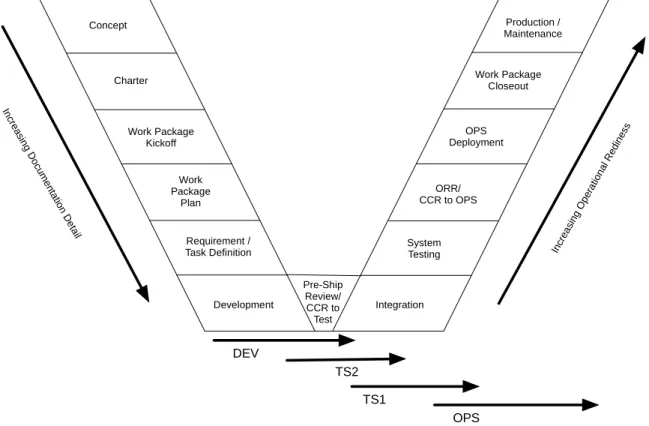
common engineering lifecycle model is the System Engineering V. Figure 5-1 outlines the System Engineering V.
Concept Charter Work Package Plan Requirement / Task Definition Development Integration System Testing ORR/ CCR to OPS
OPS Deployment
Production / Maintenance
In crea
sing Do cum en ta tion D e tail Incr ea sin g O
pe ratio na l R ed ine ss Work Package Kickoff DEV TS2 TS1 OPS Pre-Ship Review/ CCR to Test Work Package Closeout
Figure 5-1 The System Engineering V
The System Engineering V model of system engineering moves through key phases, one at a time, completing each phase before moving on to the next. Extra detail is added to the process as the system moves through design, development, and implementation phases. System Testing provides verification of the required functionality actually present in the developed system. Once the system passes
Operational Readiness Review (ORR), it is deployed to production. After that the Work Package Closeout closes the project, which then continues in productive operation. The definition of the requirements and/or the required development tasks defines the activities that will be taking place during development. The Development step allows software developers to begin designing and coding the system based on their preferred style. Developers may choose to outline the design first, and then add code, or they may choose to create the design by writing code first and documenting the design details.
The Integration and System Testing phases of the V begin the process of moving the developed new system towards operational status. Integration activities include setting up the test environment and preparing for building and deploying to the operational environment. On the LP DAAC there are as many as four different environments (self contained areas for the application to run) that a project can be deployed to. Those environments are:
DEV – The development environment. This environment is optional or may exist solely on developer PCs, but shared dev environments can be deployed on servers as well if needed.
TS2 – The first test mode. In some cases this mode can act as a dev environment, or it can be the first integrated testing mode.
TS1 – The test mode. This is the mode System Testing takes place in before deployment to the operational mode.
OPS – The operational mode. This is the mode that the application runs in. For public applications, this is the mode that is visible to the world.
Operational deployment and functional operation of the project will follow successful completion of the System Test and the ORR. After successful deployment in OPS the Work Package Closeout occurs and the project officially finishes.
Work Package Closeouts can occur at any point in the process if a project is cancelled. In this case they will still mark the completion of work against the Work Package, even though an operational deployment was not achieved.
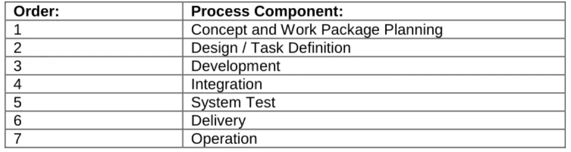
The following sections of the SEMP provide a higher-level detail of each process within an iterative development cycle (See Table 5-1).
Order: Process Component:
1 Concept and Work Package Planning 2 Design / Task Definition
3 Development
4 Integration
5 System Test
6 Delivery
7 Operation
Table 5-1 Development Process Components
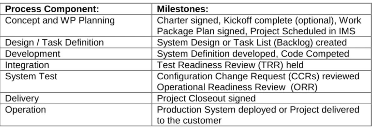
Each phase has required and suggested deliverables. The deliverables are broken up into supporting documentation (inputs), Project Deliverables, and activities. Each phase concludes with a milestone as shown in Table 5-2.
Process Component: Milestones:
Concept and WP Planning Charter signed, Kickoff complete (optional), Work Package Plan signed, Project Scheduled in IMS Design / Task Definition System Design or Task List (Backlog) created Development System Definition developed, Code Competed Integration Test Readiness Review (TRR) held
System Test Configuration Change Request (CCRs) reviewed Operational Readiness Review (ORR)
Delivery Project Closeout signed
Operation Production System deployed or Project delivered to the customer
Table 5-2 Process Components Milestones
Documents and project deliverables support the work that must occur during each phase.
Milestones are the last check-off and approval before beginning the next phase. This action confirms the work performed in the phase that was completed. During the life cycle, milestones are reviewed with the customer and subsequent phases may or may not gain approval. During the development phase, periodic reviews may be conducted to review the progress of development tasks. For projects utilizing agile methods during development, these periodic reviews are mandatory.
Activities are tasks that occur to support the deliverables of each phase. Study or Report Work Packages
For study/report based Work Packages the Task Definition, Development, Review (System Test) and Delivery (the OVA and Operation sections) are the only process components that need to be completed. This is shown in Table 5-3.
Process Component: Milestone:
Concept and WP Planning Charter signed, Kickoff complete (optional), Work Package Plan signed, Project Scheduled in IMS Task Definition Tasks for the Work Package defined. Report
and/or Study deliverables identified. Development (Report Creation) Study executed, report developed. Review (Integration) Document Review TSSC
Customer Review (System Test) Document Review USGS
Delivery Report/Study accepted by customer.
Table 5-3 Process Components Milestones for Study/Report Work Packages
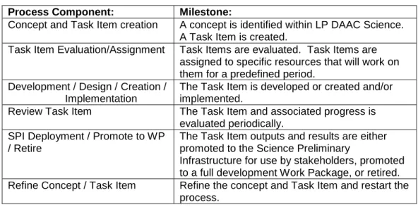
Science Development Task
Preliminary development work can be undertaken by the LP DAAC Science Task. Work occurring within Science is likely associated with key LP DAAC stakeholders or related to specific work for the LP DAAC Scientists. The process components and milestones and outputs for Science Development differ from general development Work Packages and from Study/Report Work Packages.
Process Component: Milestone:
Concept and Task Item creation A concept is identified within LP DAAC Science. A Task Item is created.
Task Item Evaluation/Assignment Task Items are evaluated. Task Items are assigned to specific resources that will work on them for a predefined period.
Development / Design / Creation / Implementation
The Task Item is developed or created and/or implemented.
Review Task Item The Task Item and associated progress is evaluated periodically.
SPI Deployment / Promote to WP / Retire
The Task Item outputs and results are either promoted to the Science Preliminary
Infrastructure for use by stakeholders, promoted to a full development Work Package, or retired. Refine Concept / Task Item Refine the concept and Task Item and restart the
process.
Table 5-4 Science Development Task
Science Development represents a sort of pre-development phase for the study of concepts and issues before they are promoted to full development work.
5.1
Concept and Work Package Planning
The first step in any project is to examine its scope and create a plan for it. This is primarily a project management activity; however, systems engineers play a key technical role in establishing the scope of work for the project manager.
The Concept and Work Package Planning phase is mandatory and may not be skipped for any project. The activity may be scoped as appropriate for the project at hand. A project charter is required in all cases. If the project is deemed large enough to require it a Work Package Plan must also be created. The creation of the Work Package Plan follows the signing of the charter. The completion of a kick-off meeting is meant to provide a discussion about the Work Package with all stakeholders, for certain projects it is optional.
5.1.1 Inputs
Input artifacts are artifacts that are requi red before the Concept and Planning phase may proceed.
1. Project Charter 5.1.2 Key Activities
3. Planning and scoping engineering activities 4. Risk assessment
5. Develop Kick-off documentation 6. Develop Work Package Plan 5.1.3 Products
Products will be generated as required for Work Packages. Documents that are mandatory will be indicated as such.
1. Charter (Required)
2. Schedule Request Form (SRF) completed
3. Work Package Plan (Required, size and detail scaled to the complexity of the Work Package)
a. Initial operations concept (diagram) b. Requirements/tasks
c. Schedule and budget estimates d. Risk Assessment
e. Contingency Plan
4. Scheduled into the Integrated Master Schedule (IMS)
5. Kick-off meeting (optional, Can precede Work Package Plan) 5.1.4 Performance Indicators
The following indicators can be used to determine the performance of the process during this phase.
1. Project objectives and deliverables defined 2. Work Package scheduled
5.1.5 Methods and Tools
The various methods and tools used to complete the Concept and Planning phase. Included are templates for some of the artifact products of this phase.
1. Project Charter Template 2. Work Package Plan Template 3. Schedule Request Form
4. Integrated Master Schedule (IMS) 5. Kick-off meeting briefing template 5.1.6 Exit Criteria
The following criteria are required to be met before the Concept and Planning phase can be complete.
1. USGS customer signature on the Charter 2. Work Package Plan signed by USGS customer
3. Work Package Prioritized by the USGS customer per the USGS EOS Portfolio Management Plan.
4. SRF completed and put into IMS 5. Kick-off meeting completed (optional)
5.2
Design / Task Definition
The design / task definition phase is used to create the design or tasks necessary to complete the project. The initial requirements or tasks are identified before
development can occur. Lower level requirements or tasks can be identified during this phase, but are not required.
5.2.1 Inputs
Input artifacts are required before the Requirements Development phase may proceed.
1. Work Package Plan
2. High level operations concept diagram 3. Work Plan requirements or tasks (backlog)
4. Existing requirements (if enhancement or replacement of current system) 5. Existing operations concept (if enhancement or replacement of current system) 6. Stakeholder Input
5.2.2 Key Activities
These are the key actions that may occur during this phase. 1. Design / task development
2. Functional architecture planning 3. Interface requirements
5.2.3 Products
Products are generated as required for Work Packages. Documents that are mandatory will be indicated as such.
1. Operational Concept document (OPSCON) 2. Design plan / task backlog (Required) 3. Draft functional architecture
4. Draft Interface Control Documents (ICD) 5. Change Requests
6. Schedule modifications to the IMS 5.2.4 Performance Indicators
The following indicators can be used to determine the performance of the process during this phase.
5.2.5 Methods and Tools
There are various methods and tools that are used to complete the Requirements Development phase. Included are templates for some of the artifact products of this phase.
1. Operational Concept template (OPSCON) 2. Design plan / Task backlog spreadsheet 3. Project scheduling software
5.2.6 Exit Criteria
The following criteria are required to be met before the Concept and Planning phase can be complete.
1. Enough Design detail / Task detail defined to begin Development
5.3
Development
The Development phase is where all the software design and coding for the project will be taking place. Before beginning the Development phase the high level requirements for the system should be defined. However, as the Work Package progresses
requirements or tasks may continue to be identified. Requirements discovered must be added to the requirements document or task backlog and their effect on the schedule determined. For various reasons, requirements may also need to be removed from the project, or discovered requirements will need to be rejected due to an undesired impact they may cause for the project.
At the end of the Development phase a software release will be identified as the test candidate. The test candidate will undergo a unit testing process. Once unit testing is completed the Integration phase may begin. Before testing begins, the software should be stored to a source code repository and identified in the repository as the testing candidate. For Study or Report Work packages the Development phase is where the report/study is created.
5.3.1 Inputs
Input artifacts are required before the Development phase may proceed. 1. Initial Requirements / Task List
5.3.2 Key Activities
These are the key tasks that may occur during this phase. 1. System Design
2. System Coding 3. Unit Testing
4. Re-planning if changes have occurred 5. Software Release
6. Identification of Test Candidate 7. Architecture Design
8. Database Design 9. Trade Studies
10. Interface Control Documents (ICD) 11. Risk Mitigation/Escalation (if necessary)
12. Requirements Review (Addition and deletion of requirements) 13. Infrastructure configuration and tuning
14. Develop System Test plan
5.3.3 Products
Products are generated as required for work packages. Documents that are mandatory are indicated as such.
1. System Code (Required for software projects) 2. Software Releases
3. Test Candidate Releases 4. Software Design Documents 5. Database Design Documents 6. Functional Architecture
7. Implementation Plan / Instructions (Required for software projects) 8. Interface Control Document
9. Operations Concept 10. Unit Test Plan(s) 11. Security Plan
12. Study or Report Document (Required for Study/Report projects) 5.3.4 Performance Indicators
The following indicators can be used to determine the performance of the process during this phase.
1. System Operational in TS2/TS1 Mode 2. Speed of Development
3. Conformance to Schedule 4. Stakeholder/Customer Review Or for Report or Study Work Packages: 1. Report/Study Length or Level of detail 5.3.5 Methods and Tools
5.3.6 Exit Criteria
The following criteria are required to be met before the Synthesis and Design phase can be complete.
1. Integration ready build of system 2. All requirements documented
3. Requirements met by the system implemented
For Report or Study Work Packages, the exit criteria are: 1. Reviewable Report.
5.4
Integration / Review
Following the Development phase, the project is integrated into one of the test modes. The system can be implemented in one of the test modes (TS1 or TS2). The goal of the integration phase is to create a complete system implementation that can have the System Test executed against it. At the end of the Integration phase the Test Readiness Review (TRR) will be conducted. The outcome of the TRR will be a Configuration Change Request (CCR) to implement either the TS1 instance or to
execute the system test against the current installed test instance. For Report or Study Work Packages the integration phase is where the report is reviewed by TSSC staff.
5.4.1 Inputs
Input artifacts that are required before the Integration phase may proceed. 1. System Code
2. Integration Plan / Instructions Or for Report/Study Work Packages: 1. Report or Study
5.4.2 Key Activities
These are the key tasks that may occur during this phase. The activities performed may change from iteration to iteration.
1. Integration into Test Mode
2. Infrastructure configuration and tuning 3. Integration Testing
4. Develop System Test plan
Or for Report/Study Work Packages: 1. Report or Study review by TSSC.
5.4.3 Products
Products are generated as required for work packages. Documents that are mandatory are indicated as such.
1. System Test Plan (Required) 2. Integrated System
3. Final Turnover Package Including (Software Release Notes) 4. Test Case to Requirement matrix (optional)
5. User Guides
6. Test Readiness Review (TRR) (Required)
7. Configuration Change Request (CCR) (Required) Or for Report/Study Work Packages:
1. Feedback and Comments 5.4.4 Performance Indicators
The following indicators can be used to determine the performance of the process during this phase.
1. System Operational in test mode (TS2 or TS1) Mode Or for Report/Study Work Packages
1. Number of Comments 5.4.5 Methods and Tools
There are various methods and tools used to complete the Integration / Review phase.
1. Document Templates 5.4.6 Exit Criteria
The following criteria are required to be met before the Integration / Review phase can be complete.
1. Integration Testing completed 2. System Test Plan completed 3. TRR signed off by Work Manager 4. CCR signed off by Customer For Report/Study Work Packages
5.5
System Test / Government Review
After integration the running system will be available for the system test. The system test will be executed against the system to ensure that the system meets all
requirements. Once all system tests have been passed or addressed, the system will move on to operational installation and then to operational verification. For Report or Study Work Packages the System Test phase is when the report is reviewed by USGS staff.
5.5.1 Inputs
Input artifacts that are required before the System Test phase may begin. 1. System integrated and ready for testing
2. System Test Plan (STP) 3. User Guides
Or for Report/Study Work Packages: 1. Report or Study Document
5.5.2 Key Activities
These are the key tasks that may occur during this phase. 1. Execution of System Test Plan
2. Track and resolve Trouble Tickets (TT, optional) 3. Operator / User training
Or for Report/Study Work Packages: 1. Report or Study reviewed by USGS.
5.5.3 Products
Products will be generated as required for Work Packages. Documents that are mandatory will be indicated as such.
1. System Test Report (Required)
2. Operations Readiness Review materials Or for Report/Study Work Packages:
1. Feedback and Comments 5.5.4 Performance Inidicators
The following indicators can be used to determine the performance of the process during this phase.
1. Percent of System Tests completed 2. Trouble Tickets created
3. Number of Trouble Tickets resolved
4. Number of Trouble Tickets deferred to later release Or for Report/Study Work Packages
1. Number of Comments
5.5.5 Methods and Tools
There are various methods and tools used to complete the Synthesis and Design phase.
1. Document templates 5.5.6 Exit Criteria
The following criteria are required to be met before the System Test phase can be complete.
1. Completed Operations Readiness Review (ORR/Pre-CCB) 2. Completed Systems Test Report.
3. Formal signoff from USGS customer on CCR to enter OPS. For Report/Study Work Packages
1. Report/Study updated based on comments/feedback
5.6
Delivery
The Delivery phase is the activity of running new systems through final confirmation of capabilities in the operational environment during a specified time period. Operators of the system execute all functions of the system to verify that all functions are functioning correctly.
For Report/Study work packages the only thing required from the delivery phase are signatures on the delivered Documentation and for the document to be archived in the LP DAAC document management system.
5.6.1 Inputs
Or for Report/Study Work Packages
1. Report fully updated based on comments/feedback from both TSSC and USGS. 5.6.2 Key Activities
These are the key tasks that may occur during this phase. 1. Operation of the system
2. User / Operator acceptance verification
3. Resolution of issues through Change Requests. Or for Report/Study Work Packages
1. Formal Document Delivery to USGS, including signatures 5.6.3 Products
Products will be generated as required for Work Packages. Documents that are mandatory will be indicated as such.
1. Closeout report for the Work Package Or for Report/Study Work Packages 1. Signed Report/Study Document 5.6.4 Performance Indicators
The following inidicators can be used to determine the performance of the process during this phase.
1. Number of Configuration Change Requests (CCR)s generated by Operations (lower is better, none is best)
2. Number of Trouble Tickets identified 3. Number of Issues fixed
Or for Report/Study Work Packages 1. Document Signatures
5.6.5 Methods and Tools
The various methods and tools used to complete the Operational Verification Acceptance phase.
1. Closeout Template 2. CCR form
5.6.6 Exit Criteria
The following criteria are required to be met before the Operational Verification Acceptance phase can be complete.
1. All relevant CRs not associated with accepted issues should be closed 2. Closeout Report for the Work Package
Or for Report/Study Work Packages 1. Signed Report/Study Document
Section 6 Emergency Deliveries
The need occasionally arises to make a quick change to the system due to problems that arise. If the problem is deemed large enough, this will require an emergency delivery. An emergency delivery is a delivery of a set of changes to a system which must be made on a very short time scale to meet or continue to meet customer
requirements. Generally an emergency deliverable should only be required if there is a significant problem in operation of the system or a major failure of a system component (either hardware or software).
The concept and planning phase required in the case of an emergency may be as little as an e-mail from the USGS customer detailing the requirements that need to be met by an emergency delivery. The requirements definition phase may be skipped if the
requirements are completely stated in the customer e-mail. A Trouble Ticket may express the requirements of an Emergency Release as well. The e-mail emergency requirements will be considered the CCR if they are complete enough to proceed. If not requirements will be refined and a desk review of those requirements will be conducted with the USGS customer.
The Development phase is defined by the work to be performed. Unit Testing and Integration Testing are required. Acceptable UT and IT tests may be drawn from the set of UTP and ITP documents from the latest release of the system in question. The
Emergency Fix will generate an emergency CCR.
The system test phase must at least be partially executed. The last release STP should be used to draw tests from. Critical operational functionality should be tested but non-critical STP procedures may be omitted.
The USGS customer must approve the move of the system into operations. USGS customer approval to enter into operations must be obtained at least in email form or through a desk review as a signed emergency CCR.
In the case of an emergency delivery, the operational verification and acceptance period takes on special importance. Systems engineering staff should work with operations staff to follow up with additional system testing to verify that the non-critical system functions were not adversely affected by the emergency delivery.
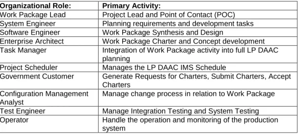
Section 7 Organizational Roles
This section is intended to provide a general indication of the responsibilities of key organizational positions. In practice a staff member may fill part or all of several roles, or a staff member may specialize and only perform a portion of those activities listed within a particular role. Further information on informational roles can be found in the LP DAAC Responsibility Assignment Matrix. Basic roles and activities for the LP DAAC are shown in Table 7-1.
Organizational Role: Primary Activity:
Work Package Lead Project Lead and Point of Contact (POC) System Engineer Planning requirements and development tasks Software Engineer Work Package Synthesis and Design
Enterprise Architect Work Package Charter and Concept development Task Manager Integration of Work Package activity into full LP DAAC
planning
Project Scheduler Manages the LP DAAC IMS Schedule
Government Customer Generate Requests for Charters, Submit Charters, Accept Charters
Configuration Management Analyst
Manage change process in relation to Work Package Test Engineer Manage Integration Testing and System Testing Operator Handle the operation and monitoring of the production
system
Section 8 Additional Processes
This section describes basic system engineering processes that may also be applied within an LP DAAC project.
8.1
Portfolio Management Plan
The USGS EOS Portfolio Management Plan details the methodology for determining priority for work that is undertaken by the LP DAAC. All Work Packages undertaken by the LP DAAC are given a priority that is tracked by the project. The Portfolio
Management Plan is located in DocuShare at Home >> Project Management >> 1.1 Project Management >> 1.1 Management Plans Listing >> Portfolio Management Plan.
8.2
Documentation Management Plan
The Document Management Plan provides details on the handling of document artifacts for Work Packages. The DMP is available in DocuShare at Home >> Project
Management >> 1.1 Project Management >> 1.1 Management Plans Listing >> USGSEOS-MP-000-021 Document Management Plan.
8.3
Project Management Plan
The LP DAAC Project Management Plan details the processes for managing the LP DAAC at the highest level. The SEMP is a key reference for the Project Management Plan. The PMP is available in DocuShare at Home >> Project Management >> 1.1 Project Management >> 1.1 Management Plans Listing >> Process & Project Management Plan.
8.4
Schedule Management Plan
The LP DAAC Schedule Management Plan details the processes and procedures for managing the LP DAAC Integrated Master Schedule (IMS). The SMP is available in DocuShare at Home >> Project Management >> 1.1 Project Management >> 1.1 Management Plans Listing >> EOS Schedule Management Plan.
Appendix A Acronyms
CCR Configuration Change Request
CM Configuration Management
CMA Configuration Management Analyst
COTS Commercial Off The Shelf
CR Change Request
DBDD Database Description Document
DEV Development Mode
DOI Department of the Interior
ECS EOSDIS Core System
EDC EROS Data Center
EOS Earth Observing System
EOSDIS EOS Data Information System
EROS Earth Resources Observation and Science
HDD Hardware Design Document
ICD Interface Control Document
IMS Integrated Master Schedule
IMS Integrated Master Schedule
IT Integration Test
ITP Integration Test Plan
ITR Integration Test Report
LP DAAC Land Processes Distributed Active Archive Center
MMO Mission Management Office
NASA National Aeronautics and Space Administration
OPS Operational Mode
OPSCON Operations Concept document
ORR Operations Readiness Review
OVA Operations Verification Acceptance
SDD Software Design Document
SE Systems Engineer
SEMP Systems Engineering Management Plan
SRD Software Requirements Documents
ST System Test
STP Systems Test Plan
STR Systems Test Report
SWE Software Engineer
TDR Test Discrepancy Report
TRR Test Readiness Review
TS1 Test Mode 1
TS2 Test Mode 2
USGS United States Geological Survey
References
USGS EOS Architecture Description Document, Version 2.5, June 2013 USGS EOS Configuration Management Plan, Version 1.2, November 2010 USGS EOS Project & Process Management Plan, Version 2.1, June 2009 USGS EOS Schedule Management Plan, March 2012