I
NTERB
US-S
Product Description
The IPS IP I/O Gateway is functionally equivalent to two normal I/O modules with cross-connected inputs and outputs.
Features
- InterBus-S protocol (DIN E 19258)
- Connectors for supply voltage and bus connections - Electrical isolation of the
coupled InterBus-S lines - Diagnostic LEDs
- Degree of protection IP 67 - Mounting compatible with
machine construction needs
Application
The unit couples two lines of the extended installation remote bus in harsh industrial environments. This allows, for example, to exchange start or stop signals between two host systems.
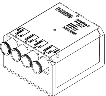
IBS IP I/O Gateway
Data Sheet
Coupling Module for Two InterBus-S Lines
08/1995 Data Sheet Version A
Fig. 1: IBS IP I/O Gateway
5025A001
Courtesy of Steven Engineering, Inc.
Ÿ
230 Ryan Way, South San Francisco, CA, 94080
-6370
Ÿ
Main Office: (650) 58
8-9200
Ÿ
Outside Local Area: (800) 25
8-9200
Ÿ
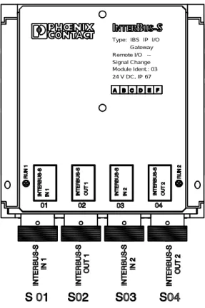
Fig. 2: Locations of connectors
Module Ident.: 03 Remote I/O --Type: IBS IP I/O
Signal Change Gateway
24 V DC, IP 67
DC/DC
Electrical isolation
INTERBUS IN 1
INTERBUS IN 2
INTERBUS OUT 1
INTERBUS OUT 2 24 V DC
24 V DC
5025A016
REGISTER 2
REGISTER 1
DC/DC
Fig. 3: Block diagram (illustration)
As shown in the block diagram (Fig. 3), each of the two InterBus-S lines must have its own voltage supply to ensure that each of the two InterBus-S lines works independently:
Courtesy of Steven Engineering, Inc.
Ÿ
230 Ryan Way, South San Francisco, CA, 94080
-6370
Ÿ
Main Office: (650) 58
8-9200
Ÿ
Outside Local Area: (800) 25
8-9200
Ÿ
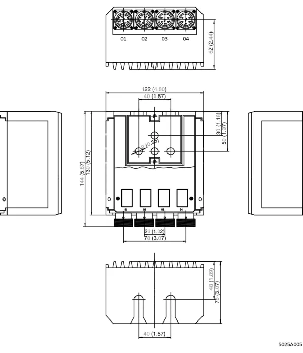
Mechanical Dimensions
Fig. 4: Mechanical dimensions (given in mm (inches)) 04
03 02 01
5025A005
Courtesy of Steven Engineering, Inc.
Ÿ
230 Ryan Way, South San Francisco, CA, 94080
-6370
Ÿ
Main Office: (650) 58
8-9200
Ÿ
Outside Local Area: (800) 25
8-9200
Ÿ
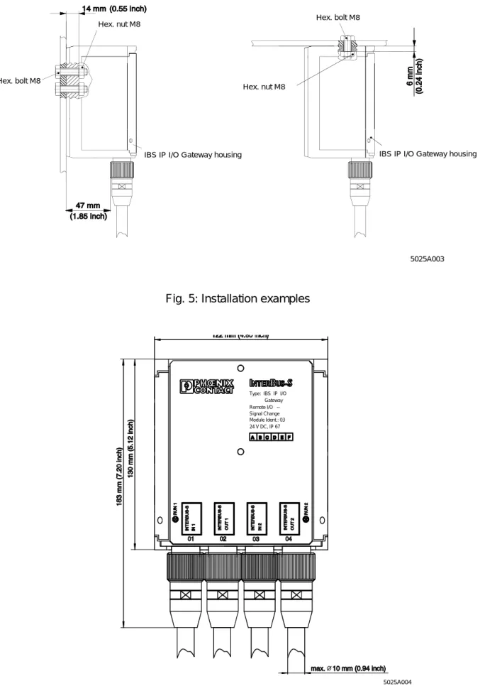
Connection
Fig. 5: Installation examples
Figure 6: Cabling example
Hex. bolt M8
IBS IP I/O Gateway housing
Hex. nut M8
IBS IP I/O Gateway housing Hex. nut M8
Hex. bolt M8
5025A003
Module Ident.: 03 Remote I/O --Type: IBS IP I/O
Signal Change Gateway
24 V DC, IP 67
5025A004
Courtesy of Steven Engineering, Inc.
Ÿ
230 Ryan Way, South San Francisco, CA, 94080
-6370
Ÿ
Main Office: (650) 58
8-9200
Ÿ
Outside Local Area: (800) 25
8-9200
Ÿ
Connection
5076A012
- Push the cap (1), flexible ring (2), strain relief with O-ring (3) and washer (4) onto the cable - Strip off the outer cable sheath 22 mm
- Remove braided screen from the conductor and turn it to the outside at an angle of 90°
- Push the shield washer (6) before the braided screen (5) so that the braided screen is between washer(4) and shield washer (6)
- Cut off projecting braided screen (5) - Stripp off core ends 3mm
- Solder the contact insert (8) as shown in the pole diagram
3 mm
22
- Push-on the stopper (7), then push strain relief (3) against washer (4) and the flexible ring (2) under the strain relief (3)
- Push the cap sleeve (10) onto the cable, the side with the internal thread first
- Push the contact sleeve (9) in such a way onto the contact insert that the sleeve's guide pin (11) fits exactly into the slot of the contact sleeve (8)
2
4 3
5
4 6
8
7 2
3 4
10 9
8
11
12
max 0.2 mm
1
1
- Hold the contact sleeve with the assembly tool (12) and tighten the cap (1) with a wrench (22 mm) until end stop, do not turn the assembly tool but the cap!
- The cap sleeve may have a max of 0.2 mm clearance.
Courtesy of Steven Engineering, Inc.
Ÿ
230 Ryan Way, South San Francisco, CA, 94080
-6370
Ÿ
Main Office: (650) 58
8-9200
Ÿ
Outside Local Area: (800) 25
8-9200
Ÿ
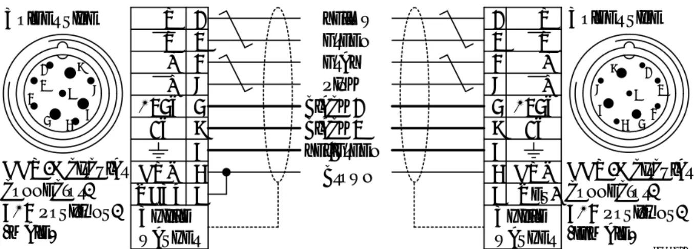
Pin assignment
Fig. 8: Cable diagram of the extended remote bus cable (cable type CCO-E/CCO-E)
General
Degree of protection IP 67
Permissible operating temperature From - 20 °C to + 55 °C Permissible storage temperature From - 30 °C to + 75 ° C Housing dimensions (w*h*d) 122 mm* 130 mm* 78 mm
Housing Aluminium-cast, sealed (without silicone)
Installation Suitable for machine construction with M8
bolts (provide a secure electrical contact between module housing and PE)
Installation position: As desired
Bus interface InterBus-S, RS 485, 500 kbits/s
Extended installation remote bus, circular con-nector for the extended installation remote bus
Permissible cable length Max. 50 m between two modules
I/O functions
-external None connectable
-internal 16-bit output of InterBus-S no.1 connected
with 16-bit input of InterBus-S no.2,
16-bit output of InterBus-S no.2 connected with 16-bit input of InterBus-S no.1
Supply of the Module Electronics
Operating voltage Supplied by InterBus-S connector
-Nominal value 24V DC
-Permissible range 18 to 30 V DC
-Feeding in Separate for InterBus-S no.1 and no.2
Current consumption 100mA per InterBus-S line
Insulation voltage (operating voltage/ 500 V AC InterBus-S no.1/InterBus-S no.2)
Local Diagnostic Indicators
RUN 1 green LED InterBus no.1 supply voltage
RUN 2 green LED InterBus no.2 supply voltage
Solder side 1
2 3 4 5 6 7 8 9 DO DO DI DI +24V COM 0V RBST yellow green gray pink black 1 black 2 yel/green brown 1 2 3 4 5 6 7 8 9 DO DO DI DI +24V COM 0V Res. Solder side 5066B011 Shield washer Shield washer CCO-E circular connector, 6+3 positions, (male) 1 2 3
4 5 6
7 8 9 1 2 3 4 5 6 7 8 9 CCO-E circular connector, 6+3 positions, (female)
Courtesy of Steven Engineering, Inc.
Ÿ
230 Ryan Way, South San Francisco, CA, 94080
-6370
Ÿ
Main Office: (650) 58
8-9200
Ÿ
Outside Local Area: (800) 25
8-9200
Ÿ
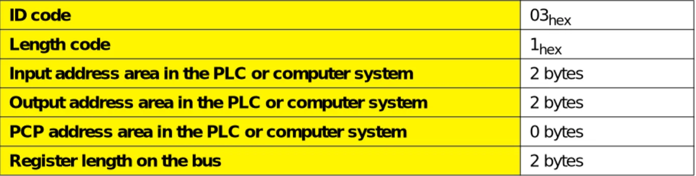
Table 1: InterBus-S programming data
Table 2: Ordering data
ID code 03hex
Length code 1hex
Input address area in the PLC or computer system 2 bytes
Output address area in the PLC or computer system 2 bytes
PCP address area in the PLC or computer system 0 bytes
Register length on the bus 2 bytes
Description Type Order No.
I/O distribution box / coupling module for two InterBus-S lines
IBS IP I/O Gateway 27 52 04 2 Cable for the extended remote bus, in meters (hybrid
cable, 3* 2* 0.25 mm2 + 3* 1.5 mm2)
IBS EINBC METER 27 52 10 7 Cable assembly for the extended installation remote
bus (male, female connector and soldering)
IBS EIN CCO-KONFEK
on request Set of circular connectors, for the extended
installation remote bus, 9-pos., solder connection, male/female
IBS EIN CCO-R/L 27 52 09 7
Assembly tool for circular connector IBS CCO MT 27 58 32 1
Adapter for feeding the supply voltage into the extended installation remote bus
IBS IP P-ADAP-E 27 52 07 1 Adapter for switch cabinet side panel, connects IBS
devices in the switch cabinet with the I/O distribution boxes
IBS IP ADAP-E 27 52 08 4
Courtesy of Steven Engineering, Inc.
Ÿ
230 Ryan Way, South San Francisco, CA, 94080
-6370
Ÿ
Main Office: (650) 58
8-9200
Ÿ
Outside Local Area: (800) 25
8-9200
Ÿ
Addre
s
s
A
s
s
ignment
5025A
P
hoenix
C
ont
ac
t
G
m
b
H
&
Co.
Pos
tfach
1341
32819
B
lom
berg
G
ermany
8
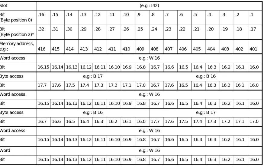
Table 3: Relative assignment of addresses between different hosts
* Byte position 2 can only be accessed with logical addressing.
** The representation for IBM PCs is valid only for word-based access to the process data.
For the controller boards IBS PC CB/I-T and IBS PC CB/COP/I-T it is valid only when the macros for process data conversion are used.
AEG A250 (DIN addresses)
Slot (e.g.: I42)
Bit
(Byte position 0)
.16 .15 .14 .13 .12 .11 .10 .9 .8 .7 .6 .5 .4 .3 .2 .1
Bit
(Byte position 2)*
.32 .31 .30 .29 .28 .27 .26 .25 .24 .23 .22 .21 .20 .19 .18 .17
Klockner-Moeller IPC620
Memory address,
e.g.: 416 415 414 413 412 411 410 409 408 407 406 405 404 403 402 401
Bosch Word access e.g.: W 16
Bit 16.15 16.14 16.13 16.12 16.11 16.10 16.9 16.8 16.7 16.6 16.5 16.4 16.3 16.2 16.1 16.0
Byte access e.g.: B 17 e.g.: B 16
Bit 17.7 17.6 17.5 17.4 17.3 17.2 17.1 17.0 16.7 17.6 16.5 16.4 16.3 16.2 16.1 16.0
Siemens S5 IBS S5 DCB IBS S5 DAB VMEbus System IBS VME CB
Word access e.g.: W 16
Bit 16.15 16.14 16.13 16.12 16.11 16.10 16.9 16.8 16.7 16.6 16.5 16.4 16.3 16.2 16.1 16.0
Byte access e.g.: B 16 e.g.: B 17
Bit 16.7 16.6 16.5 16.4 16.3 16.2 16.1 16.0 17.7 17.6 17.5 17.4 17.3 17.2 17.1 17.0
IBM PC** IBS PC AT-T IBS PC CB/.../I-T
Word access e.g.: W 16
Bit 16.15 16.14 16.13 16.12 16.11 16.10 16.9 16.8 16.7 16.6 16.5 16.4 16.3 16.2 16.1 16.0
IBS reference Word e.g.: W 16
Bit 16.15 16.14 16.13 16.12 16.11 16.10 16.9 16.8 16.7 16.6 16.5 16.4 16.3 16.2 16.1 16.0
TNR 92 65 80 4 DNR 2531
Ÿ
230 Ryan Way, South San Francisco, CA, 94080
-6370
Ÿ
Main Office: (650) 58
8-9200
Ÿ
Outside Local Area: (800) 25
8-9200
Ÿ