Division X
SEISIMIC ANALYSIS OF THE NUCLEAR REACTOR VESSEL AND
INTENRALS WITH USING MODEL REDUCTION METHOD
Sang-Jeong Lee1, Jong-Beom Park2, Youngin Choi3, and No-Cheol Park4
1 Graduate Student, Department of Mechanical Engineering, Yonsei University, Korea 2 Graduate Student, Department of Mechanical Engineering, Yonsei University, Korea 3 Senior Researcher, Department of Mechanical Engineering, Yonsei University, Korea 4 Professor, Department of Mechanical Engineering, Yonsei University, Korea
ABSTRACT
Seismic analysis and evaluation of nuclear reactor are taken into consideration for the integrity of reactors. In previous studies and most of researches, simulation only based on finite element method has predicted earthquake response and seismic analysis by reason of difficulty in experiments of real nuclear reactor structure. For improving this limitation of the simulation without comparing with experiments, finite element model has been constructed with comparing with experiments of scaled-down model of nuclear reactor. In this study, scaled-down model for the reactor vessel internals (RVIs) of Advanced Power Reactor 1400 (APR1400) is fabricated for vibration experiments. In order to guarantee validity of the seismic analysis with using finite element model, finite element model has been constructed with identification of dynamic characteristics based on modal experiments of scaled-down model for APR1400 RVIs.
Constructed finite element model of APR1400 RVIs is used for time based seismic analysis. However, these analyses require too large computational cost to solve equations for the time history responses. To overcome the difficulty, Here, it applies numerical model reduction method based on fixed-interface component mode synthesis (CMS) to the time history analysis. The validity of the model reduction method is demonstrated with several case RVIs with different conditions. By using the method, time based time based seismic analysis is performed and the stress at the important point is checked to identify the RVIs satisfy the seismic design.
INTRODUCTION
After Fukushima nuclear accident occur, regulation globally has been enforced about safety and reliability of nuclear power plant. Especially, seismic safety of nuclear reactor receive attention and are taken into consideration. Hence, it requires more accurate safety assessment of nuclear reactor than before. In terms of reactor structures, it stresses the need of qualified structural integrity for earthquake excitation. Above all, Because RVIs play important roles in supporting, guiding, and protecting the reactor core, passage of the reactor coolant, and radiation shielding for the reactor vessel (RV), it is no exaggeration that RVIs structural integrity is like the structural integrity of total nuclear reactor system for seismic events. In case of RVIs, the fundamental vibration natural frequencies are included in the range of the strong seismic frequency 2-10 Hz. Therefore, it is essential that the vibration analysis of RVIs be performed accurately for evaluating the structural integrity.
conduct analysis with using simulation model close to real reactor to overcome the limitation. However, those research have weak point in that no experimental verification for analysis model is not included.
One of the strong point in this paper is to use previously constructed 3D finite element (FE) model of RV and RVIs based on experimental results of fabricated scaled-down structure [8]. The experiments on scaled-down structure guaranteed the FE model more accuracy and validity than those of models in previous researches. validity of the detailed 3D FE model in real size reactor was verified with using similarity analysis [8].
The previously built FE model was used to construct simplified 1D FE model with beam elements, lumped masses, gap fluid elements and spring elements for seismic analysis [9]. Because seismic analysis using the detailed 3D FE model requires plenty of analysis resource including computing power and time, the 1D FE model having same major dynamic characteristics of the detailed 3D FE model is needed for efficient seismic analysis. In a previous study I participated in, seismic analysis was performed using the 1D model [9]. In another previous study I included, seismic analysis was conducted using the detailed 3D FE model to obtain more accurate results than those of 1D model. The difficulty for computational cost was got over through numerical model reduction techniques [10].
The detailed 3D FE model in previous researches [9-10] is did not include important conditions in seismic analysis. Thus, this study reflects the conditions including shear key between RV and support column (SC) and lug between fuel alignment plate (FAP) and core shroud (CS). Comparing the results of previous studies with those of this study, there are changes of important modes and responses in seismic analysis. Therefore, the condition is not only applied but also re-analysis for seismic event is performed. This paper focuses on introduction of the experiment and FE model in previous research, the 3D FE model construction with missing boundary conditions, and seismic analysis with modified model reduction method.
DEVELOPMENT OF THE FE MODEL OF RVIs
Scaled-down Model of RVIs
In this study, the objective structures are APR 1400 RVIs and support columns (SC). The structures are composed of the followings.
- Reactor Vessel (RV)
- Core Support Barrel Assembly (CSBA) Core Support Barrel (CSB) Core Shroud (CS)
Fuel
Low Support Structure (LSS) - Upper Guide Structure Assembly (UGSA)
Upper Guide Structure (UGS) Inner Barrel Assembly (IBA)
Tube Bank (TB)
Fuel Alignment Plate (FAP) - Closure Head (CH)
- Hold Down Ring (HDR)
- Support Column (SC)
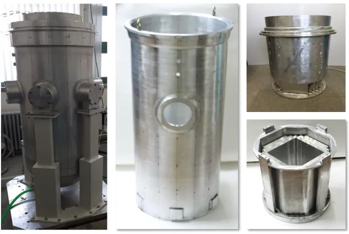
considering the spacing between the structures for the sensors to enter. Supports, RVIs and base are bolted like real boundary conditions. Scaled-down model was constructed as shown in Figure 2.
Figure 1. Configuration of scaled-down model.
Figure 2. Manufacture of scaled-down model [9].
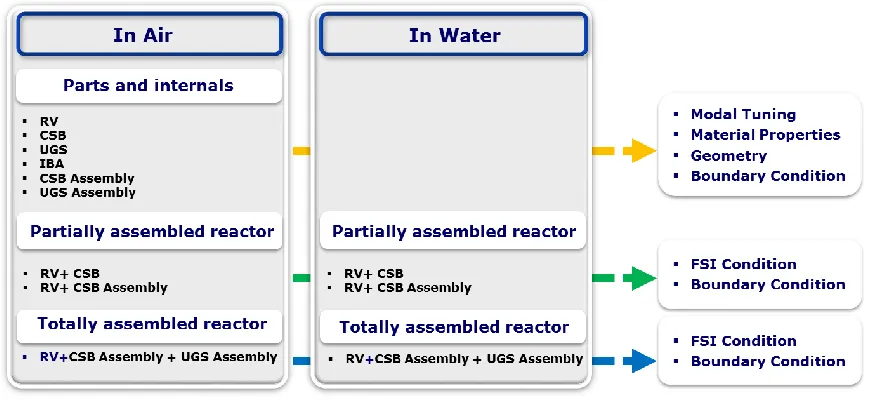
Experiment Procedure and Setup
accuracy in the selected structural units. Single structure experiments were carried out with a modal test using an impact hammer and an accelerometer under free-free conditions using an elastic support. Through these experiments, the appropriateness of material properties and geometry required for FE model construction of each structure is ensured. The experimental results of the assemblies were the basis for simulating the boundary conditions between the assemblies when constructing the FE model.
Figure 3. Experiment procedure.
It is important for the FE model to accurately reflect the boundary condition between the reactor vessel and each internal assembly to the FE model because the reactor vessel and the internal structures are built based on the reactor vessel. For the assembly conditions between the CSB assembly and the reactor vessel, the outer flange of the CSB is placed on the flange of the reactor vessel, which is important because it is the main boundary condition for determining the dynamic characteristics of the assembled reactor. The coupling conditions with reactor vessel for CSB and CSB assembly were respectively tested and the dynamic characteristics data required to describe the above boundary conditions were obtained in the FE model construction. For the same reason, the whole assembly condition with the UGS assembly added to the above assembling condition was tested and the basic data for describing the boundary condition between the structures was obtained.
Fluid-structure interaction by coolant is a factor that influences the dynamic characteristics of reactor vessels and internal structures as well as assembling boundary conditions between structures.
Therefore, the experiment including the coolant replaced with water was carried out, and the change of the dynamics of the structure due to the fluid-structure interaction effect was confirmed. The experimental results are the reference data for accurately describing the fluid-structure interaction in the FE model construction.
FE Model Construction Based on Experimental Results
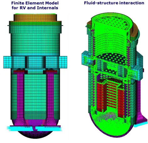
Based on the reference data obtained from the air and water experiments, finite element analysis model of totally assembled reactor was constructed as shown in Figure 5. The boundary condition between the reactor vessel and the CSB assembly flange was created through node merging. Experiments were carried out to control the number of merged nodes with respect to the reference data, so that they had the same dynamic characteristics as the experiment. The boundary conditions of the hold down ring, UGS Assembly, and RV cover placed on the CSB Assembly were also controlled by the node merging method and the merging number. Fluid-structure interaction conditions are also shown in Figure 5, in which the interaction effects and the additional mass effects are applied by coupling the degrees of freedom in the vertical direction at the interface of the structure according to the characteristics of the Fluid80 element, which is the displacement-based element.
In the previous study, the dynamic characteristics of the reactor vessel and internal structure based on the experimental results were investigated with the above boundary conditions. Also, through the similarity analysis, the validity of the finite element analysis model and the experimental data was verified [8].
Figure 4. FE model for totally assembled reactor.
Modification of Boundary Condition for Earthquake Response Analysis
This section describes the boundary conditions of the actual reactor vessel and internal structures that are not reflected in the scaled-down model. As can be seen in Figure 6, the three boundary conditions, the shear key between RV and support column, the snubber between CSB and RV and the guide lug between FAP and CS were not reflected in the scaled-down model that is the basis of this study. These boundary conditions are designed to prevent excessive behavior against earthquake, fluid induced vibrations or other external forces in actual reactor structures.
contact occurs, in experiments, it is impossible to conduct the experimental modal analysis because the impact caused by the contact is additionally input to the structure. For the above two reasons, the scaled-down model did not reflect the three boundary conditions. Therefore, this study additionally reflected the boundary conditions only in the analytical model.
Figure 5. Reflected boundary conditions for seismic analysis.
As described in the previous paragraph, boundary conditions that are not reflected have gaps. Therefore, contact due to vibration displacement occurs in the seismic analysis which is the final goal of this study. Therefore, it is an accurate method to analyze the seismic response by applying the contact analysis technique. However, since the finite element model itself has many elements and the fluid-structure interaction condition, the analysis cost is very large. If the contact analysis which is nonlinear analysis is added, the analysis cost increases exponentially and the analysis becomes almost impossible. Therefore, in this study, it is applied to the finite element model by replacing contact boundary conditions with equivalent boundary conditions. The boundary condition is DOF coupling. These approximate method is effective because the gaps in the actual reactor are very small compared to the structure size, and the gaps of the structure due to the high temperature generated during the operation of the reactor becomes nearly zero. The changes exist in the dynamic characteristics of the reactor vessel and internal structures before and after the boundary condition was reflected. As mentioned in previous studies, Since the RV bending modes and CSB bending modes with out-of-plane have large effective mass as well as the frequencies of these modes in the main seismic frequency band of 1 to 10 Hz, It was expected to be the main mode of response of the structure [8],[10]. In the subsequent studies, it was shown that these modes are the main response modes of the reactor vessel and internals in the results of the time history seismic analysis [11].
As shown in Figure 8, these major modes were significantly changed in natural frequency and mode shape after modifying boundary conditions. The CSB bending modes with out-of-plane, where the effective mass was the largest mode, disappeared due to the constraints of the CSB snubber conditions. Not only was there a small change in the RV bending modes shape due to the CSB snubber and RV shear key conditions, but the frequency was also reduced by 20 % and 30 %, respectively, due to the contribution of the mass of the fuel bound to the CSB and the increase in the stiffness of RV lower part. As a result, RV bending modes have the effective mass corresponding to about 93 % of the total effective mass. Also, these changes support that the RV bending modes in the seismic response analysis mentioned in the next section are the main behavior of reactor vessels and internal structures.
Seismic Response Analysis with using model reduction technique
The FE model based on the experimental dynamics results using the scaled-down model and modified the boundary conditions is composed of about seventy-six million elements and two million equations. The large number of elements as well as the fluid-structure interaction condition make the analysis cost large. This high analysis load causes a lot of analysis capacity and time in seismic time history analysis, which is obtaining seismic response in the time domain. In previous studies, an effective vibration analysis model was constructed by reducing the number of degrees of freedom by applying the model reduction method to solve these problems [10]. Based on that, seismic response analysis was also conducted [11]. However, the boundary conditions for preventing excessive vibration described in the previous section are missing, and as a result, they have different seismic responses, so a new interpretation is needed. In this study, the seismic response analysis was performed with the FE model constructed to reflect the boundary conditions mentioned in the previous section to obtain accurate responses. In order to perform efficient analysis by lowering the analysis load, seismic response analysis was performed using the component mode synthesis (CMS) [11].
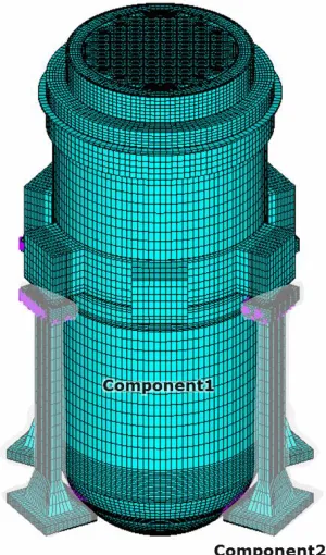
Based on the results of previous studies, the fixed interface method was selected among the CMS methods [11]. Considering the reactor vessel and internal structures as one component not only reduces the overall model size by modal truncation but also shows high accuracy and efficiency within the frequency ranges. Therefore, as shown in Figure. 7, it is an adopted method that the whole model is divided into two components. One component is the reactor vessel and internal structures, and the other component is the RV shear key and support column. All the DOFs of the nodes at the interface between the reactor vessel and the support column and the hemispherical interface where the shear key is separated were selected as the master degree of freedom (MDOF).
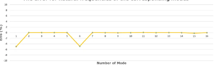
Figure 8. Errors of natural frequencies between CMS model analysis and full model analysis.
To verify the validity of the future seismic time history analysis, the dynamic characteristics of the CMS model were compared the dynamic characteristics with those of the full model. The verification was conducted via modal and harmonic analysis. In order to compare the modal analysis results, the error of the natural frequency between the corresponding modes of the full model and the CMS model was obtained. As shown in Figure 8, not only the error rate is less than 5%, but also the harmonic analysis result shows that the absolute value of the error is within 7%. The reduction of analysis cost, which is a major reason for applying the model reduction method, has increased approximately 3 times in modal analysis and decreased approximately 20 times in harmonic analysis. The model reduction method is divided into three parts: generation pass, use pass, and expansion pass. The generation pass generates super elements by reducing the order of the entire model by the number of MDOFs selected. The use pass performs vibration analysis such as modal, harmonic, and time history analysis which solves equations having reduced order of the generated super elements. The expansion pass recomputes the response values of the entire DOF through back-substitution using the calculated response of MDOF. The reason for the increase in the analysis cost of the modal analysis is that the load generated when the model is reduced in the generation pass is more expensive than the full analysis. However, as can be seen from the results of the harmonic analysis cost, the CMS model has a great effect when the analysis cost corresponding to the use pass is large.Therefore, it is expected that the CMS model has a great effect on the cost reduction by applying the CMS model to the case of time history analysis which has a larger calculation load than the load for constructing the equation.
Using the CMS method application model, the seismic time history analysis was conducted with using the large mass method. The input acceleration data of the El-centro earthquake with 0.3 g was applied to the large mass (LMM). The large mass has a mass equivalent to 100,000 times the reactor vessel and internal structures including the support. Large mass and DOFs at the bottom of the RV support column are connected to allow the acceleration of earthquakes to be transferred from the large mass to the reactor structure. As mentioned in the previous section, consequently, the RV bending modes with large effective mass dominate the overall seismic response. The top flange of RV showed a large moving behavior, resulting in a maximum displacement in the top flange of RV.
where the maximum displacement occurs is also important because the mass of the fuel occupies most of the mass of the entire structure. Since the fuel is assembled through the LSS at the bottom of the CSB, it is necessary to check the contact between the CSB snubber and the stabilization lug of the RV. The relative displacement of the snubber and the stabilization lug is about 0.07 mm. The contact does not occur considering that the gap between the two parts is 0.165 mm.
Figure 9. Time historical displacement at top flange of RV.
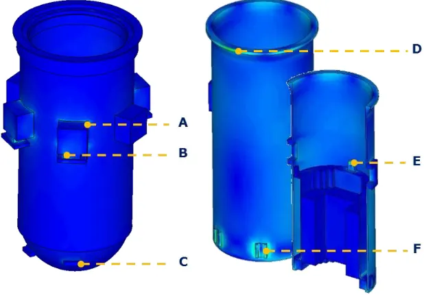
In order to evaluate the structural integrity, stress response of each structure was confirmed as well as displacement. Since dominant behavior is RV bending modes and nuclear fuel is assembled in the CSB, large stresses occur in RV and CSB compared to other structures. Figure 10 shows the location of the stress values in Table 1. In the case of RV, since RV bending modes are bending based on the lower end fixed with the RV with the support, large stress is generated in the outlet part where the support and RV are assembled. The maximum stress occurred at the plate between the outlet and the support. In case of CSB, relatively high stress was observed at the assembly boundary, similar to the case of RV, and maximum stress occurred in CSB flange assembled with RV.
As a result, relatively high stresses occurred at the assembly boundary compared to the entire structure. The reason is related not only to the major behavior of the structure in seismic response but also to the stress concentration due to the shape. The geometric shape of the FE model used in this study is based not only on the scaled-down model but also as a partial simplification model. For these reasons some parts have changed dramatically in geometrical shape. For example, at the intersection of let and RV, the curve and plane meet. Shear keys or snubber parts also change shape in part due to the same reason. Stress concentration occurs at such a geometrically changed parts, resulting in a stress having a greater stress than the actual value. Therefore, the stress values in Table 1 are somewhat overestimated.
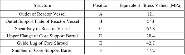
Table 1: Stress values at the specific points.
Structure Position Equivalent Stress Values [MPa]
Outlet of Reactor Vessel A 121
Outlet Support Plate of Reactor Vessel B 543
Shear Key of Reactor Vessel C 67.8
Upper Flange of Core Support Barrel D 28.4
Guide Lug of Core Shroud E 42.7
Snubber of Core Support Barrel F 47.2
CONCLUSION
In this study, the following points were emphasized.
- To ensure the validity of the FE model, a scaled-down model was constructed and the dynamic characteristics experiment was conducted.
- The FE model with the same dynamic characteristics as those obtained from the scaled-down model was constructed.
- The critical boundary conditions for seismic response analysis were modified and applied to the FE model as equivalent boundary conditions.
- For accurate response, time history analysis was performed. In order to reduce the analysis cost, CMS which is one of model reduction method and suitable for the modified FE model was developed and applied.
- The time-history dynamic responses and stresses for the reactor vessel and internals for the El-centro earthquake were calculated.
Finally, although the dynamic responses and stresses were calculated more precisely than in the previous studies, the stress in the parts of the FE model where the sudden geometric change exists was some extent exaggerated due to the stress concentration. Therefore, in future research, more accurate stress evaluation will be conducted through submodeling technique which can partially recalculate stress.
REFERENCES
[1] Chen SS, Rosenberg GS (1975). “Dynamics of a coupled shell fluid system”, Nuclear Engineering and Design, 32 302–310.
[2] Horácek J, Trnka J, Veselý J, et al (1995). “Vibration analysis of cylindrical shells in contact with an annular fluid region”, Engineering Structures, 17 714–724.
[3] Jeong KH (1998). “Natural frequencies and mode shapes of two coaxial cylindrical shells coupled with bounded fluid”, Journal of Sound and Vibration, 215 105–124.
[5] Sigrist JF, Daniel DB, Lainé C (2007). “Dynamic analysis of a nuclear reactor with fluid-structure interaction: part I: seismic loading, fluid added mass and added stiffness effects”, Nuclear Engineering and Technology, 236 2431–2443
[6] Frano RL, Forasassi G (2009). “Conceptual evaluation of fluid structure interaction effects coupled to a seismic event in an innovative liquid metal nuclear reactor”, Nuclear Engineering and Design, 239 2333–2342.
[7] Young Jin Byun, Jung Gyu Kim, Ki Kwang Sung, Dae Hee Lee (2015). “An Investigation of Major Influences on the Seismic Response of APR1400 Reactor Vessel Internals”, Proceedings of ICAPP
2015, Paper 15145.
[8] Park JB, Choi Y, Lee SJ, et al (2014). “Modal characteristic analysis of the APR1400 nuclear reactor internals for seismic analysis”, Nuclear Engineering and Technology, 46 689-698.
[9] Jong-beom Park, Sang-Jeong Lee, Young-Pil Park, Youngin Choi, et al (2017). “Seismic analysis of the APR1400 nuclear reactor system using a verified beam element model”, Nuclear Engineering and Design, 313 108-117.