CORE® 8
System
Copyright © 2007-2011 Vitech Corporation. All rights reserved.
No part of this document may be reproduced in any form, including, but not limited to, photocopying, translating into another language, or storage in a data retrieval system, without prior written consent of Vitech Corporation.
Restricted Rights Legend
Use, duplication, or disclosure by the Government is subject to restrictions as set forth in subparagraph (c) (1) (ii) of the Rights in Technical Data and Computer Software clause at DFARS 252.277-7013.
Vitech Corporation
2270 Kraft Drive, Suite 1600 Blacksburg, Virginia 24060 540.951.3322 FAX: 540.951.8222 Customer Support: [email protected]
www.vitechcorp.com
CORE® is a registered trademark of Vitech Corporation.
Other product names mentioned herein are used for identification purposes only, and may be trademarks of their respective companies.
CONTENTS
PREFACE ... vi
1 REQUIREMENTS CAPTURE ... 1
1.1 Define Need and System Concept ... 1
1.2 Capture Source (Originating) Requirements ... 1
1.3 Define System Boundary ... 5
1.4 Collect Additional Applicable Documents ... 7
2 REQUIREMENTS ANALYSIS ... 9
2.1 Parse Originating Requirements ... 9
2.2 Identify Requirement Concerns and Risks ... 9
2.3 Characterize Requirements and Categorize Constraints ... 13
3 FUNCTIONAL ANALYSIS ... 17
3.1 Identify States/Modes (If Needed) ... 17
3.2 Use Cases (If Needed) ... 18
3.3 Develop the System Functional Hierarchy ... 21
3.4 Refine and Allocate Functional Performance Requirements ... 24
3.5 Capture Functional and Performance Concerns and Risks ... 25
4 PHYSICAL ARCHITECTURE SYNTHESIS ... 29
4.1 Allocate Functions to Next Level of Components ... 29
4.2 Refine External Interface Definitions... 30
4.3 Derive or Refine Internal Interfaces ... 33
4.4 Assign/Derive Constraints for Components ... 35
4.5 Capture Physical Architecture Concerns and Risks ... 36
5 VERIFICATION/VALIDATION ... 39
5.1 COREsim... 39
5.2 Establish Verification Requirements ... 39
5.3 Establish Verification Events and Test Procedures... 40
5.4 Test Planning ... 41
6 CHANGE MANAGEMENT SUPPORT ... 45
LIST OF FIGURES
Figure 1 Systems Engineering Activities ... vi
Figure 2 Source Requirements ... 3
Figure 3 System Boundary ... 6
Figure 4 Applicable Documents and Requirements ... 7
Figure 5 Derived Requirements ... 9
Figure 6 Requirement Concern and Risk ... 10
Figure 7 Constraint Requirements ... 14
Figure 8 States and Modes ... 17
Figure 9 Use Case Application ... 19
Figure 10 Functional Decomposition ... 22
Figure 11 Performance Requirements ... 24
Figure 12 Functional or Performance Requirement Concern and Risk ... 25
Figure 13 Component Hierarchy and Function Allocation ... 29
Figure 14 External Interface Definition ... 31
Figure 15 Internal Interface Definition ... 33
Figure 16 Component Constraint Requirements ... 35
Figure 17 Physical Architecture Concern and Risk ... 36
Figure 18 Verification Requirements ... 39
Figure 19 Verification Planning and Tracking ... 40
Figure 20 Test Planning ... 42
Figure 21 Change Management Support ... 45
LIST OF TABLES
Table 1 System Definition ... 1
Table 2 Source Requirements ... 3
Table 3 System Boundary ... 6
Table 4 Applicable Documents and Requirements ... 8
Table 5 Derived Requirements ... 9
Table 6 Requirement Concern and Risk ... 11
Table 7 Constraint Requirements... 15
Table 8 States and Modes ... 18
Table 9 Use Case Application ... 20
Table 10 Functional Decomposition ... 22
Table 11 Performance Requirements ... 24
Table 12 Functional or Performance Requirement Concern and Risk ... 25
Table 13 Component Hierarchy and Function Allocation ... 30
Table 14 External Interface Definition ... 32
Table 15 Internal Interface Definition ... 34
Table 16 Component Constraint Requirements ... 35
Table 17 Physical Architecture Concern and Risk ... 37
Table 18 Verification Requirements ... 40
Table 19 Verification Planning and Tracking ... 41
Table 20 Test Planning ... 43
Table 21 Change Management Support ... 46
PREFACE
This guide provides a structured approach to populating a CORE project with systems engineering information using the basic schema provided with CORE. It presents actions that must be accomplished in the context of the classic systems engineering activities of requirements analysis, functional analysis, physical architecture synthesis, and verification and validation as illustrated in Figure 1. Thus, the approach is consistent with commonly used systems engineering handbooks and standards, company unique Capability Maturity Model® Integration (CMMI) processes, and project specific Systems Engineering Plans (SEP) and Systems Engineering Management Plans (SEMP).
Figure 1 Systems Engineering Activities
Each activity and the CORE schema classes used to capture the associated information in the repository are described. A schema diagram and table identifying the schema classes to be used and the attributes and relationships that should be established when performing the activity follow each activity discussion. In addressing each activity, attention is given to populating the repository in a manner that facilitates the production of formal documents using the standard scripts provided with CORE. This guide describes the development of a system design that results in standard documentation at minimal additional cost.
the training class and make the most effective use of CORE on a project. The approach is generic and is not exhaustive of all cases and situations. The approach is written in the context of top-down systems engineering. The activities can be reordered for middle-out or reverse engineering.
The following additional resources are available for use with this guide:
For descriptions of different views, behavior diagram notation, and the mechanics of entering data into CORE, the reader is referred to the CORE on-line help.
For the definition of schema terms, the reader is referred to the CORE schema, which contains descriptions for each schema entity and to the Schema Definition Report script, which outputs documentation of the schema definition for a selected facility.
For details on generating standard formal documents, the reader is referred to the script help file for the formal documentation scripts. By selecting the Run Script icon on the CORE Explorer toolbar and then selecting any one of the formal documentation scripts such as the System/Segment Specification (SSS), and then pressing the Script Help File button will open this documentation.
1
REQUIREMENTS CAPTURE
This section is written assuming that the end-user has been provided with a system requirements specification. If that is not the case, it is assumed that systems engineering will start with the task of collecting all stakeholder needs and transforming them into required functionality and performance and design constraints. The end result of this effort will be a collection of requirements that are treated as originating requirements (See Section 1.2).
1.1
Define Need and System Concept
Identify the system and its mission. Physical entities, including the system, external systems, and entities within the system (excluding interfaces) are represented in CORE as elements in the class Component. When creating the Component that represents the system, the attributes listed in Table 1 should be assigned values. A Component’s Type attribute designates what the element represents (in this case a System). The relationships and target classes are established in subsequent sections.
Table 1 System Definition
Element Class Attributes Relationships Target Classes
Component Abbreviation Description Doc. PUID Mission Number Purpose Type: System
1.2
Capture Source (Originating) Requirements
Capturing requirements from source documents involves the creation in the repository the following:
Document element for each source document
Requirement element for each source requirement
ExternalFile element for each source requirement-related table or graphic
DefinedTerm element for each pertinent acronym or special term in the source requirements
Parse compound requirements into single, testable Requirements statements. These should be linked to their parent Requirement using the refines/refined by
relationship.
Place any requirements tables and graphics in separate files and reference them in the project repository using ExternalFile elements where each augments the subject
Requirement. The formal documentation scripts, as well as the System Description Document (SDD) script, will automatically include these external tables and graphics in the output immediately following the element Description and make entries in the List of Figures and List of Tables, as appropriate. In order to properly number and label the tables and graphics for inclusion in the output, only a single graphic or table should appear in each file.
Acronyms and/or special terms appearing in the source document should be captured in the repository as DefinedTerms. For an acronym or abbreviation, the acronym is entered into the Acronym attribute and what it stands for is entered as the name of the element. For a special term, the term is the name of the element and its definition is entered into the Description attribute. By filling in both the Acronym and Description attributes, appropriate entries will appear in both the acronym and glossary sections of documents generated using the CORE formal documentation scripts once the DefinedTerm is linked to the output Document
using the used by relationship.
The following paragraphs contain information on special topics concerning the entry of source requirements.
Extracting requirements from source documents. The entry of source requirements into a CORE repository may be accomplished by using one or more of the following:
Element Extractor
Document/Shall Parser script
Advanced CSV File Parser script if the requirements are being transferred as a CSV file from another application such as IBM® DOORS, Microsoft Excel, or Microsoft Access
Copy and Paste or Paste Unformatted commands.
Setting the Origin attribute. It is important to determine the customer’s acceptable requirements traceability. A customer may require traceability to the exact wording in a source document or may allow traceability to parsed statements. Once this decision has been made; set the Origin attribute to Originating for each Requirement in the document requirements hierarchy down through the lowest-level traceable
Requirements (i.e., those deemed originating by the customer). For all other
record which Requirements are originating and ensure that the traceability matrix produced by the CORE formal documentation scripts traces to the correct source
Requirement elements.
Establishing Doc. PUIDs. If the source documents have assigned Project-Unique Identifiers (PUIDs) to the requirements, these should be captured in the repository in the Doc. PUIDattribute of the Requirement. If PUIDs have not been pre-assigned, it is advisable to assign one to each originating Requirement. This can be done manually or by running the Assign Documentation PUID utility script.
Note: If available, Doc. PUIDs are automatically output by all of the formal documentation scripts. To take advantage of this feature, Doc. PUIDs should be assigned to elements in the following classes: Component, Function, Interface, Item, Link,
Requirement, and VerificationRequirement.
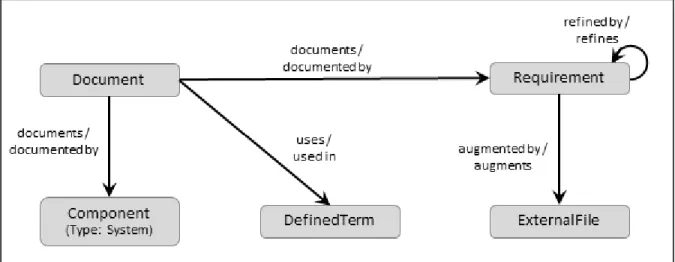
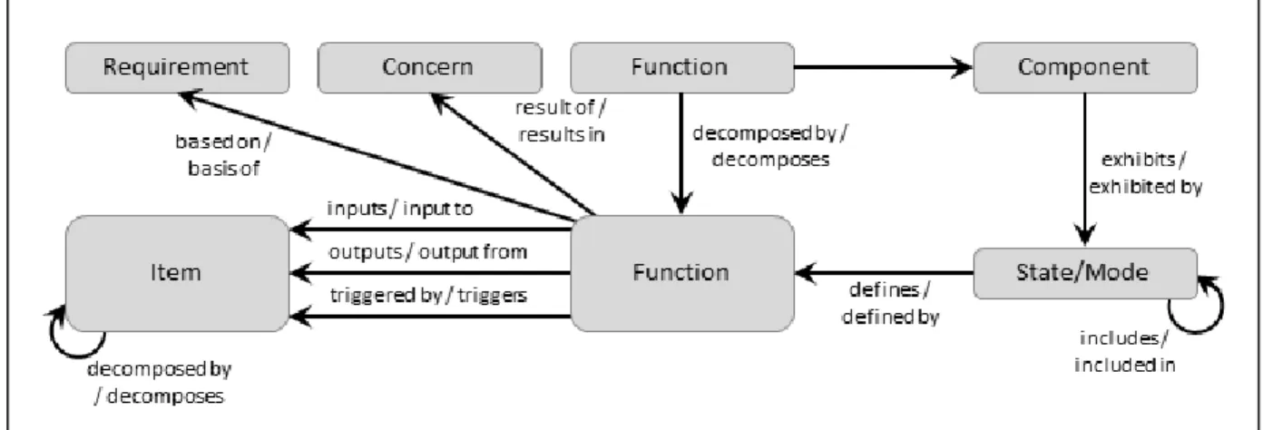
Figure 2 Source Requirements Table 2 Source Requirements
Element Class Attributes Relationships Target Classes
DefinedTerm Acronym
Description
used in / uses Document
Document CDRL Number Description Document Date documents / documented by2 Component (Type: System) Requirement
2
Only the top-level Requirements need to be documented by the source Document. The formal documentation scripts search up the requirements hierarchy to locate the source Document.
Table 2 Source Requirements
Element Class Attributes Relationships Target Classes
Document Number External File Path either1 Govt. Category or Non-Govt. Category Number Type
uses / used in DefinedTerm
ExternalFile Description
External File Path Number Page Orientation Title Type augments / augmented by3 Requirement Requirement Description Doc. PUID Incentive Performance Parameter Key Performance Parameter Number Origin: Originating Paragraph Number4 Paragraph Title4 Rationale Units Value Weight Factor augmented by / augments3 ExternalFile documented by / documents Document
refined by / refines Requirement
refines / refined by Requirement
1
These attributes are used when the source document is to be listed as an applicable document in a formal document generated from the repository. See Section 1.4 for an explanation.
3
The Position attribute of this relationship should be set to control the order in which multiple external files are appended to the Requirement’s Description attribute when it is output in formal documentation generated from the repository.
Warning: The default font for text attributes, such as Description, is Times New Roman 10. Within a text attribute, the user has control over color, fonts, styling, sizing, and special effects such as underline, superscript, and strikethrough. The formal documentation scripts do not override any user modified fonts or special effects; however, they can override color, styling, and font size if the font is Times New Roman (they only control the styling of text in Times New Roman). Consequently, in order to produce professional looking documents, care should be taken when capturing external source material. Specifically, when using the Element Extractor window, either turn off the Maintain Formatting option or pre-process the document to convert all text to Times New Roman (i.e., open the document in a word processor, select all contents of the document, and select Times New Roman as the font). Similarly, when using cut & paste, either pre-process the document to set the font to Times New Roman or use Paste Unformatted rather than the Paste command. Since they should not be modified on output, formulas should be captured in another font, such as Arial. Also, note that text attributes do not support embedded tables and graphics. Therefore, tables and graphics should be captured as ExternalFile elements.
1.3
Define System Boundary
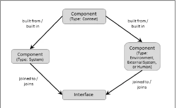
Based on an examination of the originating requirements, identify the system boundary and context. To define the boundary, identify each external with which the system must interface. An external is represented as a Component and may identify the system environment, an actual external system, or a human. Create a Component element representing the context and decompose it into the system and its externals using the
built from relationship. Set the Type attribute for each Component. Note that humans may be considered as part of the system or as external to the system depending on the actions they take or the role that they play in performing the system actions. In many cases, there are humans that are part of the system and humans that are external to the system.
To complete the system boundary definition, identify all interfaces between the system and each external by creating elements of the Interface class. Defining an Interface
element establishes that the system interacts with an external. Typically, there will be only one interface between the system and each external. The details of the interface are documented by Link elements (See Section 4.2).
Figure 3 System Boundary Table 3 System Boundary
Element Class Attributes Relationships Target Classes
Component
(Type: Context)
Description Number Type: Context
built from / built in Component
(Type: System and Environment, External System, or Human) Component (Type: Environment, External System, or Human) Abbreviation Description Number Type: Environment, External System, or Human
built in / built from Component
(Type: Context)
joined to / joins Interface
Component
(Type: System)
See Section 1.1 built in / built from Component
(Type: Context)
joined to / joins Interface
Interface Description
Doc. PUID Number
joins / joined to Component
(Type: System and Environment, External System, or
Suggestion:Create a folder for the context and externals in order to separate them from the evolving system component hierarchy. Typically, the context and externals are given a different numbering scheme than the elements in the system component hierarchy in order to differentiate them in CORE views such as the Physical Block Diagram and Hierarchy diagrams.
1.4
Collect Additional Applicable Documents
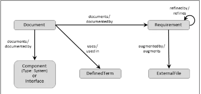
Identify any other applicable or reference documents such as standards, regulatory documents, and Interface Control Documents for interfaces to existing external systems. These or specific portions of these documents may be referenced in the source requirements. If a reference is not sufficient, extract additional Requirements from the applicable or reference documents.
Note: The applicable documents will eventually be linked to other Document elements that represent the formal documents generated from the repository. The formal documentation scripts will automatically include the references to applicable documents in Section 2 of the produced specification or design document once these relationships are established. In order for an applicable document to appear in the correct subsection, either the Govt. Category or the Non-Govt. Category attribute must be set to the appropriate subsection heading.
Table 4 Applicable Documents and Requirements
Element Class Attributes Relationships Target Classes
DefinedTerm See Section 1.2 used in / uses Document
Document See Section 1.2 documents /
documented by
Component Interface Requirement
uses / used in DefinedTerm
ExternalFile See Section 1.2 augments /
augmented by5
Requirement
Interface See Section 1.3 documented by /
documents
Document
Requirement See Section 1.2 augmented by /
augments5
ExternalFile
documented by / documents
Document
refined by / refines Requirement
refines / refined by Requirement
Suggestion: Create folders to group source documents and applicable documents. An element, such as a Document, may appear in multiple folders. To remove an element from a folder, drag it to another folder. Deleting an element removes the element from the repository.
5
2
REQUIREMENTS ANALYSIS
Requirements analysis involves a collection of concurrent, inter-related activities. These are addressed in the following subsections.
2.1
Parse Originating Requirements
If not previously done when capturing source requirements (See Section 1.2), parse the originating Requirements into single, testable Requirements statements. This parsing can result in concerns to be resolved. These should be identified as described in Section 2.2 below. See Section 1.2 for a discussion of Originating vs. Derived Requirements.
Figure 5 Derived Requirements Table 5 Derived Requirements
Element Class Attributes Relationships Target Classes
Requirement Description Doc. PUID Number Origin: Derived Rationale Weight Factor
refined by / refines Requirement
refines / refined by Requirement
2.2
Identify Requirement Concerns and Risks
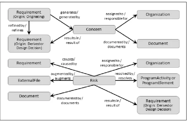
Requirement Concerns. Examine each parsed source Requirement, capturing any questions or problems identified by creating Concern elements. The assignment of resolution responsibility to an individual or organization is captured by the assigned to
relationship between the Concern and an Organization element. The resolution of a
captured in the repository using the Document element and linked to the Concern using the documented by relation. The resolution of a Concern is not a requirement but generally either results in a derived or design decision Requirement, or the addition or clarification of Requirements. Any resultant Requirement (Origin set to Design Decision) should be linked to both the Concern and the Requirement(s) that generated the
Concern.
Requirement Risks. Risks are concerns that are significant enough to potentially affect the achievement of a major program objective or milestone. Because the information needed is different than that of a Concern, Risk is a separate element class in CORE. Among the many sources of risk on a program, one of these is the requirements themselves. Therefore, examine each leaf-level source Requirement and identify any
Risks. This may be done by the systems engineers or risk management personnel depending on the project organization. Generally, Risks are addressed by a
ProgramActivity or ProgramElement in the Program Management Facility. Details of program management are not addressed in this guide. In addition, Risks may result in
new Requirements. Any risk status graphs should be identified as ExternalFiles and linked to the Risk using the augments relationship. Similarly, any risk status reports should be identified as Documents and linked to the Risk using the documents
relationship.
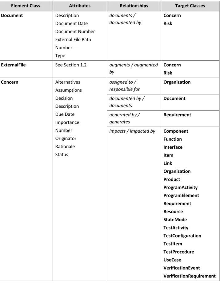
Table 6 Requirement Concern and Risk
Element Class Attributes Relationships Target Classes
Document Description
Document Date Document Number External File Path Number Type documents / documented by Concern Risk
ExternalFile See Section 1.2 augments / augmented
by Concern Risk Concern Alternatives Assumptions Decision Description Due Date Importance Number Originator Rationale Status assigned to / responsible for Organization documented by / documents Document generated by / generates Requirement
impacts / impacted by Component Function Interface Item Link Organization Product ProgramActivity ProgramElement Requirement Resource StateMode TestActivity TestConfiguration TestItem TestProcedure UseCase VerificationEvent VerificationRequirement
Table 6 Requirement Concern and Risk
Element Class Attributes Relationships Target Classes
results in / result of Requirement
Organization Abbreviation Description Number Role responsible for / assigned to Concern Risk ProgramActivity Description End Date Number Start Date
resolves / resolved by Risk
ProgramElement Contract Number
Cost Description End Date Labor Hours Non-recurring Cost Start Date Type
resolves / resolved by Risk
Requirement See Sections 1.2 and
2.1
causes / caused by Risk
generates / generated by
Concern
refined by / refines Requirement
refines / refined by Requirement
result of / results in Concern Risk Risk Consequences Description Impact Likelihood Mitigation Plan Risk Effective Date Risk Factor assigned to / responsible for Organization augmented by / augments ExternalFile
caused by / causes Requirement
documented by/ documents
Table 6 Requirement Concern and Risk
Element Class Attributes Relationships Target Classes
Status
Status Description Type
impacts / impacted by Component Function Interface Item Link Organization Product ProgramActivity ProgramElement Requirement Resource StateMode TestActivity TestConfiguration TestItem TestProcedure UseCase VerificationEvent VerificationRequirement
resolved by / resolves ProgramActivity ProgramElement
results in / result of Requirement
2.3
Characterize Requirements and Categorize Constraints
Requirements can be characterized as one of the following:
Constraint (i.e., limitation on the design or construction of the system)
Functional (i.e., what the system must do)
Incentive Award Fee Criterion (i.e., programmatic or other requirements affecting a contractor’s fees for meeting or exceeding the requirement)
Performance (i.e., how well the system or function must perform)
Test (i.e., test constraints)
Verification (i.e., acceptance criteria).
This aspect of a requirement is captured in the repository by setting the Requirement's
Type attribute to the appropriate value. If a determination cannot be made, parse the
Requirement into a set of Requirements where each Requirement is only one of the seven types.
Link the system-level constraint Requirements to the system Component using the
specifies relationship. As the system component hierarchy evolves, a constraint
Requirement should be linked to all of the Components to which it applies (i.e., a constraint Requirement may apply to the descendants of a Component as well as the
Component). See Section 4.4 for a discussion of constraints on lower-level Components
and constraint hierarchies.
Constraint Categorization. For each Requirement that is a constraint, categorize it by a
Category that represents the appropriate requirements domain, such as Reliability, Transportability, Electromagnetic Radiation, etc. These domains correspond to the non-functional leaf-level requirements sections typically found in a System/Segment Specification or other specification. For the standard formal documents supported by CORE, these Categories have been pre-defined in the Document Template XML file provided with CORE. The templates are located in the Reports\Formal Documentation\Document Templates folder and should be imported into the repository to obtain the suggested specification outlines (i.e., Documents and Sections), and associated ReportScripts and Category elements. See the formal documentation scripts help file for further information.
Note: As further explained in the formal documentation script help file, Categories and the specification outlines should remain synchronized. Categories may be hierarchical; in which case, the hierarchy will control the definition of lower-level Sections in the formal documents. When using category hierarchies, only the leaf-level Categories should
categorize requirements.
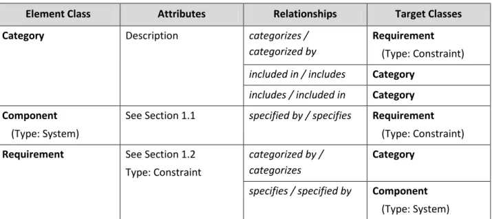
Table 7 Constraint Requirements
Element Class Attributes Relationships Target Classes
Category Description categorizes /
categorized by
Requirement
(Type: Constraint)
included in / includes Category
includes / included in Category Component
(Type: System)
See Section 1.1 specified by / specifies Requirement
(Type: Constraint)
Requirement See Section 1.2
Type: Constraint
categorized by / categorizes
Category
specifies / specified by Component
3
FUNCTIONAL ANALYSIS
3.1
Identify States/Modes (If Needed)
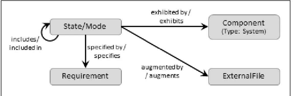
On some projects, either the customer expects or it is desirable from a documentation point of view to organize Functions by states and/or modes. Identify any states and/or modes of the system using State/Mode elements. Since states and/or modes could be used in the Component hierarchy at other than the system level and Functions will be mapped to States/Modes (See Section 3.2), separate State/Mode hierarchies need to be defined for each Component needing a state/mode representation. The Title attribute allows the formal documentation reference names to be the same for different
State/Mode elements. A State/Mode can be specified by a Requirement. A state/mode transition diagram can be referenced in the repository by creating an ExternalFile
element that augments a State/Mode element.
Note: Some organizations identify phases of operations of the system rather than states/modes. In this case, it is recommended that the State/Mode class be used to identify the phases and that the State/Mode class name be aliased to Phase.
Table 8 States and Modes
Element Class Attributes Relationships Target Classes
Component
(Type: System)
See Section 1.1 exhibits / exhibited by6 State/Mode
ExternalFile See Section 1.2 augments /
augmented by7
State/Mode
Requirement See Sections 1.2, 2.1,
and 2.3
specifies / specified by State/Mode
State/Mode Description Number Title Type augmented by / augments7 ExternalFile
exhibited by / exhibits6 Component
included in / includes State/Mode
includes / included in State/Mode
specified by / specifies Requirement
3.2
Use Cases (If Needed)
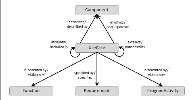
On some projects, use cases are used instead of threads or scenarios. In other instances, use cases are precursors to the development of threads or scenarios, which are extremely useful for gaining insight into the behavior of the system and lead to developing the integrated behavior of the system. Identify any system use cases using
UseCase elements. A UseCase element describes a Component to which the use case is applicable. A UseCase element involves a Component fulfilling the role of an actor in the use case. A UseCase element is elaborated by either a Function element, a
ProgramActivity element or a TestActivity depending upon whether the use case affects a system behavior, program management behavior or test behavior. A UseCase
element can be extended by a UseCase to add additional specificity to the use case. A
UseCase element can be specified by a Requirement. An external use case diagram can be referenced in the repository by creating an ExternalFile element that augments a
UseCase element.
6
A component should link only to the top elements of a state/mode hierarchy. The formal documentation scripts will automatically include the entire state/mode hierarchy for the associated component.
7
Table 9 Use Case Application
Element Class Attributes Relationships Target Classes
Component See Section 1.1 described by / describes UseCase
ExternalFile See Section 1.2 augments /
augmented by8
UseCase
Requirement See Sections 1.2, 2.1,
and 2.3
specifies / specified by UseCase
UseCase Alternate Flow
Description Number Postconditions Preconditions Primary Flow augmented by / augments7 ExternalFile based on / basis of Requirement describes/ described by Component elaborated by/ elaborates Function ProgramActivity TestActivity extends/ extended by UseCase
impacted by / impacts ChangeRequestPackage Concern Risk includes/ included in UseCase involves/ participates in Component
8
3.3
Develop the System Functional Hierarchy
Functional analysis in CORE begins with defining major threads through the system and culminates in an integrated behavior view of the system and subcomponent actions. For the system, a top-level Function should be defined and allocated to the Component of type system. The allocated to relationship attribute Behavior Type should be set to “Integrated (Root)” in order to identify that this top-level Function represents the totality of functionality performed by the system and is decomposed (hierarchically) into all of the functions performed by the system. The root Function is decomposed into the primary Functions of the system. Upon establishing new component, CORE will automatically create a new Function element, establishes the performs / allocated to
relationship and set the relationship behaviorType attribute to Integrated (Root). This action is not symmetric; establishing a new Function element does not result in a new
Component because not all functions are of behaviorType Integrated (Root) under allocation. Auto-generated Functions are recognized by a leading underscore character (_). As with all elements, the element may be renamed to better conform to the project’s naming conventions or providing a more descriptive name.
Function Traceability. If a Function is identified in direct response to an originating
Requirement or to a Concern decision, the Function should be linked to the causal elements, using either the based on/basis of or result of/results in relationships, in order to establish requirements traceability beyond the Function hierarchy. This also supports the use of Functions as requirements, i.e. the inclusion of “shall” in the Function
Description.
State/Mode Mapping. If State/Modes have been defined (See Section 3.1), they should be linked to the first-level (i.e., non-root level) Functions to identify which Functions
and their descendants are available in each State/Mode.
Function Allocation. In conjunction with Physical Architecture Synthesis (See Section 4.1), for each layer of Components, Functions are decomposed until they can be uniquely allocated to the next level of Component. These allocations are considered atomic, that is non-root. When generating formal documentation, this functional hierarchy and allocation provides the organizational foundation for the assignment of performance Requirements in a specification for a Component and the Functions
performed (i.e., Functionspecified byRequirement).
Function Inputs and Outputs. For each Function in the evolving functional hierarchy, input and output Items are identified and associated using the relationships: input to/inputs, output from/outputs, and triggers/triggered by. When Functions are allocated in conjunction with Physical Architecture Synthesis (See Section 4.1), these Items form part of the definition of the component interfaces (See Sections 4.2 and 4.3). As with
Note: When doing behavior development, a root Function can be established for any
Component and the behavior diagram built using the allocated Functions to define the full behavior of the Component from the Component’s perspective rather than from the system’s perspective. These lower-level root Functions do not appear in the system functional hierarchy, but act as access points into the hierarchy. The formal documentation scripts use either root or atomic Functions, whichever allocation is present.
Figure 10 Functional Decomposition Table 10 Functional Decomposition
Element Class Attributes Relationships Target Classes
Component
(Type: System)
See Section 1.1 exhibits / exhibited by State/Mode
performs / allocated to (Behavior Type: Integrated (Root))9 Function Function Description Doc. PUID Duration Number allocated to / performs (Behavior Type: Integrated (Root))5 Component
based on / basis of Requirement
decomposed by / decomposes Function decomposes / decomposed by Function
defines / defined by State/Mode10
Table 10 Functional Decomposition
Element Class Attributes Relationships Target Classes
inputs / input to Item
outputs / output from Item
result of / results in Concern
triggered by / triggers Item
Concern See Section 2.2 results in / result of Function
Item Accuracy Description Doc. PUID Number Precision Priority Range Size Size Units Type Units decomposed by / decomposes Item decomposes / decomposed by Item
input to / inputs Function
output from / outputs Function
triggers / triggered by Function
Requirement See Sections 1.2 and 2.1 basis of / based on Function
State/Mode See Section 3.1 defined by / defines Function6
exhibited by / exhibits Component
10
3.4
Refine and Allocate Functional Performance Requirements
As the functional hierarchy is developed, decompose and allocate performance
Requirements to Functions. This may be a complex process, particularly if it involves a domain change or trade studies that assimilate multiple performance Requirements to reach a design decision. The result of the design decision, captured as a Requirement
whose Origin attribute is set to Design Decision, may result in multiple Functions and performance Requirements as well as constraint Requirements. If this is a major design decision, it should be augmented with a Concern to capture Concern-type information that is not normally captured by a Requirement.
Since Functions may be aggregated to enhance understanding, not every Function will have performance Requirements; however, Functions allocated to a Component should have performance Requirements to clearly define how well the functions must be performed in terms of such characteristics as timing and accuracy. Performance
Requirements are inseparable from their associated Functions. Thus, only the Function
is allocated to a Component (i.e., the performance Requirement for an allocated
Function should not be linked with the specifies relation to the performing Component).
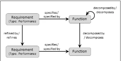
Figure 11 Performance Requirements Table 11 Performance Requirements
Element Class Attributes Relationships Target Classes
Function See Section 3.3 specified by / specifies Requirement
Requirement See Sections 1.2 and 2.1 refined by / refines Requirement
refines / refined by Requirement
3.5
Capture Functional and Performance Concerns and Risks
While developing the system’s functional hierarchy and deriving the associated performance requirements, additional concerns and risks may be identified. They should be captured in the repository in a manner analogous to Concerns and Risks resulting from the analysis of originating requirements (See Section 2.2).
Figure 12 Functional or Performance Requirement Concern and Risk Table 12 Functional or Performance Requirement Concern and Risk
Element Class Attributes Relationships Target Classes
Document See Section 2.2 documents /
documented by
Concern Risk
ExternalFile See Section 1.2 augments / augmented
by
Concern Risk
Function See Section 3.2 decomposed by /
decomposes
Function
decomposes / decomposed by
Table 12 Functional or Performance Requirement Concern and Risk
Element Class Attributes Relationships Target Classes
causes / caused by Risk
generates / generated by
Concern
result of / results in Concern Risk
Concern See Section 2.2 assigned to /
responsible for Organization documented by / documents Document generated by / generates Function Requirement
impacts / impacted by Component Function Interface Item Link Organization Product ProgramActivity ProgramElement Requirement Resource StateMode TestActivity TestConfiguration TestItem TestProcedure UseCase VerificationEvent VerificationRequirement
results in / result of Function Requirement
Table 12 Functional or Performance Requirement Concern and Risk
Element Class Attributes Relationships Target Classes
Organization See Section 2.2 responsible for /
assigned to
Concern Risk
ProgramActivity See Section 2.2 resolves / resolved by Risk
ProgramElement See Section 2.2 resolves / resolved by Risk
Requirement See Sections 1.2 and
2.1
causes / caused by Risk
generates / generated by
Concern
refined by / refines Requirement
refines / refined by Requirement
result of / results in Concern Risk
Risk See Section 2.2 assigned to /
responsible for
Organization
augmented by / augments
ExternalFile
caused by / causes Function Requirement
Table 12 Functional or Performance Requirement Concern and Risk
Element Class Attributes Relationships Target Classes
impacts / impacted by Component Function Interface Item Link Organization Product ProgramActivity ProgramElement Requirement Resource StateMode TestActivity TestConfiguration TestItem TestProcedure UseCase VerificationEvent VerificationRequirement
resolved by / resolves ProgramActivity ProgramElement
results in / result of Function Requirement
4
PHYSICAL ARCHITECTURE SYNTHESIS
4.1
Allocate Functions to Next Level of Components
In conjunction with the analysis of requirements, functional decomposition, and assessment of component technology, identify the next layer of Components in the system component hierarchy.
As the component hierarchy evolves, Functions are uniquely allocated toComponents. This allocation is done in layers. When a decomposed Function is allocated to a
Component, all lower-level Functions in its decomposition are part of the behavior of the Component. The Component may be further decomposed, in which case even lower-level Functions are allocated to the lower-level Components. At the leaf-level these allocations are termed Atomic. Since Functions can be aggregated to enhance understanding, there is not a one-to-one correspondence between levels in the
Function hierarchy and levels in the Component hierarchy.
Note: As stated in Section 3.2, when doing behavior development, a root Function can be established for any Component and the behavior diagram built using the allocated atomic Functions. This defines the full behavior of the Component from the
Component’s perspective rather than from the system perspective. These lower-level root Functions for lower-level Components do not appear in the system functional hierarchy, but act as access points into the hierarchy.
Table 13 Component Hierarchy and Function Allocation
Element Class Attributes Relationships Target Classes
Component Abbreviation Description Doc. PUID Purpose Number Type
built from / built in Component
built in / built from Component
performs / allocated to
Function
Function See Section 3.2 allocated to / performs Component
4.2
Refine External Interface Definitions
An external Interface element identifies the fact that the system communicates in some manner with an external Component (See Section 1.3). Details of the interface are captured in Link element definitions. As the system component hierarchy evolves, the terminus point for Interfaces and Links are changed, as appropriate, to lower-level
Components. The components that provide the Items for the Links are determined by the functional allocation. When the target of a joins or connects to relationship is changed from the system to one of its subordinates, CORE automatically establishes the
joined thru or connected thru relationship between the Interface or Link and ancestors of the subordinate Component including the system. This allows Interfaces and Links to retain their identity even though their end points may change as the component hierarchy grows in depth. This also allows the content of interface and formal higher-level component specifications to remain unchanged as the Interface/Link connection points move deeper into the system component hierarchy.
Interfaces and Links may be specified by performance and constraint Requirements. Only the lowest layer of Items should be transferred by a Link.
Table 14 External Interface Definition
Element Class Attributes Relationships Target Classes
Component See Section 4.1 connected thru /
connects thru11
Link
connected to / connects to
Link
joined to / joins Interface
joined thru / joins thru12
Interface
Interface See Section 1.3 comprised of / comprises Link
joins / joined to Component
joins thru / joined thru13
Component
specified by / specifies Requirement
Item See Section 3.2 transferred by / transfers Link
Link Capacity Capacity Units Delay Delay Units Description Doc. PUID Number Protocol comprises / comprised of Interface connects thru / connected thru14 Component connects to / connected to Component
specified by / specifies Requirement
transfers / transferred by
Item
Requirement See Section 2.1
Type: Performance or Constraint
specifies / specified by Interface Link
11
Automatically set based on the component hierarchy and connected to targets.
12
Automatically set based on the component hierarchy and joined to targets.
13
4.3
Derive or Refine Internal Interfaces
Within the system hierarchy, the allocation of Functions to Components establishes the internal interfaces of the system based on the Items that flow between the allocated
Functions. The internal interfaces are formalized in the repository using the Interface
and Link element classes.
As the system component hierarchy evolves further, the terminus point for Interfaces
and Links are changed, as appropriate, to lower-level Components. The components that provide the Items for the Links are determined by the functional allocation. When the target of joins or connects to is changed from a Component to one of its subordinates, CORE automatically establishes the joined thru or connected thru
relationship between the Interface or Link and the parent of the subordinate
Component. This allows Interfaces and Links to retain their identity even though the end points may change as the system component hierarchy grows in depth. This also allows the content of formal higher-level specifications to remain unchanged as the
Interface/Link connection points move deeper into the system component hierarchy.
Interfaces and Links may be specified by performance and constraint Requirements. Only the lowest layer of Items should be transferred by a Link.
Table 15 Internal Interface Definition
Element Class Attributes Relationships Target Classes
Component See Section 4.1 connected thru /
connects thru
Link15
connected to / connects to
Link
joined to / joins Interface
joined thru / joins thru Interface16
Interface See Section 1.3 comprised of /
comprises
Link
joins / joined to Component
joins thru / joined thru Component17
specified by / specifies Requirement
Item See Section 3.2 transferred by /
transfers
Link
Link See Section 4.2 comprises /
comprised of Interface connects thru / connected thru Component18 connects to / connected to Component
Requirement See Section 2.1
Type: Performance or Constraint
specifies / specified by Interface Link
15
Automatically set based on the component hierarchy and connected to targets.
16
Automatically set based on the component hierarchy and joined to targets.
17
4.4
Assign/Derive Constraints for Components
Based on the constraint Requirements allocated to a parent Component, constraint
Requirements are derived for the subcomponents. This can be a simple flow-down of the same requirement or may be a budgeting of a limitation, such as weight, between subcomponents.
Figure 16 Component Constraint Requirements Table 16 Component Constraint Requirements
Element Class Attributes Relationships Target Classes
Category Description categorizes /
categorized by
Requirement
(Type: Constraint)
Component
(Type: System)
See Section 1.1 specified by / specifies Requirement
(Type: Constraint) Requirement (Type: Constraint) See Section 1.2 Type: Constraint categorized by / categorizes Category
refined by / refines Requirement
(Type: Constraint)
refines / refined by Requirement
(Type: Constraint)
specifies / specified by Component
4.5
Capture Physical Architecture Concerns and Risks
While developing the physical architecture and deriving Interfaces and performance/constraint Requirements, additional concerns and risks may be identified. These should be captured in the repository in a manner analogous to Concerns and
Risks resulting from the analysis of originating Requirements (See Section 2.2).
Table 17 Physical Architecture Concern and Risk
Element Class Attributes Relationships Target Classes
Component See Section 4.1 causes / caused by Concern
generates / generated by
Risk
Document See Section 2.2 documents /
documented by
Concern Risk
ExternalFile See Section 1.2 augments / augmented
by
Concern Risk
Function See Section 3.2 result of / results in Concern
Risk
Interface See Section 1.3 causes / caused by Risk
generates / generated by
Concern
Concern See Section 2.2 assigned to /
responsible for Organization documented by / documents Document generated by / generates Component Interface Link Requirement
results in / result of Function Requirement
Link See Section 4.2 causes / caused by Risk
generates / generated by
Concern
Organization See Section 2.2 responsible for /
assigned to
Concern Risk
ProgramActivity See Section 2.2 resolves / resolved by Risk
ProgramElement See Section 2.2 resolves / resolved by Risk
Requirement See Sections 1.2 and 2.1 causes / caused by Risk
generates / generated by
Table 17 Physical Architecture Concern and Risk
Element Class Attributes Relationships Target Classes
refined by / refines Requirement
refines / refined by Requirement
result of / results in Concern Risk
Risk See Section 2.2 assigned to /
responsible for
Organization
augmented by / augments
ExternalFile
caused by / causes Component Interface Link
Requirement
resolved by / resolves ProgramActivity ProgramElement
results in / result of Function Requirement
5
VERIFICATION/VALIDATION
5.1
COREsim
COREsim is a discrete event simulator that executes the functional and link viewpoints to provide an assessment of system performance and to verify the dynamic integrity of the conceptual view. COREsim dynamically interprets a behavior viewpoint (i.e., the Enhanced Functional Flow Block Diagram (EFFBD)) in conjunction with the component link view and identifies and displays timing, resource utilization, link flow, and viewpoint inconsistencies. COREsim usage should be an integral part of functional analysis and physical architecture synthesis.
5.2
Establish Verification Requirements
For each specified Component, including the system, establish how each Requirement
is to be verified. This information is captured in the repository using
VerificationRequirements. VerificationRequirements can range from requirements on acceptance testing such as qualification test to verification of individual Requirements
and Functions. A single VerificationRequirement may verify multiple requirements.
Table 18 Verification Requirements
Element Class Attributes Relationships Target Classes
Function See Section 3.2 verified by / verifies Verification
Requirement
Requirement See Section 2.1 verified by / verifies Verification
Requirement Verification Requirement Description Doc. PUID Level Method Number
verifies / verified by Function Requirement
5.3
Establish Verification Events and Test Procedures
Actual verification activities are captured in the repository as VerificationEvents.
TestProcedures identify the procedures. It is assumed that the actual test steps and expected results are external to the CORE repository and are referenced in the repository using either Document or ExternalFile elements. TestConfigurations identify the equipment and facilities needed for particular VerificationEvents. A
TestConfiguration identifies Components of the system and Links to the Components
as well as test equipment and software. As verification events are planned and conducted, the VerificationRequirement's Status attribute is updated in the repository.
Table 19 Verification Planning and Tracking
Element Class Attributes Relationships Target Classes
Component See Section 4.1 forms / formed by TestConfiguration
Document Description
External File Path Number
documents / documented by
TestProcedure
ExternalFile See Section 1.2 augments / augmented
by
TestProcedure
Link See Section 4.1 forms / formed by TestConfiguration
Organization See Section 2.2 responsible for /
assigned to
VerificationEvent TestConfiguration Description
Number
formed by / forms Component Link
employed by / employs VerificationEvent
TestProcedure Description
Number
employed by / employs VerificationEvent
augmented by / augments ExternalFile VerificationEvent Description Duration Duration Units End Date Number Start Date assigned to / responsible for Organization employs / employed by TestConfiguration TestProcedure
fulfills / fulfilled by VerificationRequirement
included in / includes VerificationEvent
includes / included in VerificationEvent Verification
Requirement
See Section 5.2 fulfilled by / fulfills VerificationEvent
5.4
Test Planning
Test program support and planning are captured in the CORE repository using the
TestActivity and TestItem classes. These classes are analogous to the Function and Item
classes. From a behavioral perspective there is no difference among these classes. There are some attribute and relational differences, however. Overall and individual test planning in CORE begins with defining major test threads for the system and culminates in an integrated behavior view of the system, subsystem, etc., test actions. For the
program or project, a top-level TestActivity should be defined and associated with a
ProgramElement using the accomplishes / accomplished by relationship pair. The
accomplishes relationship attribute behaviorType should be set to “Integrated (Root)” in order to identify that this top-level TestActivity represents the totality of testing needed to satisfy the test objectives of the program/system represented by the associated
ProgramElement. The root TestActivity may be decomposed (hierarchically) into all of the activities needed to satisfactorily define the test plan for the program/system. A
TestItem is an input to, an output from or triggers a TestActivity. TestItems are the control indicators or measurables associated with a TestActivity, i.e., test data. A
TestActivity is established by a Requirement, executes a VerificationRequirement and possibly resolves a Risk.
Table 20 Test Planning
Element Class Attributes Relationships Target Classes
ExternalFile See Section 1.2 augments /
augmented by
TestActivity TestItem
ProgramElement See Section 2.2 accomplished by /
accomplishes
TestActivity
assigned to / responsible for
Organization
includes / included in ProgramElement
included in / includes ProgramElement
resolves / resolved by Risk
specified by / specifies Requirement
supplies / supplied by Component Document TestActivity Description End Date Prerequisite Special Comments Start Date Test Completion Criteria Type decomposes / decomposed by TestActivity decomposed by / decomposes TestActivity accomplishes / accomplished by ProgramElement established by / establishes Requirement executes / executed by VerificationRequirement
inputs / input to TestItem
outputs / output from TestItem
resolves / resolved by Risk triggers / triggered by TestItem TestItem Description Size Size Units augmented by / augments ExternalFile decomposed by /decomposes TestItem
Table 20 Test Planning
Element Class Attributes Relationships Target Classes
Type decomposes /
decomposed by
TestItem
input to / inputs TestActivity
output from / outputs TestActivity
triggers / triggered by
TestActivity
Requirement See Sections 1.2 and
2.1
establishes / established by
TestActivity
Risk See Section 2.2 resolves /
resolved by
ProgramActivity ProgramElement TestActivity VerificationRequirement See Section 5.2 executed by / executes TestActivity
6
CHANGE MANAGEMENT SUPPORT
The CORE repository provides Change Management Support through the use of the
ChangeRequestPackage class. The ChangeRequestPackage class allows the capture of system design changes and their impacts upon the model held in the CORE repository. A
ChangeRequestPackage class element contains the basic characteristics of the change proposal presented to the system’s change approval agent and may be augmented by one or more ExternalFile elements. The need for a formal change request occurs when there appears a need to change the source requirements or change the affected system’s baseline. These changes to the system may arise from internal and external organizations and the source of the change proposal the originates by / originates
relationship pair associates the Organization element with the proposed
ChangeRequestPackage element. Also the ChangeRequestPackage element is assigned to one or more organizational elements for review. The ChangeRequestPackage
element may be generated by one or more of the Component, Function, Interface, Link,
Organization, Requirement, Resource, UseCase, or VerificationRequirement classes. As an outcome of the analysis and review by the various Organizations the impacts upon the system design will be established and the benefits and deficiencies of the proposed change are uncovered and presented to the system’s change approval agent.