for Cisco Unified ICM/Contact Center Enterprise & Hosted
ICM Software Releases 7.x(y)October 2009
Americas Headquarters
Cisco Systems, Inc. 170 West Tasman Drive San Jose, CA 95134-1706 USA http://www.cisco.com Tel: 408 526-4000 800 553-NETS (6387) Fax: 408 527-0833
THE SPECIFICATIONS AND INFORMATION REGARDING THE PRODUCTS IN THIS MANUAL ARE SUBJECT TO CHANGE WITHOUT NOTICE. ALL STATEMENTS, INFORMATION, AND RECOMMENDATIONS IN THIS MANUAL ARE BELIEVED TO BE ACCURATE BUT ARE PRESENTED WITHOUT WARRANTY OF ANY KIND, EXPRESS OR IMPLIED. USERS MUST TAKE FULL RESPONSIBILITY FOR THEIR APPLICATION OF ANY PRODUCTS.
THE SOFTWARE LICENSE AND LIMITED WARRANTY FOR THE ACCOMPANYING PRODUCT ARE SET FORTH IN THE INFORMATION PACKET THAT SHIPPED WITH THE PRODUCT AND ARE INCORPORATED HEREIN BY THIS REFERENCE. IF YOU ARE UNABLE TO LOCATE THE SOFTWARE LICENSE OR LIMITED WARRANTY, CONTACT YOUR CISCO REPRESENTATIVE FOR A COPY.
The Cisco implementation of TCP header compression is an adaptation of a program developed by the University of California, Berkeley (UCB) as part of UCBs public domain version of the UNIX operating system. All rights reserved. Copyright 1981, Regents of the University of California. NOTWITHSTANDING ANY OTHER WARRANTY HEREIN, ALL DOCUMENT FILES AND SOFTWARE OF THESE SUPPLIERS ARE PROVIDED "AS IS" WITH ALL FAULTS. CISCO AND THE ABOVE-NAMED SUPPLIERS DISCLAIM ALL WARRANTIES, EXPRESSED OR IMPLIED, INCLUDING, WITHOUT LIMITATION, THOSE OF MERCHANTABILITY, FITNESS FOR A PARTICULAR PURPOSE AND NONINFRINGEMENT OR ARISING FROM A COURSE OF DEALING, USAGE, OR TRADE PRACTICE.
IN NO EVENT SHALL CISCO OR ITS SUPPLIERS BE LIABLE FOR ANY INDIRECT, SPECIAL, CONSEQUENTIAL, OR INCIDENTAL DAMAGES, INCLUDING, WITHOUT LIMITATION, LOST PROFITS OR LOSS OR DAMAGE TO DATA ARISING OUT OF THE USE OR INABILITY TO USE THIS MANUAL, EVEN IF CISCO OR ITS SUPPLIERS HAVE BEEN ADVISED OF THE POSSIBILITY OF SUCH DAMAGES.
CCDE, CCENT, CCSI, Cisco Eos, Cisco HealthPresence, Cisco IronPort, the Cisco logo, Cisco Lumin, Cisco Nexus, Cisco Nurse Connect, Cisco Pulse, Cisco StackPower, Cisco StadiumVision, Cisco TelePresence, Cisco Unified Computing System, Cisco WebEx, DCE, Flip Channels, Flip for Good, Flip Mino, Flipshare (Design), Flip Ultra, Flip Video, Flip Video (Design), Instant Broadband, and Welcome to the Human Network are trademarks; Changing the Way We Work, Live, Play, and Learn, Cisco Capital, Cisco Capital (Design), Cisco:Financed (Stylized), Cisco Store, and Flip Gift Card are service marks; and Access Registrar, Aironet, AllTouch, AsyncOS, Bringing the Meeting To You, Catalyst, CCDA, CCDP, CCIE, CCIP, CCNA, CCNP, CCSP, CCVP, Cisco, the Cisco Certified Internetwork Expert logo, Cisco IOS, Cisco Press, Cisco Systems, Cisco Systems Capital, the Cisco Systems logo, Cisco Unity, Collaboration Without Limitation, Continuum, EtherFast, EtherSwitch, Event Center, Explorer, Fast Step, Follow Me Browsing, FormShare, GainMaker, GigaDrive, HomeLink, iLYNX, Internet Quotient, IOS, iPhone, iQuick Study, IronPort, the IronPort logo, Laser Link, LightStream, Linksys, MediaTone, MeetingPlace, MeetingPlace Chime Sound, MGX, Networkers, Networking Academy, Network Registrar, PCNow, PIX, PowerKEY, PowerPanels, PowerTV, PowerTV (Design), PowerVu, Prisma, ProConnect, ROSA, ScriptShare, SenderBase, SMARTnet, Spectrum Expert, StackWise, The Fastest Way to Increase Your Internet Quotient, TransPath, WebEx, and the WebEx logo are registered trademarks of Cisco Systems, Inc. and/or its affiliates in the United States and certain other countries.
All other trademarks mentioned in this document or website are the property of their respective owners. The use of the word partner does not imply a partnership relationship between Cisco and any other company. (0908R)
Any Internet Protocol (IP) addresses used in this document are not intended to be actual addresses. Any examples, command display output, and figures included in the document are shown for illustrative purposes only. Any use of actual IP addresses in illustrative content is unintentional and coincidental.
Preface ...1 Purpose ...1 Audience ...2 Organization ...2 Related Documentation ...3 Conventions...4
Obtaining Documentation and Submitting a Service Request...4
Documentation Feedback...5
1. Encryption Support...7
User and Agent Passwords...7
Call Variables and Extended Call Variables...7
Internet Script Editor, Agent Reskilling and WebView...8
CTI OS C++/COM Toolkit...8
Cisco Contact Center SNMP Management Service...9
Cisco Support Tools...9
Additional Encryption...9
2. IPSec and NAT Support...11
About IPSec...11
About NAT...12
Support for IPSec (IP Security) in Tunnel Mode...12
Support for IPSec (IP Security) in Transport Mode...13
System Requirements...13
Supported Communication Paths ...13
Configuring IPSec Policy...15
IPSec Connection to Cisco CallManager...17
Monitoring IPSec Activity...17
IPSec Monitor...17
IPSec Logging...17
Network Monitoring...18
System Monitoring ...18
Securing Support Tools Using IPSEC...19
Support Tools IPSEC Configuration Example...? Support for NAT (Network Address Translation)...20
NAT and CTI OS...20
IPSec and NAT Transparency...21
Additional IPSec References...21
3. Applying IPSec with the Network Isolation Utility...23
About IPSec...23
Deploying IPSec Manually Versus Deploying It Via the Network Isolation Utility...24
About the Cisco Network Isolation Utility...24
An Illustration of Network Isolation Utility Deployment...25
How the Network Isolation Utility Works...25
IPSec Terminology...25
The Network Isolation Utility Process...26
About Encrypting Traffic...27
Sample Deployment...28
Devices That Must Communicate with One Another...33
Typical Boundary Devices...34
Caveats...36
How to Do a Batch Deployment...37
How to Run the Network Isolation Utility from the Command Line...37
How to Monitor the Network Security...42
Troubleshooting the Network Isolation IPSec Policy...42
4. Windows Server 2003 Firewall Configuration...43
Cisco Firewall Configuration Utility Prerequisites...44
Using the Cisco Firewall Configuration Utility...45
Verifying New Windows Firewall Settings...45
Configuring Windows Server 2003 Firewall to Communicate With Active Directory...46
Configuring Domain Controller Ports...46
Restrict FRS Traffic to a Specific Static Port...46
Restrict Active Directory replication traffic to a specific port...47
Configure Remote Procedure Call (RPC) port allocation...47
Windows Server 2000 and 2003 Firewall Ports...47
Testing Connectivity...48
Validating Connectivity...48
Understanding the CiscoICMfwConfig_exc.xml File...49
Troubleshooting Windows Firewall...50
General Troubleshooting Notes...50
Windows Firewall Interferes with Router Private Interface Communication...50
Windows Firewall Shows Dropped Packets but no ICM or IPCC Failures are Evident...50
Undo Firewall Settings...51
5. Automated Security Hardening Settings on Windows Server 2003...53
Applying/Removing Cisco ICM Security Settings...54
Applying Cisco ICM Security Settings During Setup...54
Manually Installing Cisco ICM Security Settings...55
Rolling Back Security Settings...55
Account Policies Settings...56
Password Policy...56
Account Lockout Policy...57
Kerberos Policy...57
Local Policies...57
Audit Policy...57
User Rights Assignment...58
Security Options...61
Event Log...70
System Services...70
Settings for System Services...71
Registry...77
File System...78
6. Applying Security with the Cisco Unified Contact Center Security Wizard...81
About the Cisco Unified Contact Center Security Wizard...81
Configuration and Restrictions...82
How to Install the Wizard...82
Example Network Isolation Configuration Panels...92
7. Updating Microsoft Windows ...97
Microsoft Security Updates...97
Microsoft Service Pack Policy...98
Configuring the Server to use an Alternate Windows Update Server...99
8. SQL Server Hardening...101
SQL Server Hardening Suggestions...101
Top Hardening Suggestions...101
SQL Server Users and Authentication...104
SQL Server 2005 Security Considerations...105
Automated SQL 2005 Hardening...105
SQL Server Security Hardening Utility...106
Manual SQL 2005 Server Hardening...107
9. Cisco SSL Encryption Utility...109
About the SSL Encryption Utility...109
Installing SSL During Setup...110
SSL Encryption Utility in Standalone Mode...110
Enabling the Transport Layer Security (TLS) 1.0 Protocol...112
10. Intrusion Prevention and Cisco Security Agent...113
What are Cisco Security Agent Policies?...113
Types of Agents...114
Managed Agent...114
Standalone Agent...114
11. Microsoft Baseline Security Analyzer (MBSA)...115
Security Update Scan Results...116
Windows Scan Results...116
Internet Information Services (IIS) Scan Results...117
SQL Server Scan Results...118
Desktop Application Scan Results...119
12. Auditing ...121
How to View Auditing Policies...121
Security Log...122
Real-Time Alerts...122
SQL Server Auditing Policies...122
SQL Server C2 Security Auditing...122
Active Directory Auditing Policies...123
13. General Anti-Virus Guidelines and Recommendations...125
Guidelines and Recommendations...126
ICM/IPCC Software Maintenance Parameters...127
Logger Recommendations ...127
Distributor Recommendations...127
Router and PG Recommendations...128
Other Scheduled Tasks Recommendations...128
File Type Exclusion Recommendations...128
Windows Terminal Services (Remote Desktop)...129
Remote Desktop...130
Securing the RDP-TCP Connection...130
Per-User Terminal Services Settings...131
pcAnywhere...131
Restricting access to internal machines...132
Preventing unauthorized connections to a pcAnywhere host...132
Protecting the data stream during a remote control session...134
Preventing unauthorized changes to the installed product...134
Identifying security risks...134
Logging events during a remote control session...135
VNC...135
TRIDIA VNC Pro...135
15. Additional Security Best Practices...137
Additional Cisco Call Center Applications...137
Cisco ICM WebView...137
Cisco ICM CTI Object Server (CTI OS)...138
Cisco Agent Desktop (CAD)...138
Cisco ICM Router...138
Peripheral Gateways (PGs) and IPCC Enterprise Agent Login...139
CTI OS and Monitor Mode Connection...139
Microsoft Internet Information Server (IIS)...139
Hardening IIS for use with WebView and Internet Script Editor on Windows 2000 Platforms...139
Sybase EAServer (Jaguar) Hardening...142
Starting Jaguar Manager...142
Changing Jaguar Password...143
Restart WebView/Services...144
RMS Listener Hardening...144
WMI Service Hardening...145
WMI namespace-level security:...145
Additional WMI Security Considerations...146
SNMP Hardening...146
Toll Fraud Prevention...147
Syskey...148
Third-Party Security Providers...148
Figure 1: Example Network Isolation Deployment...25
Figure 2: Example Contact Center Enterprise System...29
Figure 3: Example Phase 1 - Step 1 IPSec Deployment...29
Figure 4: Example Tusted Device Isolation...30
Figure 5: Example Phase 1 - Step 2 IPSec Deployment...30
Figure 6: Example Phase 1 - Step 3 IPSec Deployment...31
Figure 7: Example Phase 2 - Step 1 IPSec Deployment...31
Figure 8: Example Phase 2 - Step 2 IPSec Deployment...32
Figure 9: Example IPSec Deployment - Overall Design...32
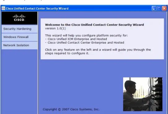
Figure 10: Example Security Wizard Welcome Panel...85
Figure 11: Example Security Hardening Introduction Panel...86
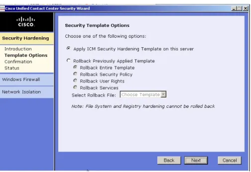
Figure 12: Example Security Hardening Template Options Panel...86
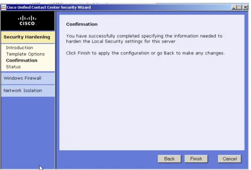
Figure 13: Example Security Hardening Confirmation Panel...87
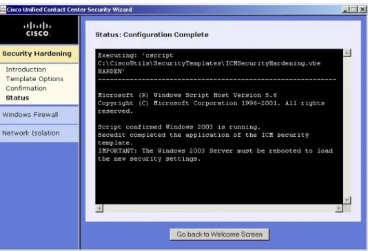
Figure 14: Example Security Hardening Status Panel...88
Figure 15: Example Windows FireWall Wizard Introduction Panel...88
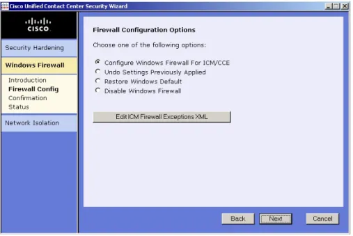
Figure 16: Example Firewall Configuration Options Panel...89
Figure 17: Example Firewall Confirmation Panel...90
Figure 18: Example Firewall Status Panel...91
Figure 19: Example Network Isolation Introductory Panel...92
Figure 20: Example Trusted Devices Configuration Panel...93
Figure 21: Example Boundary Device Panel...94
Figure 22: Example Network Isolation Confirmation Panel...95
Figure 23: Example Network Isolation Status Panel...95
Figure 24: SSL Config Utility - Configuration Tab...111
Purpose
This document describes security hardening configuration guidelines for Cisco ICM Software Release 7.x(y) on Windows Server 2003. The term "ICM software" includes: IP Contact Center (IPCC) Enterprise and Hosted Editions, System IPCC, and ICM Enterprise and Hosted Editions. Optional ICM applications applying to these server configurations are also addressed here, with the exception of the following: Web Collaboration Option Collaboration Server, Media Blender (when not co-resident with a PG; if co-resident with a PG then these best practices are applicable), Dynamic Content Adapter and E-mail Manager Option. References throughout this document to "ICM/IPCC" will assume the aforementioned configurations. Any accompanying applications making up the customer's particular solution, whether Cisco provided - such as PSO applications - or provided by a Cisco partner, have not been approved for use with these security hardening recommendations. Special testing and qualification must be considered to ensure that
recommended security configurations do not hinder the operation of those applications. The configurations presented in this document represent parameters used internally within Cisco to develop and test the applications. Other than the base Operating System and applications' installations, any deviation from this set cannot be guaranteed to provide a compatible operating environment. It is important to note recommendations contained in this document will not always be uniformly implemented; some implementations - as based on corporate policy, specific IT utilities (e.g., backup accounts) or other external guidelines - may modify or limit the application of these guidelines.
Note: Security Hardening for Release 7.x(y) is supported on Windows 2003 only when the
server has been hardened using the 6.0 guidelines. You cannot upgrade a non-hardened Windows 2000 server from ICM 5.0 or 6.0 to ICM 7.x(y) and then apply hardening. First harden the Windows 2000 Server running a previous version of ICM before upgrading to 7.x(y). The other option is to upgrade the Operating System to Windows Server 2003 after upgrading the ICM/IPCC software and then applying the automated hardening described in this guide.
Audience
This document is primarily intended for server administrators and OS and application installers. It is assumed that the target reader of this document is an experienced administrator familiar with Windows 2003 and Windows Server 2003 installations. It is further assumed that the reader is fully familiar with the applications making up the ICM/IPCC solution, as well as with the installation and administration of these systems. It is the intent of these best practices to additionally provide a consolidated view of securing the various third-party applications on which the Cisco contact center applications depend. Should vendor recommendations differ from these guidelines, following such recommendations may result in systems that are not protected from malicious attacks.
Organization
This document is organized into the following chapters: Description
Chapter
A brief overview of the encryption methods used in ICM/IPCC Encryption Support
Security Best Practices of deploying IPSec and NAT in an ICM/IPCC Environment.
IPSec and NAT Support
The use of Windows Firewall and details about Cisco's Windows Firewall configuration script.
Windows Server 2003 Firewall Configuration
Specific details of the settings changed when using the Cisco Security Template.
Automated Security Hardening Settings on Windows Server 2003
Security Best Practices to use when updating Windows Server 2003. Updating Microsoft Windows
Security Best Practices for SQL Server SQL Server Hardening
Details on using the SSL Encryption Utility Cisco SSL Encryption Utility
Using Cisco Security Agent for Host Intrusion Detection. Intrusion Prevention and Cisco Security Agent
Example of what to expect when running MBSA on a typical ICM Server. Microsoft Baseline Security Analyzer (MBSA)
Security Best Practices for setting Auditing Policies on ICM/IPCC Servers.
Auditing
General Anti-Virus Guidelines and Recommendations General Anti-Virus Guidelines and
Recommendations
Preface Audience
Description Chapter
Security Best Practices to consider when using various remote administration applications.
Remote Administration
Additional Security Best Practices on: Additional Security Best Practices
• Additional Cisco Call Center Applications • Microsoft Internet Information Server • Sybase EAServer (Jaguar)
• RMS Listener Hardening • WMI Service Hardening • SNMP Service Hardening • Toll Fraud Prevention • Syskey
• Third-party Security Providers • Third Part Management Agents
Related Documentation
The recommendations contained herein are based in part on hardening guidelines published by Microsoft, such as those found in the Windows Server 2003 Security Hardening Guide, as well as other third-party vendors' hardening recommendations. A number of recommendations are made fully consistent with supporting Microsoft guidelines; our intent is to further interpret and customize those guidelines as specifically applicable to the ICM/IPCC server products. This document should be used in conjunction with the Planning and Staging Guides that are part of the ICM/IPCC documentation. It should further be used as a reference standard for all customers requiring verification that certain security configuration changes to the base operating system and contact center application servers have been certified for use with the ICM/IPCC applications. The average time to execute the majority of the steps has been reduced significantly due to the automation and integration with the impacted products installation programs. More information can be found in the following documents:
• Staging Guide: Cisco ICM/IPCC Enterprise & Hosted Editions
• Microsoft Windows Server 2003 Security Hardening Guide (http://www.microsoft.com/ technet/security/prodtech/windowsserver2003/W2003HG/SGCH00.mspx)
Conventions
This manual uses the following conventions: Description Convention
Boldface font is used to indicate commands, such as user entries, keys, buttons, and folder and submenu names. For example:
boldface font
• Choose Edit > Find. • Click Finish.
Italic font is used to indicate the following: italic font
• To introduce a new term. Example: A skill group is a collection of agents who share similar skills.
• For emphasis. Example: Do not use the numerical naming convention.
• A syntax value that the user must replace. Example: IF (condition, true-value, false-value)
• A book title. Example: See the Cisco CRS Installation Guide. Window font, such as Courier, is used for the following: window font
• Text as it appears in code or that the window displays. Example: <html><title>Cisco Systems,Inc. </ title></html>
Angle brackets are used to indicate the following: < >
• For arguments where the context does not allow italic, such as ASCII output.
• A character string that the user enters but that does not appear on the window such as a password.
Obtaining Documentation and Submitting a Service Request
For information on obtaining documentation, submitting a service request, and gathering additional information, see the monthly What's New in Cisco Product Documentation, which also lists all new and revised Cisco technical documentation, at:
Preface Conventions
http://www.cisco.com/en/US/docs/general/whatsnew/whatsnew.html
Subscribe to the What's New in Cisco Product Documentation as a Really Simple Syndication (RSS) feed and set content to be delivered directly to your desktop using a reader application. The RSS feeds are a free service and Cisco currently supports RSS version 2.0.
Documentation Feedback
You can provide comments about this document by sending email to the following address: mailto:[email protected]
Preface Documentation Feedback
Encryption Support
This section describes the types of encryption used in the ICM system. The concepts should aid you in understanding how encryption is used in the ICM/IPCC environment.
This chapter contains the following topics: • User and Agent Passwords, page 7
• Call Variables and Extended Call Variables, page 7
• Internet Script Editor, Agent Reskilling and WebView, page 8 • CTI OS C++/COM Toolkit, page 8
• Cisco Contact Center SNMP Management Service, page 9 • Cisco Support Tools, page 9
• Additional Encryption, page 9
User and Agent Passwords
Cisco ICM/IPCC systems are highly distributed applications composed of many node and server applications. Applications users' and contact center agents' passwords are stored in the Cisco ICM Logger databases as well as the Distributor databases as an RSA Data Security, Inc. MD5 Message-Digest Algorithm hash. When passed from one server node to another, such as from a Peripheral Gateway to a Router, or from a Distributor to a Router or a Logger, they are passed as MD5 hashes as opposed to clear text.
Call Variables and Extended Call Variables
To protect data sent in call variables or ECC variables, Cisco ICM relies on IPSec and the deployment of IPSec policies between servers running Windows Server 2003. In an IPCC environment, the establishment of an IPSec channel between the Cisco Call Manager and the Peripheral Gateway is also supported. The recommended integrity algorithm is SHA-1 and the
encryption algorithm is 3DES. The recommended IKE security algorithm is a minimum of Diffie-Hellman Group 2 for a 1024-bit key or 2048-bit key if processing power allows it.
See Also
IPSec and NAT Support on page 11
Internet Script Editor, Agent Reskilling and WebView
Release 7.x(y) of Cisco ICM supports, as a default on Windows 2003 Server, the encryption of traffic for users accessing the ICM Internet Script Editor, Agent Reskilling, and WebView applications so that all user logins and optionally session traffic done from a remote machine are protected from snooping. The applications are HTTP based that implement the SSL v3.0 protocol using the OpenSSL libraries.
The Agent Reskilling and Internet Script Editor web applications will also be deployed and enabled for 128-bit SSL encryption in IIS 6.0 as a default so that all supervisor logins, user logins, and data exchanged is protected across the network.
For WebView, the authentication phase is encrypted with 128-bit encryption by default. As an option, users may decide to encrypt the entire session which may be done during installation or afterwards using the SSL Encryption Utility.
For more information on enabling certain Cipher Suites in IIS see: http://support.microsoft.com/ ?kbid=245030
See Also
Cisco SSL Encryption Utility on page 109
Cisco WebView Documentation
CTI OS C++/COM Toolkit
The CTI OS (C++/COM toolkit) and CAD agent desktops implement TLS v1.0 protocol using the OpenSSL libraries to protect data exchanged from the agent desktop to the CTI Object Server. A Cipher suite is used for authentication, key exchange, and stream encryption. The Cipher suite is as follows:
• Key exchange: Diffie-Hellman • Authentication: RSA
• Encryption: AES (128)
• Message digest algorithm: SHA1
Refer to the CTI OS System Manager's Guide and Cisco CAD Installation Guide for more configuration details.
Chapter 1: Encryption Support Internet Script Editor, Agent Reskilling and WebView
Cisco Contact Center SNMP Management Service
The ICM/IPCC software includes an SNMP v3 agent to support authentication and encryption (privacy) provided by SNMP Research International. Cisco's implementation exposes the configuration of the communication with a management station to be authenticated using the MD5 or SHA-1 digest algorithms, and for all SNMP messages to be encrypted using one of the following three protocols: 3DES, AES-192, or AES-256.
See Also
SNMP Hardening on page 146
SNMP Guide for Cisco ICM/IPCC Enterprise & Hosted Editions
Cisco Support Tools
The Cisco Support Tools for Cisco IPCC is a serviceability application that is deployed with SSL enabled by default. This ensures all data exchanged from the browser to the server and vice versa as well as user logins are encrypted with 128-bit encryption.
Additional Encryption
In addition to the various areas of application level encryption provided in the Cisco ICM suite of applications, Cisco supports the deployment of the solution across sites running Cisco IOS(TM) IPSec in Tunnel Mode with HMAC-SHA1 Authentication (ESP-SHA-HMAC) and 3DES Encryption (ESP-3DES).
See Also
Chapter 1: Encryption Support Additional Encryption
IPSec and NAT Support
About IPSec
Internet Protocol security (IPSec) is a framework of open standards for ensuring private, secure communications over Internet Protocol (IP) networks, through the use of cryptographic security services.
Note: IPSec can be deployed in many different ways. The purpose of this chapter is to explain
what IPSec is and how to secure selected communication paths using IPSec. The chapter on Applying IPSec with the Network Isolation Utility (page 23) explains a specific, more restricted, but automated way of applying IPSec to secure the entire traffic to and from the server. The Network Isolation Utility can also save you a lot of work in applying IPSec. However, if you use that utility to apply IPSec, you should also read this chapter to understand the various IPSec deployment options and to use the one that is the most beneficial for your environment. For more information, see http://www.cisco.com/go/ipsec and http://www.microsoft.com/ resources/documentation/WindowsServ/2003/standard/proddocs/en-us/
sag_IPSECtopnode.asp
Implementing IPSec in an ICM or IPCC environment means finding a balance between ease of deployment and usability, and protecting sensitive information from unauthorized access. Finding the proper balance requires:
• Assessing the risk and determining the appropriate level of security for your organization. • Identifying valuable information.
• Defining security policies that use your risk management criteria and protect the identified information.
• Ensuring that management and technology requirements are in place.
Security considerations are also influenced by the way the application will be used or deployed. For example, the required security might differ, depending on whether certain ICM/IPCC servers will be deployed in a single data center or across a number of sites which may or may not communicate across trusted networks. The security framework in Windows Server 2003 is designed to fulfill the most stringent security requirements. However, software alone might be less effective without careful planning and assessment, effective security guidelines, enforcement, auditing, and sensible security policy design and assignment.
About NAT
Network Address Translation (NAT) is a mechanism for conserving registered IP addresses in large networks and simplifying IP addressing management tasks. As its name implies, NAT translates IP addresses within private "internal" networks to "legal" IP addresses for transport over public "external" networks (such as the Internet). Incoming traffic is translated back for delivery within the inside network.
The section in this chapter beginning with Support for NAT (Network Address Translation) (page 20) describes the ICM and IPCC NAT support.
Support for IPSec (IP Security) in Tunnel Mode
Due to increased security concerns in the deployment of data and voice networks alike, ICM and IPCC Enterprise deployments now add support for IPSec between Central Controller sites and remote Peripheral (PG) sites. This secure network implementation implies a distributed model where the WAN connection is secured via IPSec tunnels. The testing undertaken in this release was limited to configuration of Cisco IOS(TM) IPSec in Tunnel Mode, meaning only the Cisco IP Routers (IPSec peers) between the two sites were part of the secure channel establishment. All data traffic is encrypted across the WAN link but un-encrypted on the local area networks. In tunnel mode, traffic flow confidentiality is ensured between IPSec peers which, in this case, are the IOS Routers connecting a central site to a remote site.
The qualified specifications for the IPSec configuration are as follows: • HMAC-SHA1 Authentication (ESP-SHA-HMAC)
• 3DES Encryption (ESP-3DES)
We highly recommend that hardware encryption be used in order to avoid a significant increase in IP Router CPU overhead and throughput impact. There are also some latency implications, so it is important to size the network infrastructure (network hardware and physical links) accordingly. There are also considerations that must be taken for QoS networks. The common recommendation is to classify and apply QoS features based on packet header information before traffic is tunnel encapsulated and/or encrypted.
Chapter 2: IPSec and NAT Support About NAT
More detailed resources on Cisco IOS IPSec functionality can be found at http://www.cisco.com/ go/ipsec
Support for IPSec (IP Security) in Transport Mode
System Requirements
System Requirements for IPSec Support in Transport Mode • Cisco ICM Release 7.x
• Microsoft®) Windows®) Server 2003
• Intel PRO/100 S Server Adapter P/N PILA8470C3
Note:
• IPSec offload network adapters accelerate the cryptographic operations used to secure IPSec packets, therefore minimizing the performance costs for encryption. As a result, IPSec -secured TCP/IP connections can achieve similar throughput as TCP/IP connections that are not secured using IPSec. If the hardware acceleration cards cannot be used, then IPSec encryption will increase CPU load, and decrease throughput.
• ICM Release 7.x support for IPSec is contingent on the use of network interface cards which support IPSec offloads. The card listed in the System Requirements list is what has been tested and is recommended.
See Also
For more information about the benefits of using IPSec hardware offload adapters, see "Intel PRO/100S Network Adapter, IPSec Offload Performance and Comparison," at http:// www.veritest.com/clients/reports/intel/intelps.pdf.
Supported Communication Paths
ICM Release 7.x supports deploying IPSec in a Windows Server 2003 operating environment to secure server to server communication. The support is limited to the following list of nodes which exchange customer sensitive data.
1. NAM Router - CICM Router
2. ICM Router Side A - ICM Logger Side A (visible path) 3. ICM Router Side B - ICM Logger Side B (visible path) 4. ICM Router Side A - ICM Router Side B (private path)
6. ICM Router - ICM Peripheral Gateway (PG)
a. ICM Router Side A - ICM PG Side A
b. ICM Router Side A - ICM PG Side B
c. ICM Router Side B - ICM PG Side A
d. ICM Router Side B - ICM PG Side B
7. ICM Router - ICM Real-time Distributor (Primary/Secondary)
a. ICM Router Side A - ICM Real-time Distributor (Primary/Secondary)
b. ICM Router Side B - ICM Real-time Distributor (Primary/Secondary) 8. ICM Logger - ICM Real-time Distributor (Primary/Secondary) with HDS
a. ICM Logger Side A - ICM Real-time Distributor (Primary/Secondary) with HDS
b. ICM Logger Side B - ICM Real-time Distributor (Primary/Secondary) with HDS 9. ICM PG Side A - ICM PG Side B
a. visible path
b. private path
10. ICM PG Side A/B - Cisco CallManager (IPCC)
For the server communication paths identified, the following security level should be considered a general basis for planning an IPSec deployment:
• High security
Computers that contain highly sensitive data are at risk for data theft, accidental or malicious disruption of the system, or any public network communications. Secure Server (Require Security), a default policy, requires IPSec protection for all traffic being sent or received (except initial inbound communication) with stronger security methods. Unsecured communication with a non-IPSec-aware computer is not allowed.
See Also
Be sure to consult the Microsoft Knowledge Base article IPSec default exemptions are removed in Windows Server 2003 (http://support.microsoft.com/kb/810207/EN-US/) for important information about changes in Windows Server 2003 IPSec support from Windows 2000 Server support of IPSec.
Chapter 2: IPSec and NAT Support Support for IPSec (IP Security) in Transport Mode
Configuring IPSec Policy
Windows Server 2003 IPSec policy configuration is the translation of security requirements to one or more IPSec policies.
Each IPSec policy consists of one or more IPSec rules. Each IPSec rule consists of: • A selected filter list.
• A selected filter action.
• Selected authentication methods. • A selected connection type. • A selected tunnel setting.
There are multiple ways to configure IPSec policies but the following is the most direct method: Create a new policy and define the set of rules for the policy, adding filter lists and filter actions as required. In this method, an IPSec policy is created first and then rules are added and configured. Filter lists (specifying traffic types) and filter actions (specifying how the traffic is treated) are added during rule creation.
An IPSec Security Policy must be created for each communication path and on each end (on every server). The following will need to be provided when creating and editing the properties of each IPSec policy using the IP Security Policy Wizard.
1. Name
2. Description (optional)
3. Do not Activate the default response rule
4. IP Security Rule - Add Rule using the Add Wizard – Tunnel Endpoint: Do not specify a tunnel – Network Type: All network connections 5. IP Filter List
– Name
– Description (optional)
– Add IP Filter using the Add Wizard Description (optional)
Source address: A specific IP Address (differs based on the path) Source address: A specific IP Address (differs based on the path) Destination address: A specific IP Address (differs based on the path) IP Protocol type: Any
– Add Filter Action using the Add Wizard Name
Description (optional)
Filter Action General Options: Negotiate security
Do not communicate with computers that do not support IPSec
IP Traffic Security: Integrity and encryption - Integrity algorithm: SHA1 - Encryption algorithm: 3DES
– Authentication Method: Active Directory _Kerberos V5 protocol (Default)
Note:
• X509 certificates can also be used in a production environment depending on customers' preference. With ICM requiring Active Directory in all deployment models, relying on Kerberos as the authentication method will not require any extra security credential management. For PG to CCM connections an X509 pre-shared key should be used.
• For enhanced security, the use of pre-shared key authentication is not recommended because it is a relatively weak authentication method. In addition, pre-shared keys are stored in plaintext. It is recommended that you use pre-shared keys only for testing. For more information, see Pre-shared key authentication at http://www.microsoft.com/resources/ documentation/WindowsServ/2003/standard/proddocs/en-us/ sag_IPSec_Und4.asp
6. Key Exchange Security Method - IKE Security Algorithms (Defaults) – Integrity algorithm: SHA1
– Encryption algorithm: 3DES
– Diffie-Hellman group: Medium (DH Group 2, 1024-bit key)
Note:
• For enhanced security, do not use Diffie-Hellman Group 1, which provides 768 bits of keying strength. For maximum security, use Group 2048 (high), which provides 2,048 bits of keying strength. Strong Diffie-Hellman groups combined with longer key lengths increase the
Chapter 2: IPSec and NAT Support Support for IPSec (IP Security) in Transport Mode
computational difficulty of determining a secret key. For more
information, see Key exchange methods at http://www.microsoft.com/ resources/documentation/WindowsServ/2003/standard/proddocs/ en-us/sag_IPSECkeyexchgsm.asp
• For information about general best practices for security, see Best practices for security at http://www.microsoft.com/resources/ documentation/WindowsServ/2003/standard/proddocs/en-us/ sag_SEconceptsbp.asp
• Using key lengths results in more CPU processing overhead.
IPSec Connection to Cisco CallManager
On IPCC Systems, when the CallManager is not in the same domain as the ICM system, you are unable to use kerberos for authentication. You must use X.509 certificates.
Monitoring IPSec Activity
IPSec Monitor
IP Security Monitor (ipsecmon) can be used to monitor IPSec on a Windows Server 2003 operating system. Details on the use of IPSec Monitor can be found at http://
www.microsoft.com/resources/documentation/WindowsServ/2003/standard/proddocs/ en-us/IPSEC_Mon_Node.asp
IPSec Logging
If your policies do not work correctly, you might need to enable the logging of the IPSec security association process. This is called an Oakley log. The log is difficult to read, but it can help you track down the location of the failure in the process. The following steps walk you through the steps for enabling IPSec logging.
Step 1 Select Start, Run. Type Regedt32 and click OK to get into the Registry Editor. Step 2 Double-click HKEY_LOCAL_MACHINE.
Step 3 Navigate to System\CurrentControlSet\Services\PolicyAgent. Step 4 Double-click Policy Agent.
Step 5 Right-click in the right-hand pane and select Edit, Add Key. Step 6 Enter Oakley as the key name (case sensitive).
Step 7 Double-click Oakley. Then right-click in the left-hand pane and select New, DWORD Value. Step 8 Enter the value name EnableLogging (case sensitive)
Step 9 Double-click the value and set the DWORD to 1. Click OK.
Step 10 Go to a command prompt and type net stop policyagent & net start policyagent. Step 11 Find the log in %windir%\debug\Oakley.log
Network Monitoring
The Network Monitor component (netmon) that ships with Windows Server 2003 can capture frames that are sent to or from the computer on which Network Monitor is installed. For more information, refer to Microsoft documentation at http://www.microsoft.com/resources/ documentation/windowsserv/2003/standard/proddocs/en-us/sag_netmnintro.asp
System Monitoring
The built-in Performance console (perfmon) provides the ability to monitor network activity along with the other performance data on the system. Treat network components as another set of hardware resources to observe as part of your normal performance-monitoring routine. Network activity can influence the performance not only of your network components but also of your system as a whole. You should monitor other resources along with network activity, such as disk, memory, and processor activity. System Monitor enables you to track network and system activity using a single tool. Use the following counters as part of your normal monitoring configuration:
Cache\Data Map Hits % Cache\Fast Reads/sec Cache\Lazy Write Pages/sec Logical Disk\% Disk Space Memory\Available Bytes Memory\Nonpaged Pool Allocs Memory\Nonpaged Pool Bytes Memory\Paged Pool Allocs
Chapter 2: IPSec and NAT Support Monitoring IPSec Activity
Processor(_Total)\% Processor Time System\Context Switches/sec System\Processor Queue Length Processor(_Total)\Interrupts/sec
Securing Support Tools Using IPSEC
Support Tools uses a different architecture than ICM/IPCC. The Support Tools Server uses a client-policy with a filter that requests security. The Support Tools Node Agents uses a client-policy that requires security.
The filter does not monitor one-to-one connections. Instead, the filter monitors all incoming IP traffic that uses the default Support Tools TCP Port (39100). The Support Tools Server, by requesting but not requiring IPSEC from each Node Agent, does not deny traffic from a Node Agent that is unable to use IPSEC.
Support Tools uses the ESP protocol (Encapsulating Security Payload) for authentication but does not use encryption. ESP is used to authenticate instead of the AH protocol (Authentication Header) for the ability to support NAT.
Support Tools uses SHA1 for the integrity algorithm in ESP. The policy uses Kerberos in order to support authentication when components reside within the same Active Directory as the server. The policy uses X.509 certificates when components reside in a different Active Directory domain . This means that the policy for the Support Tools server should be configured to support both Kerberos and Certification authentication. Kerberos should be the preferred method and thus listed first in the Authentication Methods list.
A filter should be added complying with the above listed recommendations when securing a Support Tools component that resides on a system with a one-to-one IPSEC policy. The filter should be added to the filter list of the existing policy and listed second.
A configuration example follows:
Support Tools IPSEC Configuration Example
Client Policy
IP Filter
From any IP address / TCP port
To any IP address / specific TCP port (39100, Support
Tools default)
Filter Action
Request Security on Support Tools Server
Require Security on Node Agent
ESP with SHA1 Integrity and no encryption
Authentication Mode (Both should be listed on Support
Tools server)
Kerberos
Certification (On machines where Kerberos is not
available)
Support for NAT (Network Address Translation)
NAT is a mechanism for conserving registered IP addresses in large networks and simplifying IP addressing management tasks. NAT translates IP addresses within private "internal" networks to "legal" IP addresses for transport over public "external" networks (such as the Internet). NAT also translates the incoming traffic "legal" delivery addresses to the IP addresses within the inside network.
Release 7.x continues support for deployment of IP Phones (IPCC) across NAT. Cisco has also tested locating remote Peripheral (PG) servers on a NAT network remote from the Central Controller servers (Routers and Loggers). The qualification of NAT support for PG servers was limited to a network infrastructure implementing Cisco IP Routers with NAT functionality. Agent Desktops are supported in a NAT environment, except when silent monitoring is used. Silent Monitoring is not supported under NAT, see the section on NAT and CTI OS below. More detailed resources on how to configure NAT can be found at http://www.cisco.com/ More details on how to deploy IP Phones across NAT can be found at the following link: http:/ /cisco.com/en/US/partner/products/sw/iosswrel/ps1834/
products_feature_guide09186a008008052e .html
NAT and CTI OS
CTI OS Silent Monitor does not work in a production environment when all of the servers of the IP Contact Center Solution (AW, PG , CTI OS Server and Call Manager) are located on a remote data center with a private addressing scheme and the agent/supervisor desktops and hard IP-phones are on the call center network that also has its own address scheme while both networks (data center and call center) are joined together using Network Address translation (NAT). The two main problems that are identified in this environment are as follows:
• The CTI toolkit Agent Desktop cannot sniff any VoIP packets from the PC port on the IP Phone, because the IP address used on the packet filter is the translated address sent by Cisco Call Manager. The problem is that the address belongs to the address scheme at the data center network and not on the call center network space. Note that the problem identified in this bullet is not particular to CTI OS but also affects applications written using GED-188 directly that rely on the RTP Stated/Stop events.
• The IP address the CTI toolkit Supervisor Desktop provides the CTI toolkit Agent Desktop
Chapter 2: IPSec and NAT Support Support for NAT (Network Address Translation)
CTI toolkit Supervisor Desktop obtains its IP address from the eClientIdentifyEvent sent by CTI OS Server to the supervisor workstation when it initiates its session with CTI OS Server. The IP address included in the event is the translated address in the data center network versus that of the call center network.
IPSec and NAT Transparency
The IPSec NAT Transparency feature introduces support for IP Security (IPSec) traffic to travel through Network Address Translation (NAT) or Port Address Translation (PAT) points in the network by addressing many known incompatibilities between NAT and IPSec. NAT Traversal (NAT-T) is a feature that is auto detected by VPN devices. There are no configuration steps for a router running Cisco IOS Software Release 12.2(13)T and above. If both VPN devices are NAT-T capable, then NAT-T is auto detected and auto negotiated.
Additional IPSec References
Additional IPSec references can be found on the web at:
• IPSec Architecture - http://www.microsoft.com/technet/itsolutions/network/security/ ipsecarc.mspx
• Windows Server 2003 IPSec Documentation - http://www.microsoft.com/resources/ documentation/WindowsServ/2003/enterprise/proddocs/en-us/sag_IPSECtopnode.asp • Intel PRO/100S Network Adapter, IPSec Offload Performance and Comparison - http://
Chapter 2: IPSec and NAT Support Additional IPSec References
Applying IPSec with the Network Isolation Utility
This chapter contains the following topics: • About IPSec, page 23
• Deploying IPSec Manually Versus Deploying It Via the Network Isolation Utility, page 24 • About the Cisco Network Isolation Utility, page 24
• An Illustration of Network Isolation Utility Deployment, page 25 • How the Network Isolation Utility Works, page 25
• About Encrypting Traffic, page 27
• How to Deploy the Network Isolation Feature, page 27 • Caveats, page 36
• How to Do a Batch Deployment, page 37
• How to Run the Network Isolation Utility from the Command Line, page 37 • How to Monitor the Network Security, page 42
• Troubleshooting the Network Isolation IPSec Policy, page 42
About IPSec
IPSec (Internet Protocol Security) is a security standard developed jointly by Microsoft, Cisco Systems, and many other IETF (Internet Engineering Task Force) contributors. It provides integrity(authentication) and encryption between any two nodes, which could be either an endpoint or a gateway. IPSec is application independent as it works at layer 3 of the network. This is particularly useful for large and distributed applications like ICM since it provides security between the application nodes independently of the application.
For some introductory information on IPSec, see:
• Frequently Asked Questions (http://www.microsoft.com/technet/network/ipsec/ ipsecfaq.mspx)
• A white paper you can download: Internet Protocol Security for Microsoft Windows Server 2003 http (//www.microsoft.com/downloads/
details.aspx?familyid=E6590330-D903-4BDD-965581B86DF655E4&displaylang=en )
Deploying IPSec Manually Versus Deploying It Via the Network Isolation Utility
The Network Isolation Utility, described in this chapter, automates much of the work you need to do to secure an ICM or IPCC environment using IPSec. The Network Isolation utility deploys a preconfigured IPSec policy on Unified ICM and Unified Contact Center Enterprise servers that secures the entire network traffic to or from those servers. Network connectivity is restricted to only those severs that share the same policy or are explicitly listed as exceptions. If you wish to secure network traffic only between selected communication paths, then refer to the manual steps described in the chapter on IPSec and NAT Support (page 11).
About the Cisco Network Isolation Utility
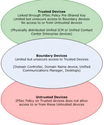
The Cisco Network Isolation Utility uses the Windows IPSec feature to isolate ICM devices (for example, the router, the logger, and the peripheral gateway device) from the rest of the network. The utility creates a Network Isolation IPSec policy, which, once deployed, sets ICM devices as Trusted and authenticates and optionally encrypts all traffic between Trusted Devices. Traffic between Trusted Devices continues to flow normally without any additional configuration. All traffic to or from devices outside the Trusted Devices is denied unless it is classified as coming from or going to a Boundary Device.
A Boundary Device is a device without an IPSec policy that is allowed access to a Trusted Device. These devices typically include the Domain Controller, the Cisco Unified
Communications Manager, default gateway devices, CTIOS desktops, WebView clients, serviceability devices, and remote access computers.
Each Trusted Device has its own list of Boundary Devices, which is defined either by separate IP addresses or subnets or ports.
The Network Isolation policy uses the IPSec ESP (Encapsulating Security Payload) protocol for integrity and encryption. The cipher suite deployed is as follows:
• IP Traffic Security:
– Integrity algorithm: SHA1 – Encryption algorithm: 3DES • Key Exchange Security:
– Integrity algorithm: SHA1
– Encryption algorithm: 3DES (optional)
Chapter 3: Applying IPSec with the Network Isolation Utility Deploying IPSec Manually Versus Deploying It Via the Network Isolation Utility
An Illustration of Network Isolation Utility Deployment
Figure 1: Example Network Isolation Deployment
How the Network Isolation Utility Works
To understand the Network Isolation Utility design and how it works, you should understand the following:
• IPSec Terminology (page 25)
• The Network Isolation Utility Process (page 26)
IPSec Terminology
• Policy
An IPSec policy is a collection of one or more rules that determine IPSec behavior. In Windows Server 2003, multiple policies can be created but only one policy can be assigned (active) at a time.
Each rule is made up of a FilterList, FilterAction, Authentication Method, TunnelSetting, and ConnectionType.
• Filter List
A set of filters that match IP packets based on source and destination IP address, protocol, and port.
• Filter Action
A filter action, identified by a Filter List, defines the security requirements for the data transmission.
• Authentication Method
An authentication method defines the requirements for how identities are verified in communications to which the associated rule applies.
For fuller definitions of Microsoft Windows IPSec terminology, see Overview of IPsec Policy Concepts (http://www.microsoft.com/technet/security/guidance/architectureanddesign/ipsec/ ipsecapa.mspx).
The Network Isolation Utility Process
The Network Isolation Utility must be run separately on each Trusted Device. Do not run the utility on Boundary Devices.
To allow traffic to or from Boundary Devices, the Boundary Devices list on each Trusted Device must be configured manually.
Once the Network Isolation IPSec policy is deployed on a device, that device is set as Trusted and traffic flows freely between it and any other Trusted Device without any additional configuration.
When run, the Network Isolation Utility does the following:
1. Removes any IPSec policies already on that computer. This is to avoid conflicts so the new policy matches on all ICM devices for a successful deployment.
2. Creates a Cisco Unified Contact Center (Network Isolation) IPSec policy in the Windows IPSec policy store.
3. Creates the following two rules for the policy:
a. Trusted Devices Rule
Trusted Devices Filter List: all traffic. One filter that matches all traffic.
Trusted Devices Filter Action: Require security. Authenticate using the integrity
algorithm SHA1 and optionally encrypt using encryption algorithm 3DES.
Chapter 3: Applying IPSec with the Network Isolation Utility How the Network Isolation Utility Works
Authentication Method: The authentication method used to create trust between
computers is a Preshared Key.
The Preshared Key can be a string of words, numbers, or characters except the double quote symbol. The minimum length for this key is 36 characters.
b. Boundary Devices Rule
Boundary Devices Filter List: (empty by default)
Boundary Devices Filter Action: Permit traffic without IPSec policy. Boundary
Devices do not require IPSec to communicate with Trusted Devices.
4. Stores a copy of the Cisco Unified Contact Center IPSec policy in an XML file located in Network Isolation utility folder:<system
drive>:\CiscoUtils\NetworkIsolation\CiscoICMIPsecConfig.XML The XML files stores the policy state and the Boundary Device list. It does not store the pre-shared key.
5. Logs all commands and actions in a log file at:
<SystemDrive>:\CiscoUtils\NetworkIsolation\Logs\CiscoICMNetworkIsolation. log
The utility keeps one copy of the log file and appends all commands and actions to any previously created logs.
About Encrypting Traffic
The Network Isolation policy allows only those computers having the same pre-shared key to interact. However, if encryption is not enabled, then, although an outside hacker cannot access a trusted computer, the hacker might be able to see the traffic coming and going from that computer. Therefore, you can also encrypt that traffic if you want to.
Note:
• You cannot encrypt traffic to one Trusted Device alone. You must either encrypt traffic on all Trusted Devices or none. The reason is that if only one computer has encrypted traffic, then none of the other Trusted Devices will understand it.
• Cisco strongly recommends the use of encryption offload network interface cards when IPSec is enabled with encryption so that performance is not impacted by the encryption software. See IPSec and NAT Support (page 11) for more details.
How to Deploy the Network Isolation Feature
• Important Deployment Tips (page 28) • Sample Deployment (page 28)
• Devices That Must Communicate with One Another (page 33) • Typical Boundary Devices (page 34)
Important Deployment Tips
No configuration is needed on Boundary Devices. All the configuration is done on Trusted Devices. The Network Isolation Utility configures Trusted Devices to interact with other Trusted Devices and with Boundary Devices.
Since the network isolation feature is applied on one device at a time, and since this feature instantly limits communication with other devices once it is applied, you need to carefully plan how to deploy this feature before using it or you could accidentally stop your network from working. It is advisable to write a deployment plan before you implement the Network Isolation feature. You should deploy this feature therefore only during a maintenance window and you should review the Caveats (page 36) before writing your deployment plan.
Sample Deployment
The following is one sample deployment. Phase one of the deployment is to deploy the policy on the ICM Router, Logger, and AW and to put the Peripheral Gateway (PG) subnets in the ICM Router's Boundary Devices list. Phase two of the deployment is to remove the PGs from the ICM Router's Boundary Device list simultaneously as the policy is deployed on the PGs.
1. Start with a fully functional Unified ICM or Cisco Unified Contact Center Enterprise system that has no IPSec policy deployment.
Chapter 3: Applying IPSec with the Network Isolation Utility How to Deploy the Network Isolation Feature
Figure 2: Example Contact Center Enterprise System
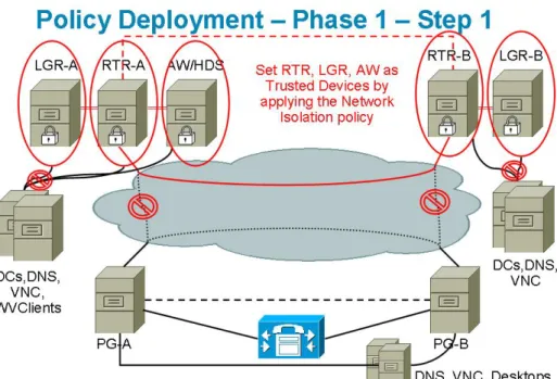
2. Set the ICM Router, the Logger, and the Admin Workstation as Trusted Devices by running the Network Isolation Utility on each of them.
Figure 3: Example Phase 1 - Step 1 IPSec Deployment
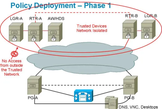
Figure 4: Example Tusted Device Isolation
3. Add the infrastructure servers and clients as Boundary Devices. Figure 5: Example Phase 1 - Step 2 IPSec Deployment
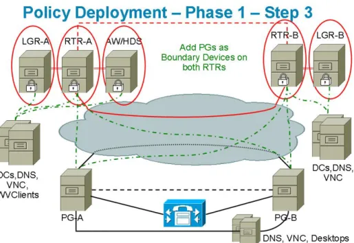
4. Put the Peripheral Gateway (PG) subnets in the ICM Router’s Boundary Devices list.
Chapter 3: Applying IPSec with the Network Isolation Utility How to Deploy the Network Isolation Feature
Figure 6: Example Phase 1 - Step 3 IPSec Deployment
5. Then set the PGs as Trusted Devices and simultaneously remove them from the Router's Boundary list.
Note: Once the policy is deployed on a PG, that PG is a Trusted Device. Therefore, it is
imperative that the PG be removed from the Router's Boundary Device list since a communication path (in this case, between the router and the PG) cannot be set as both Trusted and Boundary.
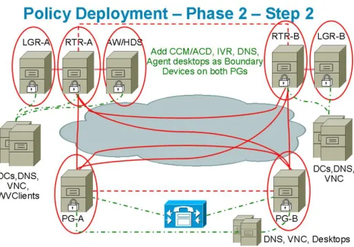
6. Add the Unified Communication Manager or ACD server, the DNS, and the agent desktops as Boundary Devices on both PGs.
Figure 8: Example Phase 2 - Step 2 IPSec Deployment
When you are finished, all ICM Trusted Devices will communicate with ONLY each other and their respective Boundary Devices (the domain controller, the DNS, the Unified Communications Manager, and so on). Any network attack from outside will not reach the Trusted Devices, unless routed through the Boundary Devices.
Figure 9: Example IPSec Deployment - Overall Design
Chapter 3: Applying IPSec with the Network Isolation Utility How to Deploy the Network Isolation Feature
Devices That Must Communicate with One Another
Each device in the following list must be able to have two-way communication with each device in its sublist. These devices can be set as either Trusted or Boundary Devices:
• Router
– Router (on the other side in a duplex system) – Logger
– Admin Workstation/ Historical Database Server – NAM Router
– Peripheral Gateway (on both sides in a duplex system) – Application Gateway
– Database Server – Network Gateway • Logger
– Historical Database Server/ Admin Workstation – Router
– Campaign Manager – Dialer
• Peripheral Gateway
– Multichannel/Multimedia Server
– Router (on both sides in a duplex system)
– Peripheral Gateway (on the other side in a duplex system) – Cisco Communications Manager
– Admin Workstation legacy PIMS/switches • CTIOS Server and CTIOS Clients
– CTIOS Server (on the other side in a duplex system) – Peripheral Gateway
– CTIOS Agent desktops – Cisco Agent Desktop – All CTI Clients • Silent Monitor Server
– CTIOS Server (on the other side in a duplex system) – Peripheral Gateway
– CTIOS Agent desktops – Cisco Agent Desktop – All CTI Clients
• Admin Workstation/Historical Database Server – Multichannel/Multimedia Server
– Router – Logger
– WebView Server
– Custom Application Server – CON API Clients
– Internet Script Editor Clients/ Webskilling – 3rd Party Clients/ SOL party
• WebView Server
– Admin Workstation/Historical Database Server – Clients
– 3rd Party Software Server – Open Software Server
Typical Boundary Devices
The following is a list of Boundary Devices that you will typically need to allow normal functioning of an ICM system:
Chapter 3: Applying IPSec with the Network Isolation Utility How to Deploy the Network Isolation Feature
• Domain Controllers for RTR, LGR, AW or HDS, and PGs
Configuration Example:
Boundary Device(s): Domain Controller IP Address(s) Traffic Direction: Outbound
Protocol: Any Port: Not Applicable
• DNS, WINS, Default Gateway
• Remote Access or Remote Management for every Trusted Device (VNC, pcAnywhere, Remote Desktop Connection, SNMP)
Configuration Example for VNC: Boundary Device(s): Any host Traffic Direction: Inbound Protocol: TCP
Port: 5900
• Communications Manager Cluster for PGs
Configuration Example:
Boundary Device(s): A specific IP Address (or Subnet) Traffic Direction: Outbound
Protocol: TCP Port: All ports • Agent Desktops
Configuration Example for CTIOS Server: Boundary Device(s): A Subnet
Traffic Direction: Inbound Protocol: TCP
Port: 42028 • WebView Clients
Configuration Example for WebView Server: Boundary Device(s): A Subnet
Traffic Direction: Inbound Protocol: TCP
Port: 80 and 443
The Support Tools 2.1 or greater server does not need to be added to the Boundary Server list if its policy has the same preshared key as the policy created by the Network Isolation Utility.
Caveats
You must carefully plan deployments so that the policy is applied to all machines at the same time. Otherwise, you can accidentally isolate a device.
• Important: Enabling the policy remotely will block remote access unless a provision is made
in the Boundary Device list for remote access. You must add a Boundary Device for remote access before enabling the policy remotely.
• Important: You must add all domain controllers as Boundary Devices or your domain login
will fail and your ICM services will also fail to start or you may see delayed login times. This list of domain controllers should include all domains in which the ICM application is installed as well as all domains in which ICM setup, configuration and Webview users and supervisors exist.
• Adding a new device as Boundary Device (for example, a new Domain Controller) requires a change to the policy on all Trusted Devices which need access to this new device without IPSec.
• A change in the Preshared Key must be invoked on all Trusted Devices.
• If you enable encryption on only one Trusted Device, then that device will not be able to communicate with the other Trusted Devices since it's network traffic will be encrypted. Encryption should be enabled on all or none of the Trusted Devices.
• You should avoid the use the Windows IPSec Policy MMC plug-in to make any changes to the IPSec policy. The Network Isolation utility maintains its own copy of the policy, and, whenever executed, the utility reverts to its last saved configuration, ignoring any changes made outside the utility (or the Security Wizard).
• When you install the Cisco Support Tools, 2.1 or later on a device, an IPsec policy is automatically applied to that device. If you then run the Network Isolation Utility on that same device, the Support Tools IPSec policy will be deleted and replaced by the Network Isolation IPSec policy.
Chapter 3: Applying IPSec with the Network Isolation Utility Caveats
The Cisco Unified Contact Center (Network Isolation) IPSec policy supercedes the Cisco Unified Contact Center (Support Tools) IPSec policy. This means that the Support Tools Installation will not overwrite or modify the Network Isolation IPSec policy.
As long as the preshared key is the same for all the Trusted Devices and the Support Tools server, the Support Tools server will continue to work and connect to the Support Tools Node Agents on the Trusted Devices using IPSec.
• While the Network Isolation Utility does not interfere with applications that run on the network, it should be run only during the application maintenance window since it can potentially disrupt connectivity when you are setting up the network security.
• If your network is behind a firewall, then you must configure the firewall to:
– Allow IP protocol number 50, which is the ESP (Encapsulating Security Protocol). – Allow UDP source and destination traffic on port 500 for the IKE (Internet Key Exchange)
protocol.
• If you are using the NAT (Network Address Translation) protocol, then you must configure the firewall to forward traffic on UDP source and destination port 4500 for UDP-ESP encapsulation.
• Any changes made to the application port usage, such as a web server port, must also be reflected in the policy.
• The Network Isolation Policy should be deployed after the ICM or the Unified Contact Center application is configured and confirmed to be working.
How to Do a Batch Deployment
You can use the XML file (<system
drive>:\CiscoUtils\NetworkIsolation\CiscoICMIPsecConfig.XML ), containing the list of Boundary Devices and policy state, on one Trusted Device to replicate the policy on other Trusted Devices. This can help to speed up deployment when a common set of Boundary Devices must be added to all Trusted Devices.
For example, when setting up your PGs as Trusted Devices, you may first want to complete configuring one ICM PG. Next, you can copy the XML file from that configured PG to the rest of your ICM PGs, and then run the Isolation Utility (or the Security Wizard) on the other PGs to replicate the same Boundary Device list on all your PGs.
How to Run the Network Isolation Utility from the Command Line
You can run the Network Isolation Utility either from the command line or from the Unified Contact Center Security Wizard.
Note: It is recommended that you use the Security Wizard for initial policy creation or
modification. You can use the command line for batch deployment.
To run the utility from the command line, go to the C:\CiscoUtils\NetworkIsolation directory, where the utility is located, and run it from there:
C:\CiscoUtils\NetworkIsolation>
The following is the command-line syntax for enabling the policy on Trusted Devices:
cscript ICMNetworkIsolation.vbe <arguments>
Note: You must use cscript to invoke the script.
You can add Boundary Devices with multiple filters. You can filter them by: • IP Address: Individual IP addresses or by an entire subnet of devices
• Dynamically detected devices: DNS, WINS, DHCP, Default Gateway
Windows dynamically detects the IP address of these devices and keeps the filter list updated • Direction of traffic: inbound or outbound
• Protocol: TCP, UDP, ICMP, or any protocol
• Port (only if TCP or UDP is selected): a specific port or all ports
In the syntax:
• angle brackets < > = required • square brackets [ ] = optional
• a pipe or bar | = any one of the items between the bar(s)
The following table lists the command syntax for all uses of the command.
Table 1: The Network Isolation Utility Command Syntax for Each Argument
Function Syntax and Example
Argument Name
Displays the syntax for the command. cscript ICMNetworkIsolation.vbe /?
HELP
ENABLE POLICY Creates a new policy or enables an existing one
from the stored policy XML file. cscript ICMNetworkIsolation.vbe /enablePolicy
<36+ characters PreSharedKey in double quotes> [/encrypt]
Optionally enables encryption of the network traffic data.
Note: The only non-supported character for use
in the PresharedKey is double quotes since that
Creates a new policy in Windows IPSec policy store and adds all Boundary Devices listed in character marks the beginning and end of the key.
You can enter any other character within the key.
Chapter 3: Applying IPSec with the Network Isolation Utility How to Run the Network Isolation Utility from the Command Line