O R I G I N A L R E S E A R C H
Open Access
A new coordinated backup protection
scheme for distribution network containing
distributed generation
Jinghan He, Lin Liu, Fanfan Ding
*, Changcheng Li and Dahai Zhang
Abstract
This paper proposes a new backup protection scheme, named coordinated backup protection (CBP) scheme, for distribution networks containing distributed generation. The proposed protection scheme takes into account the issues faced by traditional backup protection, such as difficulty in setting parameters and complex cooperation, and considers the features of distribution networks, such as changeable power flow because of high penetration of distributed generation sources and insufficient measuring quantities. The CBP scheme includes two aspects: coordinated substation protection and regional master substation protection, who also work as nearby backup protection and remote backup protection respectively. The two protections support each other by local information coordination and regional information sharing, in order to improve the reliability of fault identification. The configuration principles and performances of the proposed backup protection scheme are addressed in the paper. Different fault conditions in the IEEE 14-node system have been used to illustrate and verify the feasibility of the CBP scheme.
Keywords:Distribution network, Backup protection, IEC61850, Tabu search
1 Introduction
Modern power systems are facing great challenges due to the deregulation of the electricity market, environmen-tal concerns and energy policy change. With a number of major blackouts occurred around the world, customers’ expectation of system reliability and power quality has also gradually increased. The growth of renewables as energy source has promoted the development of distributed generation [1, 2]. However, traditional electrical infrastruc-ture cannot satisfy these development requirements, and thus a new grid infrastructure is urgently needed. To ad-dress the challenges facing the existing power grid, the new concept of smart grid has emerged [3, 4].
With the wide spread application of intelligent elec-tronic devices (IEDs), information digitization and the IEC61850 protocol, the development of protection using comprehensive information is greatly impelled. Extensive studies have been carried out by researchers on how to improve the protection performance and functionalities by better utilization of digital and communication
technologies. From the division of protection informa-tion domain, wide area protecinforma-tion is based on wide area measurement system (WAMS) to implement large-scale system protection and control [4–9]. This kind of system is developed from early special protection systems (SPS) [10] and broadens traditional relay protection function from point to surface. Narrow-sense wide area protec-tion is a system level protecprotec-tion aimed at reflecting vari-ous system disturbances through analyzing power system wide area information and evaluating system states. This kind of protection has better sensitivity and effectiveness compared with traditional SPS [11]. Gener-alized wide area protection including wide area relay protection (WARP) helps to assist main protection to improve adaptability, simplify cooperation strategy and shorten action time [12]. At present, because of the communication delays, wide area protection is mainly applied to the backup protection and integral control of large-scale gird. On the other hand, protection systems whose information domain is within a substation or within a local area network have been proposed. These protection schemes analyze the integrated information and make use of adaptive setting principle to realize * Correspondence:[email protected]
School of Electrical Engineering, Beijing Jiaotong University, Beijing 100044, China
comprehensive relay protection. Integrated protection (IP) (as in [13] and [14]) integrates all the information from a digital substation into one computer system to form a reliable, flexible and complementary integrated protection system. Integrated network protection (INP) is based on IP but its information range is extended to several correlative substations. There are some other protections that use similar concept, referred to as aggre-gate protection (AP) which uses other relays’information to improve its own protection performance, centralized protection [15], and protection based on multi-sources [16]. All these studies have driven the protection and con-trol system to utilize comprehensive information to achieve better performance and to satisfy modern grids’ functional requirements. Compared with traditional pro-tection, there have been marked improvements.
Studies above indicate that protection based on comprehensive information can adapt to power net-work development. Current researches mainly focus on analyzing integrated comprehensive data whereas pro-tection considering coordination of different units and functions needs further study. Moreover, comprehen-sive data depends on global information acquisition. However, the network states are sometimes immeasur-able and only partial information is availimmeasur-able from the distribution network in practice, especially the node voltage information. Thus the protection unit can only get information of several important nodes and it is a challenge to propose protection strategy based on in-sufficient measuring quantities.
This paper proposes a solution to the above issues. Retaining the information acquisition mode and com-munication network of smart grid, this paper presents a coordinated backup protection (CBP) scheme and corre-sponding protection configuration principles. It includes coordinated substation protection and regional master substation protection. Coordinated substation protection pays more attentions to the coordination and cooper-ation among different IEDs and substcooper-ations, and works as the nearby backup protection. Compared to the existing protection schemes, distributed IED has advantages in terms of functional support, information utilization, and achieving higher protection reliability. Master substation protection mainly analyzes regional comprehensive infor-mation and works as the remote backup protection. Con-sidering the likelihood of insufficient state measurements, an integrated MS protection based on centralized searching method is proposed in master substation protection.
In this paper, an introduction on the framework of CBP scheme is presented in Framework of coordination backup protection scheme section. Protection principles section depicts the configuration of CBP and its princi-ples are discussed in details. Case studies are carried out
in Test and results section to prove the reliability and ef-fectiveness. Finally, Conclusion section draws conclusions.
2 Framework of coordination backup protection scheme
The CBP scheme includes coordinated substation (CS) protection and regional master substation (MS) protection who also work as nearby backup protection and remote backup protection, respectively. The two protections sup-port each other by local information coordination and re-gional information sharing, in order to improve the reliability of fault identification. Compared with traditional backup protection scheme, the CBP scheme has stronger independence and higher reliability, and at the same time, the cooperation between CS protection and MS protec-tion helps to decrease the risk of protecprotec-tion malfuncprotec-tion.
2.1 Coordinated substation (CS) protection
The CS is an application concept that uses the unified communication protocol and strong information net-work of smart grid, and at process level, accomplishes synchronous sample value acquisition, action command execution and breaker states uploading. Based on the needed local information, bay level includes a number of protection IEDs to implement protection. At the same time, modularization structure of IED helps in harmoni-ous interaction and coordination of functions to support reliable fault identification which is independent to backup protection. The coordination of IEDs includes information sharing, redundant CPU space utilization and coordinated backup tripping. Station level is the top one which integrates useful data and events for substation management and communication with dispatching center or MS.
paper, installation of the IEDs is in the standard bay as in traditional protection devices and the IEDs are based on block-based design principle which makes it easy to recombine or extend functions through standard module interface.
CS protection is a distributed substation-domain pro-tection, and its protection range is the elements within the substation and outgoing-lines. Some coordinated IEDs implement local rapid protection judgment and other IEDs exchange information with adjacent substa-tions for protection judgment of the outgoing-lines. If primary equipment (CT/VT/CB) is in abnormal working states, IEDs work in coordination mode and their data sharing and coordinated tripping help to improve the re-liability of local substation protection.
2.2 Master substation (MS) protection
MS protection is a regional integrated backup protection (RIBP) and its protection range is the network composed of several CSs. The RIBP acquires every CS’s available data through wide area communication network to analyze re-gional comprehensive information. Likewise, if primary equipment (CT/VT/CB) is in abnormal working states, RIBP can acquire valid data through coordinated informa-tion analysis in corresponding CS. For power systems up to 110 kV, the protection scheme usually consists of single main protection and has no breaker failure protection [18]. The RIBP can help to realize dual-configuration pro-tection and improve reliability. In addition, backup protec-tion based on wide area informaprotec-tion optimizes general
backup protection in action time while still ensuring reliability.
RIBP of MS parses the data packages and integrates all the regional information. By analyzing the integrated data, the protection algorithm unit calculates and out-puts fault judgment results. Output tripping signals are sent back to communication network to reach the corre-sponding objective CS. Station level of CS obtains the tripping signals and relative IED in process level sends the tripping command to intelligent units (IU) and cir-cuit breakers (CB) to isolate fault.
2.3 Communication network
In order to implement the CBP scheme, communication network is one of the key technologies. The CBP com-munication system includes three parts: process level communication network within CS, network communi-cated with adjacent substations, MS integrated data communication network.
Process level communication network within CS is shown in Fig. 1. Based on the IEC61850-9-2LE standard, the communication between bay level and process level is via high performance local area network (LAN) [7] which is the process bus (SV + GOOSE). Considering large quantities of information and network load cap-acity, dual process network is set in CS (shown in Fig. 1). The function module which is the protection calculation part communicates with primary equipment through LAN“SV + GOOSE A”. The coordination part, including LCM and RCM, communicates with the same part from other IEDs through LAN “SV + GOOSE B”. In order to synchronize different data sources, LAN communication needs have accurate GPS synchronous time-marker.
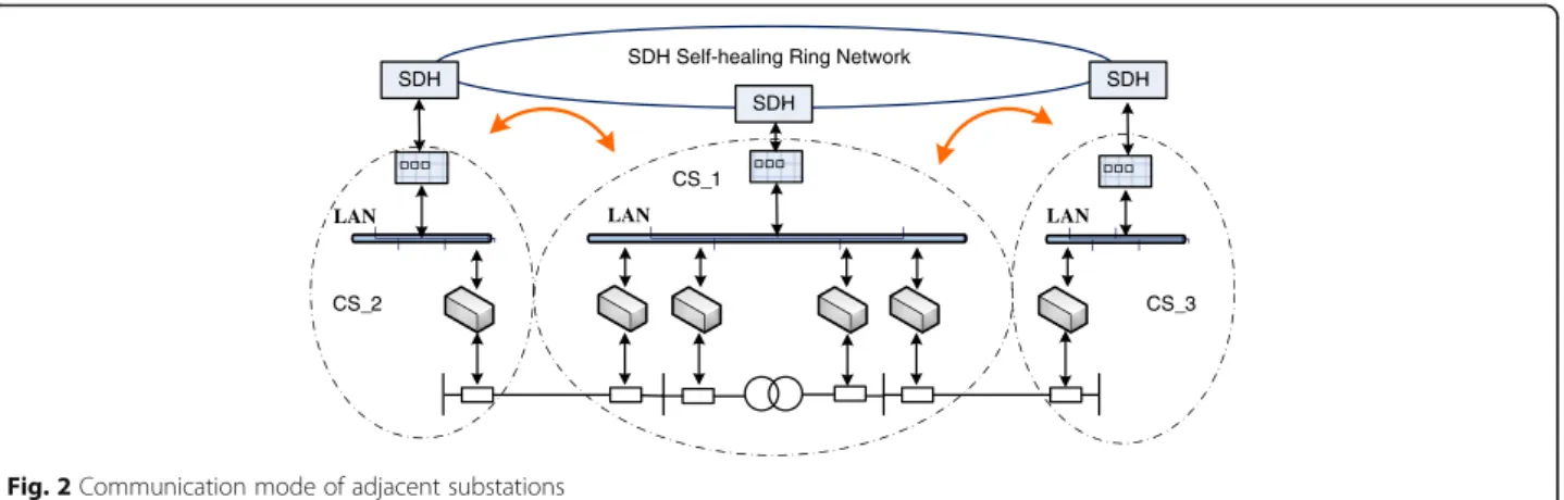
One CS can exchange information of outgoing-lines with adjacent substations to implement cooperation work among different substations. Network communi-cated with adjacent substations uses synchronous digital hierarchy (SDH) [19] technology and works in self-healing ring transmission mode. The CSs and MS con-nect with each other in a ring and flexible data acquisi-tion is available. As shown in Fig. 2, CS_2 and CS_3 upload data to SDH network by SDH device, and CS_1 can download the necessary data from SDH network for CS substation-domain protection judgment.
Because the quantity of multi-CS transmission data is large and communication has high real-time require-ment, MS integrated data communication network also uses SDH technology as special communication network of wide area protection (shown in Fig. 3). As communi-cation network terminals, CS accomplishes local protec-tion judgment and at the same time, its IEDs preprocess the sample values and package necessary data. For those data that needs to be synchronized, unified GPS syn-chronous time-marker should be tagged to packaged
message. All the shared data is uploaded to SDH net-work through SDH method, and MS could download the needed data from the network. Computer simulation shows that SDH fiber communication network can satisfy transmission delay requirements of WARP [19].
The latency is another concern, which includes the sen-sor delay (5 ms), communication delay, processen-sor compu-tational time (dependent on the protection principle), and circuit breaker operation time (90 ms). The communica-tion delay of the process level is about 5μs which is negli-gible, whereas the possible longest communication delay of wide-area optic fiber network is 24 ms. For regional dis-tribution networks, the communication delay will not be longer than 24 ms. Therefore, the protection principle should ensure the calculation to be carried out efficiently in order to isolate fault as soon as possible.
3 Methods
CS protection implements local rapid fault judgment and coordination working mode and can help to improve protection reliability. MS integrated backup protection, which is known as RIBP in previous discussion, analyzes regional comprehensive information to recognize fault ef-fectively in case CS protection fails to clear the fault.
The following discusses the detailed CS protection and MS protection configuration principles.
3.1 CS protection based on differential principle
The principle of current differential protection is not af-fected by changeable power flow. Therefore, this type of protection can identify faults correctly and rapidly with-out the need for VTs at every node to provide direction-ality. In CS protection, differential principle is applied and multiple IEDs can cooperate by information sharing and function coordination to implement extended dif-ferential protection. The basic principle is to use the nearest non-fault data when local data has failure and to broaden trip boundary when protection or breaker does not operate correctly.
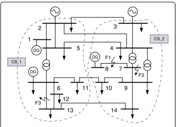
Based on the CS concept in Framework of coordin-ation backup protection scheme section, the IEEE 14-node system is divided into two substations (CS_1 and CS_2) in Fig. 4, and the two CSs dispose substation do-main protection separately based on differential principle. As an example, fault 1 (F1) in the IEEE 14-node system as shown in Fig. 4 is considered and the coordination working mode is analyzed. In this paper, positive current direction is defined as from bus to the line. I_471, I_781 and _
I791 are the first-terminal currents of line4-7, line7-8 and
line 7–9, respectively. I_472, I_782 and I_792 are the
second-terminal currents of the same three lines, respectively. The basic differential current dif1 of line 7–8 is
_
I781þI_782
. If the local data I_781 has failure, it can be Fig. 2Communication mode of adjacent substations
replaced by I_472 and I_791 through information
coordin-ation with other IEDs. The informcoordin-ation sharing is achieved through the process bus LAN“SV + GOOSE B”, and the differential current dif2 should change to
_
I782− I_472þI_791
. Furthermore, the differential current dif3can also be expressed by replacing I_472 with I_471.as
_
I782−I_791þI_471
.
3.2 MS protection based on centralized searching method
For a large-scale network, only some key nodes have PMU measurements due to the cost. In general, those key buses and buses having several feeders should be regarded as the key nodes. As DG node voltages are ne-cessary for their converter control and condition moni-toring, the DG nodes should also be the key nodes.
When there is a fault in the network, node voltages have no directionality according to fault sequence ana-lysis. This is because that voltage drops occur at the nodes at or around the fault and low voltage protections will all act. The fault point has the lowest voltage and voltage increases with the increase of the electrical dis-tance. Thus voltage information can reflect fault location to some extends, though when voltage data is only avail-able at the key nodes, it is difficult to diagnose the fault. Obviously, when there is a fault, most power from the power sources will go to the fault point through a mini-mum impedance path, referred to as the fault power path in this paper. The fault power flow of this path is the biggest and direction is to the fault point. Based on the selection of the fault power path and search tree model, together with current information comparison, fault location can be identified effectively. Thus this paper proposes a MS protection based on centralized searching method, and based on that backup protection can be realized.
The key nodes sequence from initial results are searched and the node with the maximum objective function value (Z* shown in formula 1) is found to be the fault power path. The termination condition isc≥(k+p+ 1) wherek andpare the number of general key nodes and DG nodes respectively.
Z¼Z xð Þ ¼ X
j
re U_iI_i:j
−X
j
re U_i:loadI_i:j:load
c¼cþ1
s:t:re U_iI_i:j
<0&re U_i:loadI_i:j:load
<0
c0¼0
8 > > > > < > > > > :
ð1Þ
Where,
x∗: feasible solution
_
Ui: voltage vector of node i
_
Ii:j: current vector of the line between node i and j
_
Ui:load: voltage vector of node i (normal operation)
_
Ii:j:load: current vector of the line between node i and j
(normal operation)
re[ ]: calculation of real component c: iteration counter
The second-step search appoints fault power path as the search target and works to find the fault using current information.
➀ When it is a node fault, voltage at the fault point is approximately zero and the vector sum of the node cur-rents is not zero based on Kirchhoff’s current law. The features discussed above can be used to judge node fault. ➁When it is a branch fault, the fault current flows through non-fault branches which is the same as load current. For the fault branch, the contralateral line current is zero if it is a single-terminal power network. On the contrary, if it is a double-terminal power net-work, the contralateral line current is positive but the direction information is hard to calculate due to the lack of voltage data. Thus, a fault criterion based on current data for double-terminal power network is necessary.
Neglect the line charging capacitance and system im-pedance, line impedance and generator transient react-ance are inductive. In this paper, phase angle change is defined as the absolute value between the positive se-quence component of the fault current and the non-fault current. For the non-non-fault branch, the phase angle changes of the two terminals are small whereas for the fault branch, the phase angle change of one terminal is small but the other is large. Thus the fault criterions based on current information are given as
arg _I_Kð Þ1:i
Inormal:i
!
− arg
_ IKð Þ1:j _ Inormal:j
!
>Arel ð2Þ
where, Arel is around 5∘~ 10∘. The branch, whose
two-terminal current data satisfies either criterion, can be judged as the fault line. In this paper, the cri-terion is named as two-terminal current phase com-parison (TCPC) criterion for line protection. The criterion needs no voltage data and fault judgment is independent from directional element.
If the line is connected with single-terminal power sys-tem, the second-terminal current of the feeder line is compared with unbalanced current to judge whether it is a line fault. If the line is connected with two-side power system, line fault is judged by the TCPC criterion. The second-terminal node is judged by bus differential criterion to decide whether it is the fault node.
3.3 Time coordination analysis
CS protection judges fault independently and coordin-ation of informcoordin-ation and functions helps to trip reliably. The two-step search of MS protection needs small cal-culation time, and thus the tripping output works with minimum delay. When the CS protection has judgment failure, backup protection will operate. However, if CS protection needs coordination among many IEDs, time required for communication and coordinated judgment will be long and tripping output time may be longer than that of the backup protection. In that case, the backup protection should output tripping signals imme-diately in order to clear the fault.
4 Results
A test case using the IEEE 14-node network (shown in Fig. 3) is simulated to evaluate the performance of the CBP scheme. The IEEE 14-node network is a complex radial network with 3 DGs. There are current trans-formers (CT) at both terminals of the lines and only the key nodes have voltage transformers (VT). As the net-work is complex, markings of the CT/VTs are omitted in Fig. 3. In this paper, it defines that VT is named by the node number, and CT is named by the two-terminal nodes and location terminal. For instance,U4is the
volt-age of node 4,I471is the current of line 4–7 at the node
4 terminal, andI472is the current of line 4–7 at the node
7 terminal. Set 1, 4, 5, 6, 8 nodes as the key nodes and the fault inception is at 0.3 s. Simulations are performed using MATLAB. Measurement data is based on the re-sults of power flow analysis and Gaussian random num-ber (expectation is zero and variance is 0.01) is superimposed as measurement error.
4.1 Fault 1
An ABC fault is applied at line 7–8 (fault 1). According to the coordinated differential protection discussed in Protection principles section the three differential cur-rents (dif1,dif2,dif3) are calculated.
0 0.2 0.4 0.6 0.8 1 1.2 1.4 0
0.5 1 1.5 2 2.5 3
Res(kA)
Di
f(
k
A
)
dif1 dif2 dif3 setting value
Fig. 5Differential currents with F1
Table 1Voltage amplitude and objection function values of key
nodes (Fault 1)
Node 1 (DG) 4 5 6 (DG) 8 (DG)
ABC Voltage Amplitude (kV) 98.92 5.62 68.98 64.69 127.02
Z∗ (MW)
3.25 11.86 1.14 −9.85 0
0.250 0.26 0.27 0.28 0.29 0.3 0.31 0.32 0.33 0.34 0.35 20
40 60 80 100 120
Time(s)
C
ur
rent
P
has
es
C
hange (
degr
ees
)
I471 I472 I781 I782
Fig. 6Current phase changes of fault power path (F1 and ABC)
Table 2Evaluation data and result (portion) Current phase
changes of fault power path (Fault 1)
Fault type
Positive sequence current phase change of A phase (degrees)
|Δφ471| |Δφ472| |Δφ781| |Δφ782|
ABC 0.5637 0.5358 0.7231 107.1168
A to G 0.2223 0.2272 0.3313 105.9737
AB 0.1407 0.1495 0.2447 108.1144
AB to G 0.3501 0.3985 0.2281 106.8386
BC 0.1908 0.1366 0.2761 108.1041
Figure 5 shows the calculation results, and it can be seen that the differential currents increase significantly after fault occurrence. It is obvious that, differential pro-tection using information sharing can judge the fault ef-fectively. From the partial enlarged waveforms shown in Fig. 5, differential currentdif2anddif3have larger
unbal-ance currents compared withdif1. The reason is that
in-formation coordination brings greater measurement error and distributed capacitance current [20]. In real application, the unbalance current can be significant considering IED communication error and data conver-sion error. Thus, in order to maintain reliability, protec-tion setting should consider the effect of informaprotec-tion sharing and coordination.
The MS protection based on centralized searching method is applied in the same simulation case. The volt-age amplitudes and first-search objection function values are shown in Table 1. The key nodes by voltage ampli-tudes are sorted and node 4 has the lowest value. The key nodes are searched from node 4 and the maximum objection function value is found to be at node 4. Thus the fault power path is from node 4 which is then set as the beginning node for the second-step search. The phase angle changes of the fault power path are calcu-lated and the two terminal phase angle changes of one line are compared to judge the fault.
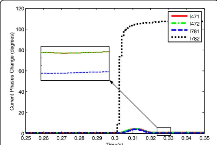
Figure 6 shows the current phase changes of the fault power path. After the fault occurrence at 0.3 s, the phase changes ofI471and I472are almost identical but the sum
of the phase changes of I781 and I782 is about 108∘.
Judged by the criterion in Test and results section, the fault is on line 7–8 (fault 1).
In order to further analyze the accuracy of the criion, several typical fault types are tested and the two ter-minal phase angle changes are compared. Table 2 shows the current phase changes. Obviously, the fault criterion can judge different faults accurately.
4.2 Fault 2
An ABC fault is applied at node 7 (fault 2). As the main protection based on differential principle is simple and reliable, this case only analyzes the MS protection based on centralized searching method.
The voltage amplitudes and first-search objection function values are shown in Table 3. The key nodes by voltage amplitudes are sorted and node 4 has the lowest value. The key nodes from node 4 are then searched and the maximum objection function value is found to be at node 4. Thus the fault power path is from node 4 and it is the beginning node of the second-step search.
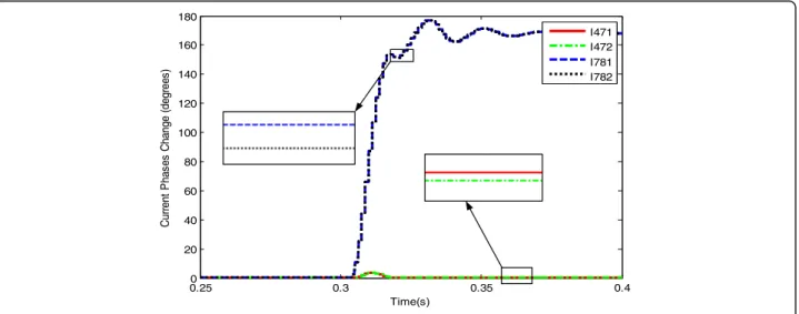
The phase angle changes of the fault power path are calculated and the two terminal phase angle changes of one line are compared to judge the fault. Figure 7 shows the current phase changes of the fault power path. After fault occurrence at 0.3 s, phase changes ofI471and I472
are almost identical and so as for I781andI782. The line
fault criterion is not satisfied and thus it can be con-cluded that there is no fault in lines 4–7 and 7–8. Ac-cording to the second search, the currents sum of the second terminal of line 4–7 is calculated and the result is shown in Fig. 8.
The result in Fig. 8 shows that the node differential current increases when fault occurs at 0.3 s. Thus it can be identified that the second terminal of line 4–7 is the fault location and it is a node fault.
Table 3Voltage amplitude and objection function values of key
nodes (Fault 2)
Node 1 (DG) 4 5 6 (DG) 8 (DG)
ABC Voltage Amplitude (kV) 98.44 3.79 68.09 63.74 127.02
Z∗ (MW)
2.52 7.40 −1.63 −9.92 0
0.25 0.3 0.35 0.4
0 20 40 60 80 100 120 140 160 180
Time(s)
C
ur
rent
P
has
es
C
hange (
degr
ees
)
I471 I472 I781 I782
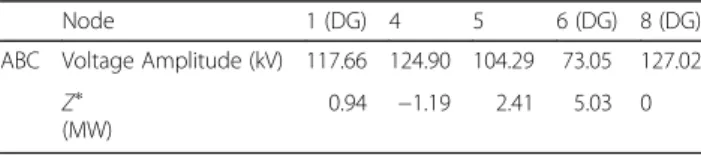
4.3 Fault 3
An ABC fault is applied at line 6–13 (fault 3). This case also analyzes the MS protection based on centralized searching method only.
The voltage amplitudes and first-search objection function values are shown in Table 4. The key nodes by voltage amplitudes are searched and node 6 has the low-est value. The key nodes from node 6 are searched and the maximum objection function value is found to be at node 6. Thus the fault power path is from node 6 and it is the beginning node of the second-step search. The phase angle changes of the fault power path are calcu-lated and the two terminal phase angle changes of one line are compared to judge the fault.
Figure 9 shows the current phase changes of the fault power path. After fault occurrence at 0.3 s, the sum of the phase changes ofI6131andI6132is about 122∘. Judged
by the criterion in Test and results section, the fault is identified to be on the line 6–13 which is fault 3.
5 Discussion
This paper presents the concept of coordinated backup protection in order to solve the issues brought by trad-itional backup protection and adapt to the changes of distribution networks. The framework is discussed in-cluding coordinated substation backup protection and regional master substation backup protection, working as nearby and remote backup protection respectively. The cooperation of the two backup protections contrib-utes to CBP’s higher reliability and better adaptability. The communication network of CBP is fully explored in
the likely scenarios, including network within substation, and communication network among adjacent substa-tions and master substation.
6 Conclusions
The configuration principles of CBP consider the changeable power flow and insufficient measuring quan-tities in distribution networks. CS protection is based on current differential principle and its coordination en-sures the reliability of nearby backup protection. MS protection is based on centralized searching protection principle which analyzes integrated regional comprehen-sive information.
From the simulation tests and results, the CBP scheme can be seen as an effective and promising solution for distribution network backup protection optimization. The strong independence and high reliability of CBP can help decrease the risk of protection malfunction.
Acknowledgement
This work is supported in part by State High-Tech Development Plan (No. 2015AA050101) and the Fundamental Research Funds for the Central Universities (No.2015YJS158).
Authors’contributions
JH contributed to the study design and analysis and drafted the manuscript; LL was involved in data acquisition, analysis and revision of the manuscript; FD worked on aspects of the study relating to inter-substation information protection system; CL was involved in data acquisition and revision of the manuscript; DZ contributed to the revision of the manuscript. All authors have read and approved the final manuscript.
Competing interests
The authors declare that they have no competing interests.
Received: 20 January 2017 Accepted: 13 March 2017
References
1. R. D. Masiello, R. D. Willoughby. PJM Roadmap: Network operations and transmission planning [EB/OL]. [2007-01-09]. http://www2.pjm.com/library.aspx. 2. Vadari, M. (2006). Demystifying intelligent networks.Public Utilities Fortnightly,
145(11), 61–64.
3. Gungor, V. C., Lu, B., & Hancke, G. P. (2010). Opportunities and challenges of wireless sensor networks in smart grid.IEEE Transactions on Industrial Electronics, 57(no.10), 3557–3564.
0.2 0.22 0.24 0.26 0.28 0.3 0.32 0.34 0.36 0.38 0.4 0
0.5 1 1.5 2 2.5 3 3.5 4
Time(s)
c
u
rre
n
t s
u
m
(k
A
)
CurrentSum
Fig. 8Current sum (F2 and ABC)
Table 4Voltage amplitude and objection function values of key
nodes (Fault 3)
Node 1 (DG) 4 5 6 (DG) 8 (DG)
ABC Voltage Amplitude (kV) 117.66 124.90 104.29 73.05 127.02
Z∗ (MW)
0.94 −1.19 2.41 5.03 0
0.250 0.3 0.35 0.4
20 40 60 80 100 120 140 160 180
Time(s)
C
ur
rent
P
has
es
C
hange (
degr
ees
)
I6131 I6132
4. Siano, P., Cecati, C., Citro, C., & Siano, P. (2011). Smart operation of wind turbines and diesel generators according to economic criteria.IEEE Transactions on Industrial Electronics, 58(no.10), 4514–4525.
5. Z. H. Jiang, F. X. Li, W. Qiao, H. B. Sun, Member, J. H. Wang, Y. Xia, Z. Xu and P. Zhang,“A Vision of Smart Transmission Grids,”PES′09 IEEE Power & Energy Society General Meeting, 2009, 26–30 July 2009, pp.1-10.
6. L. Chen, K. J. Zhang, Y. J. Xia and G. Hu,“Study on the substation area backup protection in smart substation,”Power and Energy Engineering Conference (APPEEC), 2012 Asia-Pacific, 27–29 March 2012. pp.1-4. 7. Li, Z. X., Yin, X. G., Zhang, Z., & He, Z. Q. (2013). Wide-area protection fault
identification algorithm based on multi-information fusion.IEEE Transactions on Power Delivery, 28, 1348–1355.
8. Serizawa, Y, Tanaka T, Fujikawa, F, Sugiura, H, Shioyama, T, Kimura, Y“Use case study on a decentralized modular device network for wide-area monitoring, protection and control,”2012 IEEE Power and Energy Society General Meeting, 22–26 July 2012.
9. Su, S., Li, K. K., & Chan, W. L. (2010). Adaptive agent-based wide-area current differential protection system.IEEE Transactions on Industry Applications, 46(5), 2111–2117.
10. Abdulhadi, I, Coffele, F, Dysko, A, Booth, C, Burt, G“Adaptive protection architecture for the smart grid”, 2011 2nd Innovative Smart Grid Technologies (ISGT Europe), 5–7 December 2011. pp.1-8.
11. Ingelsson, B., Sweden, S. K., Lindstrom, P. O., Karlsson, D., & Runvik, G. (1997). Wide-area protection against voltage collapse.Computer Applications in Power, IEEE., 10(4), 30–35.
12. Begovic, M., Novosel, D., & Karlsson, D. (2005). Wide-area protection and emergency control.Proceedings of the IEEE, 5, 876–89l.
13. J. Li; J. H. He; H. Zhang; F. X. Xie,“Research on adaptive protection based on integrated protection”, 2011 International Conference on Advanced Power System Automation and Protection (APAP), 2011, 848–852.
14. Zhang, H, He, JH“Design of a real-time substation communication system for integrated protection”, Transmission and Distribution Conference and Exposition, Latin America, 2008.IEEE/PES. 2008.
15. Bo, ZQ, Han, M, Klimek, A, Zhang, BH, He, JH, Dong, XZ“A centralized protection scheme based on combined positional protection techniques”, Power & Energy Society General Meeting, 2009, 1–6.
16. Xia, K. Q., Chen, G. J., Li, L., Huang, W., Song, F. H., & Wu, C. Y. (2000). DSP-based multi-information identification system for controlling harmonic in power system protection.Power Engineering Society Winter Meeting IEEE, 3, 1844–1848.
17. Watanabe, H, Shuto, I, Igarashi, K, Beaumont, P, Okuno, K“An enhanced decentralised numerical busbar protection relay utilising instantaneous current values from high speed sampling”, Seventh International Conference on Developments in Power System Protection, (IEE), 2001, 133–136. 18. He, JL (2010). Power System Relay Protection Principle, edition IV.
Beijing: China Electric Power Press, p. 387.
19. Lin, X. N., Li, Z. T., & Wu, K. C. (2009). Principles and implementations of hierarchical region defensive systems of power grid.IEEE Transactions on Power Delivery, 24(1), 30–37.
20. Glover, F., & Laguna, M. (1997).Tabu search. Boston: Kluwer Academic Publishers.
Submit your manuscript to a
journal and benefi t from:
7Convenient online submission
7Rigorous peer review
7Immediate publication on acceptance
7Open access: articles freely available online
7High visibility within the fi eld
7Retaining the copyright to your article