1980, Vol. 11, pp. 45-62
0031-2460/80/1101-0045 $06.50/0
Printed in U.S.A.
HIGH-MODULATION ELECTRON BEAMS
IN STORAGE RINGS
PAUL L. CSONKA
Institute ofTheoretical Science, University ofOregon, Eugene, Oregon 97403
U.S.A.
(Received June15, 1979; in final form August 13, 1979)Electron beams whose densitypchanges (is modulated) rapidly as a function of positionzalong the orbit are generally desirable for coherence and correlation experiments. Whenp(z)changes significantly within an optical wavelength or less, and if the number of electrons within azintervalqf this wavelength isn
»
1, the radiation emitted will differ importantly from radiation emitted by more usual beams: the angular spread will decrease (brightness will increase), the total intensity will increase by a factor of approximately n (including the x-ray region), certain wavelengths may be suppressed, and high time-resolution measurements are facilitated. Applications suggest themselves to holography, x-ray lasers, free electron lasers, etc. A method is described whereby high beam-density modulation can be induced in a storage ring with an optical laser of modest power, and the energy spread of the circulating beam is further reduced by compensation.I. INTRODUCTION
Electromagnetic radiation from electron storage rings is usually produced in short bursts lasting about 10-9to 10-10seconds. This rapid time varia-tion of the emitted radiavaria-tion proves to be of great value. Exploiting it, one can increase the signal-to-noise ratio, improve the accuracy of decay time measurements, and so forth.
The value of rapid intensity variation can be traced to the fact that the intensity as a function of
timeI(t)
is rich in Fourier components. Indeed, ifthe radiation is emitted in bursts which last a timer,I(t)has Fourier components F(w) with appreciable amplitude uJ? to circular frequenciesw
=
21TT-1,upto about10 to lOllsec-Ifor most electron storage rings. The presence of rapidly time-varying Fourier components inI(t)is in turn caused by the richness in Fourier components of the circulating electron density, p,as a function of
z,
wherez
measures the position along the trajectory: The radiation intensity depends on the density of electrons passing before the port at the moment of emission. Since all electrons travel with velocityv
~c,
presence of a Fourier component inp,which varies as exp[i2rrz/Am],
will cause the appearance of a Fourier compo-nent inI(t),
withw~2rrc/Am •We refer toAm
as theelectron-density "modulation wavelength". For most storage rings p(z) contains Fourier compo-nents with appreciable amplitude for
Am :::
3 cm-30 cm.Not surprisingly, whole new classes of experi-ments would become feasible if one could further enrich I(t) in Fourier components, i.e., if ap(z)
could be produced which contains significant
45
amounts of Fourier components with
Am
even lower than usual. The improvement in storage-ring cap-ability would become truly spectacular about when the modulation is so high thatAm
~10-4cm (for high enoughp).The fact that richness of Fourier components leads to a richness of experimental results has been well understood after the Heisenberg uncertainty principle became known. It led to the construction of higher and higher energy particle beams to reach higher frequencies and shorter wavelengths. But these beams are usually used in experiments where correlations between particles in the same beam are of little importance. The experimental result can be obtained by simply summing over the result pro-duced by each beam. particle alone. On the other hand, in more complex experiments the correlation between beam particles becomes important, and can generate experimental consequences that are not reproducible by adding the results which would be obtained by each beam particle acting alone. Broad-ly speaking, the phenomena generated by corre-lations become richer when the correcorre-lations be-tween beam particles are richer in Fourier compo-nents, analogously to how higher momentum and energy enrich the observable single-particle pheno-mena. In this sense, high-modulation beams have the same importance in many-particle (correlation, coherence) experiments, as high-energy beams do in single-particle experiments.
Next we briefly survey certain characteristics of high-modulation beams, and recall some of their possible applications. Finally we describe a method whereby such beams can be produced using a laser of moderate power.
II.
CHARACTERISTICS
OF
HIGH-MODULATION BEAMS
3. High Brightness. Compressed Radiated
Angular Distribution.
2. High Radiated Intensity
1. Rapidly Varying I(t)
(3)
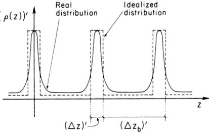
Assume that p(z)contains several Fourier com-ponents that combine to produce a density distribu-tion shown by the solid line in Fig. 1.To simplify discussion, we idealize this type of density distribu-tion by a step funcdistribu-tion-like distribudistribu-tion, shown by the dashed line. For the idealized distribution, the electron beam would have a bunch structure as shown in Fig. 2. The rectangular slabs shown in the figure are uniformly filled with electrons; the space between slabs is empty.
In the instantaneous rest frame of the beam, the slabs are at rest, although the electrons inside them oscillate and thus emit radiation. The radiation may consist of several Fourier components. Let us concentrate our attention on one ofthese, that which has wavelength(A)'.(The prime outside the paren-theses means that the quantity is measured in the instantaneous restframe of the beam.) If the thick-ness of each slab,(&)',satisfies(&)'~(X)'
18,
then for radiation of wavelength (A)' impinging on it, each slab will radiate essentially as a plane mirror of width(~x)'and height(~y)',i.e., as a rectangular slit with these same dimensions.2Most of the radia-tion will be contained within the first interference maximum; its horizontal and vertical angular-half widths near the forward direction are(2) (1)
[
Am
n = 0 p(z) dz
»
1.
As noted earlier, for a high-modulation beam the photon intensity
I(t)
as a function of time will have high-frequency Fourier components. WhenX
m:s
10-4 cm,
w
~ 1.9 · 1015sec-I.To simplify discussion, we will assume for the moment thatp(z)contains only one Fourier compo-nent with wavelengthAm,i.e.,am'
==
Om',m.(The more general case is a straightforward extension of this simple one. ) We also assume that the numbern
of electrons located within az
interval of length Amis The density of ideal circulating electrons as a function ofz
(the position along the design orbit) can be written as a sum of Fourier componentswhereLois the circumference of the design orbit, and
am
=a*-m'
becausep(z) is real.For densities high enough to satisfy condition (2), the intensity of the electromagnetic radiation emit-ted by a high-modulation beam can be much higher than for a usual beam (Le., one with more slowly varying densit( distribution). More precisely, it can be shown that ,2for a radiation wavelengthA~ Am, the radiated intensity may be of the order ofntimes higher than for usual beams. In particular, we shall see that using an optical laser, one can set up a high-modulation electron beam in which Am is of the order 10-3to 10-6em or even shorter, and which can, therefore, radiate orders of magnitude more pho-tons in the microwave, optical and x-ray regions than usual beams would.
Actually, Eqs. (3) hold only ifthe electron density within each slab is uniformly smeared out. Real electron distributions are not like that, but Eqs. (3) are still approximately valid, provided that the electron distribution is approximately uniform and that there is at least one electron for each[(Am)'/4]2 area of the(x,y)surface of each slab, i.e., provided that the number of electrons in a slab-shaped bunch satisfies
N ~ (dx)' · (dy)'I(X~)'. (4)
Viewed from the laboratory frame, the angles are Lorentz contracted, so that (unprimed quantities refer to the laboratory frame) with y
=
(1 -v
2Ic
2( p (
Z ) )' Real Idealized distribution /distribution r , r I I I I I I I I : I I I I I I I I I I I I I : : I I I , I Iz
(~Z)/iJ
r
FIGURE 1. The electron densitypas a function ofz (the position along the design orbit) is shown by the
solid line. This distribution is approximated by the step-function-like (unrealistic) distribution curve illustrated by the dashed curve. A prime on a quantity in brackets [e.g.,(z)'] means that the quantity is measured in the beam rest frame.
I
/'
----
~---/-
I
(~x)'
---
-_.~ Zl '" / '" '" '" / 7~ ;>(/L(~Z)I
FIGURE 2. The electron density(p)'is assumed to have a step-function-like dependence on(z)'(as shown by the dashed line in Fig. 1) and also on(x)'and(v)' .Viewed from the rest frame of the electron beam, such an idealized electron beam consists of a series of slabs, each uniformly filled up with electrons, and with no electrons between the slabs. Quantities measured in the beam restframe are denoted as in Fig. 1.
X (X)' 1 In Eqs. (5), we have used the fact that for photons
Y2~Ox== ~ Y 2
-emitted near the forward direction in the beam rest
~x ~x y'
frame \ ~ (\)'/2y.
Y2~()y= - -X ~
'i1---.
(X)' 1 (5) Single electrons (or several incoherently actingtypical angle ~flOo~)'-1.Equations (5) show that as a result of the assumed beam structure, the emitted electromagnetic radiation (including syn-chrotron radiation) is confined to angles of order
AI~xandAI~ytimes less in the horizontal and ver-tical planes, respectively. Thus the brightness of the emitted radiation will increase3by a factor of~yIA,
orLlx· LlyIA2,even if the total radiation intensity is
unchanged. For example, whenAx-fly> 102
X,
in principle3one can increase brightness by a factor104 even without and beyond that which results from the increase of total intensity described in the previous section.
Furthermore, for this reason, one can increase the cross section of a high-modulation beam (and per-haps put more electrons in a bunch) without a proportional deterioration of photon focusability.
4. Modifying the Energy Spectrum
The idealized beam structure depicted in Fig.
2
resembles a crystal in that here too, the radiating electrons are confined to regularly spaced parallel surfaces. Consider again that Fourier component of the radiation which has wavelength (X)' and is emitted at an angle(Ox)', (Oy)' (measured in the beam
restframe). If (Llz)' «(A)', then each electron bunch of length (~z)',can be considered to be ap-proximately a single plane. One can then use the Bragg conditions to calculate which frequencies will be suppressed and which will be enhanced for any given
Ox
andOr.
Since the planes are far from infinite in extension· along x and y, higher interference orders have to be considered. The phenomenon becomes particularly simple4when(Ax)',(fly)'«(X)' .
Experiments where the above characteristics would be important include the following:
High-accuracy (decay) time measurements, by means of phase-shift observation on a Fourier component of I(t). A.P. Sabersky and I.H. Munr05 were the first to perform such measurements on a storage ring. Anexperiment is now in progressO at SPEAR where the F ourler component used is the thirty-fifth harmonic of the revolution frequency to achieve 3-psec time resolution. In this kind of experiment, the accuracy generally increases as the frequency of the used Fourier component increases. For high-modulation beams, one could havew ~
2-lOIS sec-I.
X-ray holography. Pumping x-ray lasers with synchrotron radiation.
Both of the above require high instantaneous brightness, which could be provided by high-modu-lation beams.
X-ray lasers can themselves be utilized to "boot-strap" the beam modulation wavelength to lower values. This will be explained below.
Free-electron lasers. When high-modulation beams are sent into the laser, the lasing threshold can be lowered, and the power output increased. The energy separator described in the next section makes it possible to raise the power output beyond what is considered at present to be its theoretical upper limit.7The method of compensation also de-scribed, further improves performance.
Inall such experiments it is the high modulation of the beam which yields the high radiation inten-sity, whatever may be the nature of forces which ac-celerate the electron bunches at the moment of photon emission. Those forces can be magneto static (as in a bending magnet or static wiggler) elec-tromagnetic (e.g. a travelling wave in an undulator or free electron laser), etc.
The desirable features of high modulation beams (intensity, brightness, spectrum, time structure) and the variety of experiments which could utilize them suggest that in future storage rings intended wholly or partly for photon generation, the option to pro-duce high modulation beams should be available. The devices (to be described below) which can pro-duce such beams should be kept in mind in the design work, and, at the least, space should be pro-vided where they can be installed.
III. PRODUCTION OF HIGH-MODULATION BEAMS
We describe a method in which high beam modula-tion is achieved in four steps.g
First, the angular spread ofthe beam is decreased. Second, a strong correlation is induced between the circulating electron energy and one of the transverse coordinates (say x) by a device referred to as the "" energy separator." Third, the electron energies are altered by the "energy modulator"; and finally, fourth, beam-density modulation is produced in the "beam buncher."
We begin by describing the last two steps, and then return to the first two.
x
z
a (z')Bk3~
..
®
~.,'-'
- t - - - _ _ .-r
\3~'-ZI
\ 1. 3~1 \ \ Z=Ae
\
\ E
\E
\ \ \ \ \ 10\ \\ \01 \ \-8
\ \
\ \ \ \ \ \'" \ ~E \
'\-FaFE \...
\.... \.... \ . \ .... \ F x=A
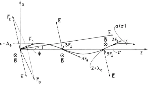
e...~ :....~... _..._-FIGURE 3. In the energy modulator, the electrons travel along a path resembling a sine wave (solid line). The curve is periodic with a wavelength Ae,its amplitudeisAe•The slope of the path atZistga (z), a (z), ais shown for one particularZ==z'value.Aplane electromagnetic wave of wavelength Atravels parallel to the [x, z]plane (A can be
<<
Aeand is not shown). The momentum k of the wave makes an angleljJwith thezaxis. The electric and magnetic fields associated with the wave, E and B respectively, are illustrated for three zvalues. The electric and magnetic force exerted on an electron at some pointzby the wave, FE(Z)and FB(Z) respectively, is shown at one point. The total electromagnetic force F ==FE
+
FBhas componentFIandF-1-parallel and perpendicular to the electron path. For better visibility, 3F
11and3F-1-(rather than FilanclF-1-)are
shown for three values ofz.
(6a) (6b) In certain cases some of the following four
addi-tional steps may also be desirable: refocusing, de-focusing, beam debunching, beam demodulation. These four steps will be discussed last.
Energy Modulator. Assume for the time being thatall electrons move along the design orbit, i.e., their energy and momentum spreads are zero. We will later consider the effect of finite dEand ~.
In the energy modulator, the electrons move along a sinusoidal path. During their motion they interact with a plane electromagnetic wave. The mechanism that modulates the electron energy is essentially that which is employed for microwave generation in undulators9(see Fig. 3). Note that in the device to be described here, the axis of the curve along which the electrons move (the
z
axis) may not be parallel to the line along which the electromagnetic wave propa-gates.Let the electrons move along a curve which resembles a sine wave of wavelengthAi' and ampli-tudeAe(see Fig. 3). The amplitudeAedepends on
the electron energyEe ,while
A
eis independent ofEeto a very good approximation. In practice it is easier
to achieve electron paths that are not sinusoidal, but for which every period of the curve is formed by a sequence of two smoothly joined circular arcs. The deviation of such a path from a true sine curve will be of the order(Ae
/A
e)3, small whenAe«
A
e •Curves consisting of a sequence of circular arcs can be realized by letting the electrons traverse a section-wise-constant magnetic field in which the field has equal magnitude in all sections but switches sign at each boundary between sections. In the following we assume that the electrons follow a sinusoidal path to an adequate approximation.The electron path lies in the(x,z )plane~thezaxis is parallel to the axis of the sine curve. The x and z coordinates of the electron are given at any timetby
2rr
x(t)
=
Ae sinT
z(t), ez(t)== Zo
+
Vz(t - to)Let V x and Vz be the x and z components of the electron velocityVe ,and
v
zthe average (over t) ofvz•The electron velocity makes an angle a with the z
aM
==
2rrAe/A
e• (7)When 2rrAe
«
A
e , one can write Iv Ix<
~ (2rrA /e Ae)Ve, so thatFEy
=
0, FRy=
0The total electromagnetic force exerted on the electron by the wave is
F
=
FE+
FB •The longitudinal component (i. e., the component parallel to the instantaneous electron velocity) is
Ve
FII=F ~
=
v
Ee{[cosf/J - ~ cos al sin a
+
[-sint/J
+
C ,
Vz ~ Ve
+
0
[(2rrAe/A
e)2], (8)and Vz
==
Veup to second order in aM.The electrons interact with an electromagnetic plane wave of wavelength
A.
The plane wave travels in vacuum (except for the electrons with which it interacts); thus its angular frequency isw= 2rrc/A. The momentum of the plane wave is parallel to the(x,z)plane and makes an anglet/Jwith the z axis (see Fig. 3). The electric field associated with the wave points along an axis that is obtained by rotating thex axis byf/Jaround z X x. The value ofthe electric field at point x, y at time I is (independent ofy)
{ 2rr
E = Eoeos wI - - - [z(t) cos
t/J
A
+
x(t)sin
l/J]
+
et>o}.
(9)The electric and magnetic force exerted by the electromagnetic wave on the electron areFEand FB
respectively. Their components are
FEx
=
Eecost/J,
FBx==
Ve Ee cosa,
F
II ~ Eoe -- - - - -Ve 2rrAe CA
e 2{[cos(~:
z-et»]
( 2rr
x
sin
l/J)
cos-X+
[cos
(~:
z
+
et» ] cos-X( 2rr
x
sin
l/J )
tin
(~:
z -
et>)J
sin - X( 2rr
x
sin
l/J)
+
[Sin
(~:
z
+
et> )]sin (
2;_ x
sin
l/J )
C
Ve
cos a] cos a - [-sin
t/J
while its tranvserse component along the directiony
X veis
v
eJ
+.~
sin
a]sin
a . (lOb)Substitution ofEqs. (6) and (9) in Eqs. (10) gives
F11andF1-as a function of time. Fortunately, for our purposes it is not necessary to deal with the full complexity of these equations. First, the velocity changes in the energy modulator turn out to be negligible, so that we can considerVea constant,Ve~
c.
Furthermore, we will consider cases whena«
1 andt/J
«
1, which allows us to approximate the trigonometric functions by their power series expan-sion in a andt/J
(except when in the argument of another trigonometric function). In this manner, we may write to a sufficient approximation£11
=
Ee a/2 [a2V; -
l/J2
+
2 (1 -
~)
]
+
(l -(/12)(a
~
-
l/J) } ,
F~
=Ee {
(l -(ih)y2 [a
2V;_l/J2
+
2 (1- V; )]
-
a(a
~
-
l/J ) }
Since F
11 is proportional to the first power of the
small quantities
a
andt/J,
whileF1-is at least second order in them, we neglectF1in the following. InF11we keep only terms proportional to the first power in
a
andt/J
then substitute fora
andE:V e
I
F~=
F - FII-I;-e-
I = Ee
[cosl/J
(6d) ( 6c) ( lOa) z(t). Cc
Ve Ee sina,
dx dz 2rr cos Vesinalcos a},
C
a = arctg
FEz
=
-Eesint/J,
2rrAe
A
e- Eel/t
I
(COS cjJ) COS(J.{
Xsin l/t )
+
(sin
cjJ)sin
C
3
x
7T xsin l/t)
I,
(IIa)
where
The main contribution to
a
Eeis due to the first term in the first curly bracket in Eq. (11 a). The rest of the terms oscillate as a function ofz,
their integral over a large enoughL will be relatively small; we neglect these "small terms".With
v
e ~c
and Eqs. (7) and (12),When
cP
==
wI-2rr
A
z
cos I/J+
cPo.
(lIb)aEe
~eE
oaM/2 (cos ¢o)L ( 1- s)
( 16a)~
=~
(~
- cosI/J),
(
13 )A
eA
vzf
ZO+LaEe
= dz FII(z) zo 2 Af
zO+L rr e V e= Eoe - \ - - ~(cos ¢o) dz
Ae C zo
(16b)
f
zO+L 2rrX dz sin2
-zo
A
Clearly, if conditions (12) and (13) are satisfied, an electron passing through the energy modulator will gain an amount of energy that is approximately proportional toL.The energy gain may be positive (if -rr/2
<
¢o<
rr/2) or negative (if rr/2<
¢o<
3rr/2) or zero (if ¢o=±
rr/2). If forsomez
o the cos¢o = 1, then forZo
+
A/2 one has cos ¢o=
-1.Electrons located in one A/2 long section of the beam will increase their energy as a result ofpassing through the energy modulator, while electrons in the next region of the same length will decrease their energy during passage through the device. If the wavelength
A
lies in the optical region, then energy gain and loss can thus be induced within an optical wavelength.I0In the energy modulator as just described, all electrons move along a sinusoidal path. One could instead let the electrons travel along helical paths; the formulae valid for that case are similar to the ones just given.
Beam Buucher. The purpose of this device is to transform the energy modulation into beam-density variation. The path followed by an electron is deliberately arranged to be a sensitive function of the electron energyEe•The shape ofthe paths can be chosen to suit the range of parameters with which one has to work. Here we shall discuss one of the simplest possibilities.
The electron trajectory in the beam buncher is shown by a solid line in Fig. 4. (The arcs indicated by dash-dot lines and the angle({JIwill be discussed later.) The beam buncher has total lengthD and is ( I2a) sinl/J«I, z)
+
small terms. ( 15) 2rrA
a=
A
we can write, with Eqs. (6),cos
[2;
x sin l/t]
=
1-(//2sin
2(~:-
z ) ,
( I2b)sin
[2;
XSinl/t]
""asin
~:
z.(l2c)
Provided thata is small enough, the first of these expressions will not change sign, while the second may. Provided furthermore that
from Eq. (6b) t
=
(z - zo)/vz+
to, andcos
[~:
z -
cjJJ =cos
cf>o
(14a)z
2rrcf>o= -w (to-;z) -cjJo
""-X
(zo-cto)-cjJo.( I4b) Clearly, if Eq. (13) holds, COS[(21T/Ae)Z - <1>] does not depend on
z.
When Eqs. (12) and (13) are satis-fied, the energy gained by an electron passing through the energy modulator will bedivided into three sections. The first and third are
D/4
long, while the second has lengthD/2.
The electron enters atz== 0 with velocity parallel to the z axis. Its trajectory is a sequence of three smoothly joined circular arcs. The length of the trajectory in the first, second and third sections has lengths respectively8/4,8/2
and8/4.
We have from Fig.4,
~8 =
RqJ
and ~D=
RsinqJ,
so thatExpanding
qJ
= arc sin(D/4R)
in powers ofu
=D/R,
one obtains8
= D+
1/ 96 Du2[1 - 2.813 · 10-
2 u2+
1.041 · 10-
3 u4+
0(u6)]. (18)
The radiusR is proportionaltoEe- WhenEechanges by an amount
oEe
«
Ee' then R
changes byoR
«
R, and 8 changes by an amount
1 {
oR
08=-·
Du2 -2 -
+
3
96 R+
0[(
~)
3] }
flu) feu) =[1 - 5.626· 10-
2 u2+
0(u4 )] (19)Thus, if two electrons enter the beam buncher at the same time, but one has energyEe,while the other has
Ee
+
oEe,
the former electron will leave the device first, and at that moment will be be ahead ofthe latter electron byoS.
~""" .'~
...
B
o
I 1r
---
J I ....1···. I ':1 ... I .f 1ep /...
I .... I~ .... IR
/::-icp I : .... I I I I I I I I I ~ 0/4-)""''''---I IB
Q9
0/2x
B
o
I I .i· .···1.... .... I',....
:
.... ~". I<p '. I I ". I . I Iz
I I I I I I I 1 I I I I I I I I I : --~J....::...-.-0/4~ I IFIGURE 4. The beam buncher has total lengthD. Itconsists of three sections: the first and third have length D/4, the second D/210ng. The magnetic field B is uniform in each section, perpendicular to the plane of the drawing, and its orientation is shown for all three sections. The field intensity is the same in all sections, Anelectron travels along the solid curve.Itenters the beam buncher atz= O. There its velocity is parallel to thezaxis. Due to the presence of the magnetic fields, the electron trajectory consists of three smoothly joined circular arcs of radiusR. The length of the first and third arc isS14,that of the second isS12.
When the magnetic field in the energy modulator is unifonn, one may prefer to have the electrons enter and leave the buncher not parallel to thezaxis, but at an angleqJ 1,along the arcs drawn with dash-dot lines.
which implies
Zo
cos ¢o = sin 2rr
X ·
(21)217' 3
T
eto+
C/>O = -2
rr, (20)Fourier Transform of p. To calculate the Fourier transform,F(w),ofp(zJ)'one must knowpfor allz.r,
but to calculateF(w) forw
»
2 17'/A,
it suffices to know the behavior ofpnearzfO). Inour case, forZJ nearzJ(O) one has p~z;2/ . Therefore,If one chooses
Bootstrapping the modulation frequency. Once the beam modulation is sufficiently high to produce soft
F(w) ~ W-1/3 (25)
forw
»
2rr/X. Evidently, pis rich in high Fourier components: w can be increased by a factor of a thousand before F(w) decreases by one order of magnitude.The validity of our approximation is limited by the second term in the curly bracket in Eq. (22). In practice, a more severe limitation is presented by the accuracy with which the guiding fields can be maintained in the ring and by the finite momentum and energy spread of the circulating beam.
(23) approximated by a power series. (The other elec-trons will give a more slowly varying "background" density distribution, which is of less interest to us at the moment.) For these
D 2 oEe 27TZo
I
1
(27TZO) 2)
oS
~-
- u j ( u ) - -1 - - -
.
48 Ee
X
6
X
then in the first approximation (when the second term in the curly bracket can be neglected) Eq. (23) gives
oS
= -Zoso that as a result of traversing the buncher, all electrons will end up at the same point together with that electron which att=to
was atZo=
0,i.e., at pointZJ(0). In this approximation,Z1
Zo)=
zJ(O) for allZo0 The density will be infinite at the "catastrophic point" zJ(O). Inthe secondapprox~
mation the density is finite, but highatz10)(see Fig. 5). The result is a density distributionpwhich falls off as
zj2/3
near the pointsz/(O)+
nA,wherenis any integer. Thisp(z/)is of the type illustrated in Fig. 1 by the solid line.(22) D oEe { 27TZo
oS
= -
- u2f(u)-- s i n -48 EeX
[ (
OE
e) • 2 27TZo ] }+
0 - - sIn - - . EeX
Since in the buncherr -.., Ee,one hasoR/R
==
oEe/Ee. To simplify discussion, consider only the important case when l/J= O. Then Eqs. (16) and (19) giveThe energy change induced in the energy modu-lator is the same for electrons at positionsZ andZ
+
n
A
(wherenis any integer); the energy modulation will be periodic inZ with a periodX;
therefore thebeam-density modulation produced is also periodic by
A
inz.It is important to notice that this periodicity need not be simple harmonic. Instead, it may contain a significant admixture of much shorter wavelength Fourier components
\n
«
X.
The amplitude of these components depends on the parameters of the beam buncher. WhenX
is in the optical range,\n
may be in the x-ray region.We now study the density function produced by that particular beam buncher for which Eq. (19) holds. Since the density is periodic, it suffices to investigate those electrons which at time to (before traversing the buncher) are located in the interval
- Y2
A<
Z :::;Y2
A. Without loss of generality one may choose the reference point in time so thatTypically,oEe/Ee~ 10-5for a high-energy stor-age ring. Therefore, for most purposes the second term in the curly bracket can be neglected. In this approximation,
oS
goes to zero as Zo does: an electron located at Zo = 0 when t = towill travel a distance S while traversing the buncher to a point which we denote byZ j (0). Electrons with slightlylarger Zo values will have a negative oS: after traversing the buncher, they will be displaced to-wardszJ(O) and end up at pointZj(zo),
Let us concentrate our attention on electrons with sufficiently small Zo, so that sin 27TZo
/X
can beCPo
8S
/j---j'----: / /----_.. _---/ [ ] (1)Zf(ZO)-Zf(O)
C
[Zt (ZO)- Zt(
0)]
..._--_...
_._---;~</
---,t/---
eo_A_/! :FIGURE 5. The quantity[z /(zo)-zjO)]is shown as a function ofzooIs is assumed thattois chosen so that cos ¢o= cos2rrzo/X,and the solid curve shows ¢o as a functionofzo.In part of the figure it is also assumed that Eq. (24) holds, so that 8S= -cos¢o. The 8S is indicated for one particularZovalue:
zb.
To find the quantity[z /(zo)-z/(0)] for anyzo,draw lines as shown by the arrows: first a vertical linefromzoto the solid curve, then from there a horizontal line to the dash-dot curve. The distance between the dash-dot curve and the vertical axis is[z /(zo)-z/(O)].For smallzo/X,the approximation to Eq. (23) is shown by the dotted horizontal arrows:[Zf(Zo)-~f(O)]==O.When the left hand side of Eq. (24)
>
1, the dot curve is to be replaced by a curve like the dash-double-dot line.x-rays in large enough quantities for pumping a soft x-ray laserll(e.g., Li II or Li III laser), one may use the collimated coherent radiation generated by this laser as the electromagnetic wave in a second energy modulator. The procedure described earlier can now be repeated with this wave, so that in principle one can induce a fundamental harmonic in the electron density which lies in the soft x-ray region as well as higher harmonics of even shorter wave-length. These harmonics will then enhance the intensity of x-rays emitted by the beam in this shorter wavelength region. Those x-rays may in turn be used to pump a shorter wavelength x-ray laser, etc.
Practical realization of this sequence of "boot-strapping" steps will be more difficult as higher
modulation frequencies are reached. Partly because to pump a shorter wavelength x-ray laser one needs higher instantaneous pumping photon brightness, partly because the tolerances on guiding fields in the energy modulator, beam buncher, etc., are then smaller, and partly, because higher electron density is required ifn is to be the same for smaller Am.
Finite Momentum and Energy Spread. To simplify our discussion, we assume that the vertical momen-tum spread~py ~ p~y'is negligible (otherwise~py
can be treated" as dpxwill be).
The horizontal momentum spread dpx can be neglected, provided that it is smaller than some criticalilpo
Subsequently the electrons are focused to form an essentially parallel beam. At any pointx,the beam will contain electrons with energy lying within an interval of total width
since
e -....
R-l-....£;1. If the electrons are now
al-lowed to travel a distanceHin a force-free vacuun to point
zc,
the distance J1xbetween these two .elec-trons perpendicular to the momentum of the Ideal electron will be~Px
<
~PO==
pJ1x1J. (26)(the value ofJ1xlJwill be evaluated later). In such a case, the discussion of the preceding sections is valid. When~Pxviolates condition (26), our aim is to change the electron phase-space distribution so the inequality (26) should hold.
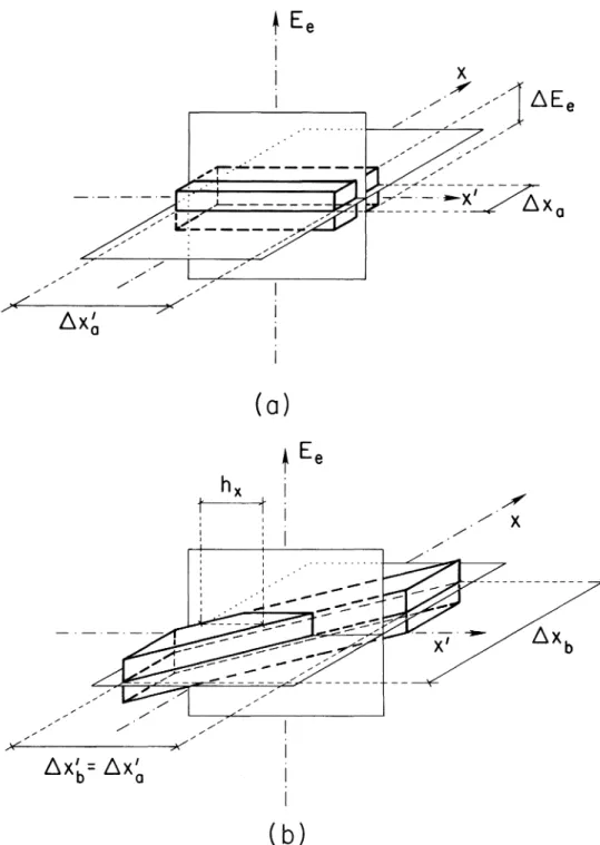
Changes in the electron phase-space volume are illustrated in Figs. 6 a-f. In these figures three-dimensional projections of the (six-three-dimensional) electron phase-space volume are shown. For ease of illustration, a step-function-like (unrealistic) phase-space distribution is assumed. With this unrealistic distribution the(x,x) phase space ellipse is ideali-zed as a "phase-space quadrangle", as can be observed by looking at the projection of the
distri-butions onto the(x,x') plane. (29)
Spreading the Beam. It is assumed that originally (at pointZaalong the orbit) the total horizontal
an-gular spreadJ1~violates condition (26). The pointZa
is so chosen that here the horizontal phase-space quadrangle is "upright", Le., its neighboring sides are orthogonal to each other (Fig. 6a).
To reduce~x',the beam is first allowed to spread along thexaxis. This increases..ix,but leavesJ1~as well as the total phase-spacevolti~meunchanged. By the time the electrons reach Zh, the phase-space volume has assumed the shape shown in Fig. 6b. Next the electrons are focused so that when they ar-rive at pointZe,the phase-space quadrangle is again
""upright", but now ..ix'== ~x:, satisfies inequality (26) (see Fig. 6c).
Since the focal length of a magnetic lens depends on the electron energy Ee , atZc some correlation
exists betweenEeandx.This correlation causes an
additional momentum spread8px along thex axis. Denoting by Eeo the nominal electron energy, one
can show that( in the thin-lens approximation)8px
<
2pl..l.~I..lEefEl" We neglect 8pxin what follows. Energy Separator. Its purpose is to induce a strong correlation betweenEeand x. In principle it can be asimple device. For example:
Let an electron travel a distance I in a homo-geneous magnetic field. As aresult~the electron will change its direction bv (..) ~ IIR. For an electron
whos~energy is the noti'1inal energyEeo •one has (..)==
(")(E('o). while for electrons with some other energy El,
==
Ed)+
~/2 ~El" the angle isThe resulting phase-space volume is illustrated in Fig. 6d. At this stage~Pxis negligible and~FEt'
«
Me.
Next the electrons traverse the energy modu-lator, where their energy is altered by8EI?' as given in Eq. (16). This alteration will not be washed out by the background energy spread, provided thatY2Er,e~!'vlL ~ Y2 ~FEt'. (30)
Note that if the energy separator is omitted, Le., if the step illustrated in Fig. 6d is absent, then it would still be possible to induce in the beam the desired density variation, but only if one satisfied the condition
( 30a) For given Q!AfL,the energy separator thus allows a reduction in Eo by a factor
Mel
~FEe' Since the power of an electromagnetic wave is proportional toE(~, this will lead to a large reduction of the (e.g., laser) power requirements when ~FElj~Ee
«
1.TheQ!.\/decreases with Eeif the magnetic field in
the energy modulator is fixed. Therefore,8Eewill be smaller for higher-energy electrons. One may have to compensate for this. A magnetic field will accom-plish such a compensation if its gradient alongxhas the appropriate (positive) value (see Fig. 6d).
In an alternative approach, the magnetic field in the energy modulator may be uniform, and compen-sation is achieved by making the electrons enter the beam buncher at an angle([JI (dash-dot line in Fig. 4)
instead of entering along the axis (solid line in Fig. 4). In this manner, choosing({J\
<
0, one can insurethat for electrons with larger x (and thus El. ) the
~
E
e
I
I
I .', J -, /,,".
:" .,."'/ , / ~-- - - ---;.,.'" . , . , / , / " , , , , " " ' " " " - - -_ _- - - , ...,.r ,./ ,,/l:::,.x
Ia
(0)
t
E
e
h
xI
I I .,.-.,.-/ ,)«\("'---'---:;);.:.; .,.l:::,.x'
b
=
l:::,.x'
a
( b)
/
.,./
X
FIGURE 6. Projections of the (six dimensional) electron phase space are shown. Step-function-like (unrealistic) distributions are assumed to simplify illustration.
a. Three-dimensional projection of the electron phase space at somepointzualong the orbit. The fuJI beam width alongx is~xQ'the total angular spread in the horizontal plane is~x'Qand the full spread in the circulating energyEe'is~Ee'The~\'Q is assumed to be larger than the critical ~x'0'
b. By the time the electrons reach pointZ/Jalong their trajectory. the beam width alongxhas increased to
tub' Now for any value ofxthe total angular spread is~h.\.
<
tuo,but the total angular spread in the horizontal plane is still~x'b= ~x'Q'~~:..----,t'-_.-._._._.~ X'
",' / ,,/
~===~ ----l ,," / " '" ",,// . ,"(c)
/ / X / , /~---(d)
c. At pointZc the angular spread is reduced fromdx'b todx'c= h.,.,while8Xc= dxbis unchanged. The far and near ends ofthe illustrated phase-space projection are vertical quadrangles (parallel to the[x'.Ee] plane). Neighboring sides of these quadrangles are not perpendicular, because electrons with higher than average circulating energy are focused less. After this point, the electrons enter the energy separator. d. The energy separator induces a correlation between the circulating electron energyEeandx.The total width of the beam is further increased to8Xd
>
dxc.The figure shows the phase space at pointzc'just after the electrons leave the energy separator. To make illustration easier, the phase-space volume is assumed to consist ofthree disconnected pieces. Dashed line means that it is below the[x', xlplane, or behind the[x',Ee] plane, or both. (In reality the phase-space volume is continuous.) Each piece has an energy spread~FEe<
Me.The result is that at any chosen value ofxthe energy spread is less than in Fig. a, b, or c. The ratio flEe/8FEecan be large, ifdxd/dxcis. After this stage the electrons enter the energy modulator.
#' ./ X ~---.,I.-:_.
_. _.
~z
( e )
t~
I / I ./' I ./' X I . /, / ./' _ . - . _ . - .~
Z I . / ./' I . / ./' I . / I( f )
e. The energy modulator changes the energy of the electrons. The energy change is a function of thez coordinate. (Note the change of axis.)
f. Electrons enter the beam buncher. Those with higher energy will fall behind, while those with lower energy get ahead of electrons of average energy. The result is a beam-density modulation of optical and suboptical dimensions.
amount
Ee-Eff)
0<PI
==
<PIR - - = (const) xEeo (31)
L
[cos (I/; ± ~ ~.x6)]-1 -L
(cos 1/;)-1 ~N4.
(33a) The phase of the electromagnetic wave in the energy
modulator contains a term 2rrsinl/;, and since by assumptionEe~x (see Fig. 6d), all electrons with the same ¢o will have the same
z
coordinate (moduloX) after the buncher, if the constant onth~ right-hand side of Eq. (31) satisfies- 2 rr sin I/;= const.
Refocusing.For certain applications, one more step is needed: the beam has to be refocused and its cross section reduced in order to achieve high electron density while the beam radiates the photons of interest in the region of space of interest (e.g., synchrotron-radiation photons while passing in front of the exit port; coherent photons between the mirrors of a free-electron laser, etc.). The~Pxcan be large here, subject only to the condition that high electron density and its modulation should persist throughout the region of interest.
To insure that refocusing will not wash out a density modulation with wavelength
Aw,
all elec-trons have to arrive at the focal plane with a time accuracy of±Aw/8c.
In principle this can always be done; an electron located at point (xi,z) before refocusing will travel a distancel~f+
~xl/ fto thefocal point,
iff»
x
is the focal length. All electrons which have the samez
coordinate before refocusing, and for which!XiIs
~ ~will reach the focus with the required time accuracy, provided that(32) In practice, as in the example to be given below, one may prefer to induce in the beam a correlation betweenEe andy (instead ofx). To illustrate this case, one should replacex byy in Figs. 6d and 6e. Proper timing is then insured by the inequality obtained from (32) by replacing in it~xby~y.Since usually ~y
<<
~x, for this case smallerf
will suffice.Determination of
dxO
To lowest order, conditions on ~x0 can be
obtained as follows. Electrons entering the energy modulator at an angle~~'0\\rill gradually get out of phase with the electromagnetic wave unless
Furthermore, the electrons will deviate byLx'0from
the design orbit at the far end of the energy modu-lator, which will wash out the correlationbetweenEe andx, unless
(33b) Similar (lowest-order) considerations for the beam buncher and for the process ofrefocusing (ifneeded) lead to the additional conditions
where~Jis the total horizontal beam diameter to be achieved after refocusing.
Compensation: Defocusing, beam debunching, energy demodulation. The length of an electron trajectory around the storage ring may vary by more than A
from one turn around the ring to the next, or, at any rate, after a few turns around the ring.Anelectron which gained energy during one traversal through the energy modulator may either gain or lose energy during the next traversal, or anyone of the following traversals. Therefore the average energ)' gained by an electron will increase with time ast1/2•To avoid
blowing up the beam, the average energy gained by an electron during one traversal of the energy modu-lator must not exceed the average energy radiated away by the electron during one trip around the ring. This condition limits DEe.
That limitation can be circumvented as follows. After the bunched beam emits the desired photons, we immediately undo what we did to the beam to bunch it. As an illustration, imagine that one takes a motion picture of the electrons as they change their energies while moving through the beam buncher, and eventually the emergence of electron bunches after traversing the beam buncher. Running this motion picture backwards, it would show the disap-pearance of bunches as the electrons move back-wards through the beam buncher, and finally, all
TABLE I
The first part of the table gives the beam characteristics of the storage ring. The values are similar to those calculated for SPEAR in single-beam mode operation, when the horizontal-vertical coupling isK= 0.1, and when the magnets are tuned for this operating mode. The circulating electron energy isEe'andMelEeis the full width of the gaussian energy spread,ExandEythe horizontal and vertical emittance,2ao
=
Llzthe fullgaussian bunch length.
The second part of the table refers to the energy separator, Le., the device which takes the beam phase space from a configuration illustrated in Fig. 6c, to one similar to what is shown in Fig. 6d. Before entering the energy separator, the beam has horizontal (r.m.s.) diameterLlxeandtotal horizontal (r.m.s.) angular spread Llx;.After leaving the energy separator, the corresponding values areLlxdandxd.TheLlYe, Lly;, LlYdand LlYd are defined similarly. Note that whereas in Fig. 6d the energy is correlated with thexcoordinate(LlXd
>
dxc),here we assume that the energy separatorcorrelatesEewith theYcoordinate, therefore nowL\.yd>
L\.yc'The ratioL\.Yd/L\.Yc~flEe/ L\.FEe= 25.
The third part of the table describes the parameters of the energy modulator, Le., the device in which (see Fig. 3) an electromagnetic wave of wavelengthA and (electric) amplitudeEo modulates the energy of
electrons moving along an approximately sinusoidal path of wavelengthAeand amplitudeAe'The maximum
angle which the electron path makes with thezaxis isCiMand the maximum energy transferred to the
electrons isfJEM.The electromagnetic wave travels along a line whose direction makes an anglel/Jwith thez
axis. The static magnetic field in the modulator isBS
•Choose thel/J
=
0andB~=
O. To insure that the energyspread of the electrons will not wash out the effect of the energy modulator, the static field gradients
a
J3~,anda
zB~are non-zero. At the center of the modulator the magnetic field has componentsBovandBoz' RIS
the average radius of curvature of the electron trajectory in the modulator. The beam dimensions in the modulator are as in the energy separator:~xd'L\.yd(listed in the first part of the table).The electromagnetic field is assumed to be produced by a laser, synchronized with the circulating electron bunch. The laser pulse is assumed to fill a cylinder with horizontal and vertical diameters2dxd, 2L\.yd'and 2.5 Llz long.
The fourth part refers to the beam buncher. The beam dimensions are approximately as in the energy modulator:~d'L\.yd'The magnetic field isBb'The radius ofcurvature for an electron with circulating energy 2.5 GeV isRb .The length (alongz)of the buncher isD.Mter traversing the buncher, the difference between
thez coordinate of an electron which gained
I
oE
eMI
energy in the modulator, and one which lostI
oE
eMI
energy in the modulator, will decrease byoS.To insure effective bunching withAm= A,one needs
oS
= A12 (satisfied here). Beam Characteristics Energy Separator Energy Modulator E eO' 2.5 GeV lhL\.Ee/Ee 0.5' 10-3 Ex 10-1mm'm rad Ey 10-3mm'm rad Uz 1 cm L\.xc= L\.xd 4mm L\.xc'= L\.x/ 0.1 m rad L\.Yc 0.1 mmL\.yc'=L\.Yd' 10-2m rad
L\.Yd 2.5 mm L\.FEe 50 keY A 10-4em Eo 1.22· 105V/em Ae 12 cm A e 6.12' 10-3em QM 4.08' 10-3 DEe 50 keY t/J 0 L\.z 2 em
Beam Buneher B~O B~o ByB.~ BzB: R L\z
Energy in one laser pulse Instantaneous laser power Average laser power Average laser power with 200
reflections Bb Rb D u2= D2/R2 L\S 10.2 kG
o
2.04 kG -2.04 kG/em 7.35.102em 5 em 6.26.10-4J 3.76.106W 800W 8.00W 21.4 kG 3.51· 102em 1.94.102em 0.308 5.10-5emelectrons regaining their original energy, as a result of their traversing backwards through the energy modulator. Since electromagnetic interactions are time-reversal invariant, and the beam consists of a periodic series ofmicrobunches, the same result can be obtained (except for the first and last micro-bunch) by running the electrons not backwards, but allowing them to move forward, pass through a "beam debuncher" essentially identical in construc-tion to the beam buncher, and subsequently traverse an "energy demodulator" whose construction is essentially identical to that of the beam buncher.
On the basis of the above argument it is clear that the effects of energy modulation and beam bunching can be compensated in the following manner.
If the beam was refocused after bunching, allow it to continue undisturbed until it unfocuses itself to the same size as it had immediately after the buncher. (If before focusing
E
increased withy(or x), now E may decrease with y (or x). This difference is inessential, it could be eliminated by one more focusing and subsequent defocusing. If the beam was not refocused after photon emission, it may be led directly into the debuncher. In either case, the beam entering the debuncher should be of the same size as immediately after the buncher. The beam debuncher is a device identical in construction to the beam buncher, except that in it the magnetic-field direction may be reversed It is followed by the energy demodulator, which is identical incon-struction to the energy modulator, except that in it too some electric or magnetic fields may be re-versed. At any rate, they are so arranged that if an electron gained energy
aEe
in the energy modulator, it will lose energyaEe
in the energy demodulator.Compensation will not be perfect, first, because during emission of the desired photons (at a syn-chrotron-radiation port, in an undulator or free-electron laser, etc.) free-electrons undergo random energy changes which will not be compensated. The second, more important reason is that the guiding fields in the storage ring are not perfect N everthe-less, compensation will be effective because typic-ally it is to take place within a few meters ofthe beam buncher. Therefore, electron positions have to be maintained with an accuracy about X/2 only while the particles are traveling this distance.
Since these devices are essentially identical to those discussed earlier, the conditions imposed by them on~'0can be calculated as explained above.
An Example. We assume that a storage ring like SPEAR is used in single-beam mode, with a hori-zontal-vertical coupling ofK
=
0.1, and that themagnets are tuned for such an operating mode. The first part of Table III lists the beam character-istics. The values are similar to those calculated for SPEAR in such a mode of operation The second, third and fourth parts give the parameters relevant to
the ener~y separator, energy modulator and beam buncher respectively.
It is assumed that the electromagnetic radiation is produced by a laser. In the first approximation there is no net energy transfer from the laser pulse to the electrons, since some electrons will gain energy from it while others give up their energy to enhance the pulse. The same laser pulse can, therefore, be reused. Assuming that we reflect the laser pulse 200 times and thus reuse it 100 times, the average output of the laser can be reduced by a factor of 100. Actually, so large a reduction is not crucial, since the average power output is in any case quite modest. On the other hand, re-passing the same laser pulse in the energy modulator also reduces the necessary laser repetition rate, and that is desirable for simple operation.
Ifwe had not used the energy separator, then the desired beam modulation could still have been achieved, but only with a laser with about250 times higher power output than the one needed in con-junction with the energy separator.12
ACKNOWLEDGEMENTS
While writing this, I greatly benefited from discus-sions with K.M. Monahan, P.L. Morton, A.P. Sabersky, P.B. Wilson, and H. Winick.
1. Paul L. Csonka,Particle Accelerators 8,225 (1978); Univer-sity of Oregon,I.T.S. preprint No. N.T.059/75 (1975);and Some Coherence Phenomena with Wigglers and Their Ap-plications in Wiggler Magnets, Ed. H. Winick and
T. Knight, SSRP Report No. 77/05,May, 1977. 2. This was already noted in: Paul L. Csonka,Particle
Acceler-ators 7, 9, (1975)and University of Oregon preprint N.T. 052/74 (1974).
3. For closed circular electron orbits, the reduction in hori-zontal angular spread would be washed out by the curvature of the orbit. On the other hand, it will be visible when the radiation is produced by a wiggler in which the elec.,gon trajectory deviates from thez axis by an angle~ ~()w'""~
~()x·
4. Paul L. Csonka,Particle Accelerators 7,255 (1976).For the effect of mutual Coulomb repulsion, see L.A. Rivlin,JETP Letters 13,257 (1971).
5. AP. Sabersky andIH Munro, inPicosecondPhenomen~ Ed C. V. Schenk, E P. Ippen, and S.L Shapif(~ Springer Verlag Series in ChemicalPhysic~Vol 4(1978). 6. K M Monahan, I H Munro, and V. Rehn, in preparation
7. N.A. Vinokurov, A.N. Skrinski, Institute of Nuclear Phys-ics Preprint, USSR Academy of Sciences, June,1977. 8. A simpler but less energy-efficient version of this method
was given in the first of references (1), and in Enhancement of Synchrotron Radiation by Beam Modulation, University of Oregon IT~ preprintNo NT. 059/75 (1975). The method presently described requires considerably less laser power and allows an increase of radiated output in free electron lasers.
9. H. Motz, J. Appl. Phys. 22,527 (1951);R.M. Phillips, IRE
Trans. Electron Devices231 (1960).
10. WhenrJ;=0, these expressions reduce to the corresponding ones given in Ref8.
11. Paul L. Csonka,Phys. Rev. A13,405 (1976),and Opportuni-ties to Produce Coherent Soft X-Rays at Stanford, SSRP Report77/03 (1977).
12. Without the energy separator, the energy spread ofthe beam would be~e=1.25MeV for allx. In this case8Ee
>
~~e=1.25MeV would beneeded(insteadof8Ee~~~FEe=50
keV). SinceoEe is proportional to Eo, the laser output is
proportional to(~e/~FEe)2= 625. This is partly com-pensated by the fact that the electron beam fills a smaller volume when the energy separator is not used. But this decrease is only partly effective because the smallest volume which is filled by the laser pulse is not the beam volume: it is limited from below by diffraction and multiple reflections.A product of all these factors gives about250.
![FIGURE 5. The quantity [z /(zo)-zjO)] is shown as a function of zoo Is is assumed that to is chosen so that cos ¢o = cos2rrzo/X, and the solid curve shows ¢o as a function ofzo](https://thumb-us.123doks.com/thumbv2/123dok_us/8662995.2341000/10.816.142.694.95.502/figure-quantity-shown-function-assumed-chosen-solid-function.webp)