The Global Expert in
Solid State Relay
Technology
DC Series
www.crydom.com
ABOUT US
Crydom, a brand of Custom Sensors & Technologies (CST) and
global
expert in Solid State Relay Technology
, has a distinguished record of
providing high quality, world class Solid State Relay and Control Products
for a variety of heating, lighting and motion control applications. Crydom
products, coupled with
unparalleled technical support, timely delivery
and competitive pricing
, provide Crydom’s clients with the innovative
products and support necessary to succeed in today’s competitive and
fast paced global markets.
Crydom’s extensive selection of standard off-the-shelf products is
constantly being updated and expanded through its continuous
improvement and aggressive new product development programs.
Utilizing state of the art designs, materials and technology, Crydom offers
a wide range of AC and DC output SSRs in industry standard Panel Mount,
PCB Mount and DIN Rail packages, all
meeting global safety and
standards agency requirements
such as CE, RoHS, UL, IEC, etc.
Bolstered by four decades of Solid State Relay operations experience,
Crydom also specializes and encourages
adapted and fully
custom-designed SSR products
for nearly any application where unique
specifications and optimized performance are critical for success.
Crydom’s modern purpose-built
100,000 square foot manufacturing
facility
houses all aspects of its ISO certified operation including Design
and Development Engineering, Manufacturing Operations and Quality
Assurance, Customer Service, Finance, Marketing and General
Management, permitting close coordination of all aspects of Crydom’s
activities. Applications Engineering and Sales support are both
performed in the field to provide Crydom’s Customers with the
unparalleled technical and commercial support.
Following rigid design guidelines and standards, Crydom products have
set the bench mark for SSR performance and reliability world wide. In
addition to
award winning designs
, Crydom has acquired an impressive
list of
patents
related to SSRs and Solid State Controls, while continuing
to develop new circuit and technology-related inventions as part of
extensive R&D programs
.
To learn more about Crydom SSR technology and products, or how an
alliance with Crydom can contribute to the success of your project, visit
www.crydom.com
or contact your authorized Crydom Distributor or
Crydom Customer Service Representative today.
Crydom’s new
“PowerPlus DC Series”
of DC output Panel mounted Solid
State Relays expands Crydom’s Series 1 line of DC output SSRs with new
features including an optional clear IP20 “touch safe” cover, LED input
status indicator and higher speed switching circuit minimizing switching
losses and permitting higher frequency PWM operation. The
“PowerPlus
DC
Series”
also includes new models accepting AC control voltages as well
as traditional DC control models.
The
“PowerPlus DC”
product line features Crydom’s advanced DC
switching technology utilizing low power dissipation power FETs coupled
with 2.5 Kv optical coupling which provides reliable high power DC
switching up to 100 amps and operating voltages to 400 VDC. Available
options include a 4 to 32 VDC or 90 to 140 VAC input and a factory installed
phase change thermal interface pad.
Crydom
“PowerPlus DC”
SSRs are CE certified to both the Low Voltage &
EMC Directives, RoHS & China RoHS compliant, UL and cUL Recognized.
For more information on
“PowerPlus DC”
Series SSRs, contact the
nearest Crydom Distributor, Representative or Local Crydom Sales Office,
or visit our website at www.crydom.com
“POWERPLUS DC” PANEL MOUNTED DC
OUTPUT SOLID STATE RELAYS
DC Series
Complete specifications of these & other Crydom products available at:
www.crydom.com
General Notes
(A) All parameters at 40ºC unless otherwise specified. (B) Heat sinking required, see derating curves.
(C) PWM ratings applies only for DC input models. A minimum of 8 Vdc have to be applied in the control. For more information see datasheet.
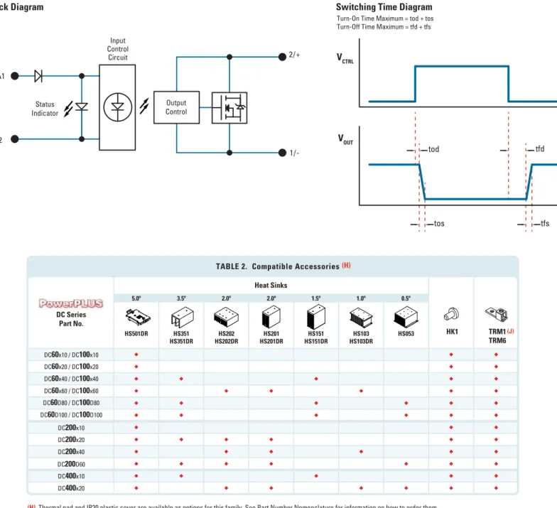
(D) See Switching Time Diagram. VOUT is typical of a resistive load.
Logic Compatible Control Inputs of either 4 to 32 VDC or 90 to 140 VAC
Optional IP20 Protective Cover & Thermal Interface Pad
Optically Isolated Trigger Circuit for enhanced switching
MOSFET Output for Low On-State Resistance
LED Input Status Indicator
UL Resistive Load ratings
CE, RoHS & China RoHS compliant
DC Series
High Current DC Output SSRs
10-100 Amp
Output Specifications
DC
200
x10
DC
200
x20
DC
200
x40
DC
200
D60
DC
400
x10
DC
400
D20
Blocking Voltage [VDC] Operating Voltage [VDC]
Maximum Off-State Leakage Current @ Rated Voltage [mA] Minimum Load Current [mA]
Maximum Surge Current (10 msec) [ADC] 71 81 167 245 32
Maximum On-State Voltage Drop @ Rated Current [VDC] 0.66 1.1 1 1.1 2.3
Thermal Resistance Junction to Case (RqJC) [°C/W] 1.05 0.85 0.51 0.42 0.57
48 3
0.45 Maximum PWM [Hz]
Nominal Output Capacitance [nf] 1
0.2 2.5 200 7-150 0.4 2.5 400 7-300 1 000 900 400 1 000 1 900 450 Output Specifications
DC
100
x10
DC
100
x20
DC
100
x40
DC
100
x60
DC
100
D80
DC
100
D100
Blocking Voltage [VDC] Operating Voltage [VDC]Maximum Off-State Leakage Current @ Rated Voltage [mA] Minimum Load Current [mA]
Maximum Surge Current (10 msec) [ADC] 66 91 136 167 215
Maximum On-State Voltage Drop @ Rated Current [VDC] 0.32 0.34 0.6 0.6 0.72
Thermal Resistance Junction to Case (RqJC) [°C/W] 1.44 0.85 0.78 0.58 0.55
272 0.56
0.42 Maximum PWM [Hz]
Nominal Output Capacitance [nf] 1
0.15 2.5 100 7-72 1 000 1 000 900 800 550 450 Output Specifications
DC
60
x10
DC
60
x20
DC
60
x40
DC
60
x60
DC
60
D80
DC
60
D100
Blocking Voltage [VDC] Operating Voltage [VDC]Maximum Off-State Leakage Current @ Rated Voltage [mA] Minimum Load Current [mA]
Maximum Surge Current (10 msec) [ADC] 78 108 163 200 258
Maximum On-State Voltage Drop @ Rated Current [VDC] 0.33 0.35 0.62 0.62 0.75
Thermal Resistance Junction to Case (RqJC) [°C/W] 2.1 1.2 1.1 0.8 0.7
326 0.59
0.53 Maximum PWM [Hz]
Nominal Output Capacitance [nf] 1
0.1 2.5 60 7-48 1 000 1 000 900 900 700 700 (A) (A) (A) (C) (C) (C) Input Specifications Control Voltage Range Minimum Turn-On Voltage Must Turn-Off Voltage Maximum Reverse Voltage Minimum Input Current (for On-State) Maximum Input Current Nominal Input Impedance
Maximum Turn-On Time (tod + tos) [µsec] Maximum Turn-Off Time (tfd + tfs) [µsec]
-32 VDC 10 050 11 mA @ 4 VDC 12 mA @ 32 VDC 320 75 4 - 32 VDC 4 VDC 1.5 VDC
Input is Current Regulated
10 080
DCxxx
D
xx
DCxxx
A
xx
90 - 140 VAC 90 VAC 20 VAC N/A 11 mA @ 90 VAC 13 mA @ 140 VAC (A) (D) (D)Maximum On-State Resistance (RDS-On) [mOhm] 33.4 17.6 15.6 10.4 9.4 5.9
Maximum On-State Resistance (RDS-On) [mOhm] 32 17 15 10 9 5.6
Maximum On-State Resistance (RDS-On) [mOhm] 66 51 24 17 230 155
Load Current UL508 at Rated Voltage [A](B) 10 20 40 60 80 100
Load Current UL508 at Rated Voltage [A](B) 10 20 40 60 80 100
Load Current UL508 at Rated Voltage [A](B) 10 20 40 60 10 20
To view available Installation Sheet scan the QR code with your smartphone or visit www.crydom.com
DC Series
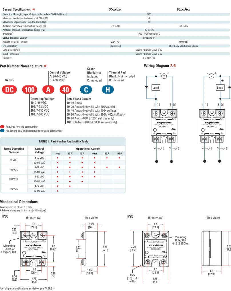
Series
Operating Voltage
60:
7-48 VDC
100:
7-72 VDC
200:
7-150 VDC
400:
7-300 VDC
Thermal Pad
Blank:
Not Included
H:
Included
Control Voltage
A:
90-140 VAC
D:
4-32 VDC
Cover
Blank:
Not
Included
C:
Included
Rated Load Current
10:
10 Amps
20:
20 Amps (Not valid with 400A suffix)
40:
40 Amps (Not valid with 400x suffixes)
60:
60 Amps (Not valid with 200A, 400x suffixes)
80:
80 Amps (60D & 100D suffixes only)
100:
100 Amps (60D & 100D suffixes only)
DC
100
A
40
C
H
Mechanical Dimensions
Part Number Nomenclature
Tolerances: ±0.02 in / 0.5 mm All dimensions are in: inches [millimeters]
(E) Not all part combinations available, see TABLE 1. (F) Inductive loads must be diode supressed as indicated.
(G) Load can be wired to either terminal 1 or terminal 2. Proper polarity must be observed all the time for the power supply and load with terminal 2 being positive with respect to terminal 1.
Required for valid part number
For options only and not required for valid part number
Wiring Diagram
(F, G) V+
+
-Load
1 4 2+ 3+ S O L I D S T A T E R E L A Y OUTPUT INPUT DCXXXXXX1 (–)
2 (+)
4 (– / )
3 (+ / )
Load
V+
+
-1 4 2+ 3+ S O L I D S T A T E R E L A Y OUTPUT INPUT DCXXXXXX4 (– / )
3 (+ / )
1 (–)
2 (+)
IP00
IP20
1.05 [26.8] 0.79 [20.1] 2.26 [57.3] 1.22 [31] 1.3 [32.9] 2.25 [57.2] 1.0 [25.4] 1.1 [27.9] 1.7 [43.2] 1.75 [44.5] 0.33 [8.3] 0.38 [9.5] 0.28 [7] 1 4 2+ 3+ S O L I D S T A T E R E L A Y OUTPUT INPUT DCXXXXXX Mounting Hole/Slot 0.19 [4.9] DIA. 1.75 [44.5] 2.29 [58.21 1.0 [25.4] 1.1 [27.9] 0.25 [6.3] DIA. (4PL) Mounting Hole/Slot 0.19 [4.9] DIA. 1 4 2+ 3+ S O L I D S T A T E R E L A Y OUTPUT INPUT DCXXXXXXDCxxx
D
xx
DCxxx
A
xx
General SpecificationsDielectric Strength, Input-Output to Baseplate (50/60Hz) [Vrms] Minimum Insulation Resistance (@ 500 VDC)
Maximum Capacitance, Input to Output [pF] Ambient Operating Temperature Range [ºC] Ambient Storage Temperature Range [ºC] IP ratings
Status Indicator Display
Input Terminals
Humidity 5 to 85% HR
Screw / Combo Drive 6-32 10 -30 to 80
Green (On) IP00 / IP20 for suffix C
2500
-40 to 125 109
-20 to 65 (A)
Weight (typical) [oz] (gr) Encapsulation
2.64 (75) 2.992 (85)
Epoxy Free Thermally Conductive Epoxy
Output Terminals Screw / Combo Drive 8-32
Rated Operating
Voltage VoltageControl 10 A 20 A Operational Current40 A 60 A 80 A 100 A
60 VDC 4-32 VDC 90-140 VAC 4-32 VDC 90-140 VAC 4-32 VDC 90-140 VAC 4-32 VDC 90-140 VAC 100 VDC 200 VDC 400 VDC
TABLE 1. Part Number Availability Table
(Front view) (Side view) (Front view) (Side view)
DC Series
Complete specifications of these & other Crydom products available at:
www.crydom.com
2/+
1/-3/+A1
4/-A2
Input Control Circuit Output Control Status IndicatorBlock Diagram
Switching Time Diagram
(H) Thermal pad and IP20 plastic cover are available as options for this family. See Part Number Nomenclature for information on how to order them.
(J)Compatible with IP00 versions only. DC Series Part No. Heat Sinks TRM1 TRM6 HK1 HS501DR HS351 HS351DR HS202DRHS202 HS201DRHS201 HS151DRHS151 HS103DRHS103 HS053 5.0º 3.5º 2.0º 2.0º 1.5º 1.0º 0.5º DC
60
x10 / DC100
x10 DC60
x20 / DC100
x20 DC60
x40 / DC100
x40 DC60
x60 / DC100
x60 DC60
D80 / DC100
D80 DC60
D100 / DC100
D100 DC200
x10 DC200
x20 DC200
x40 DC200
D60 DC400
x10 DC400
x20TABLE 2. Compatible Accessories
(H)(J)
V
CTRLV
OUTtod
tfd
tfs
tos
Derating Curves
DC
Input
40 30 20 10 20 30 40 50 60 70 80 0 Ambient Temperature (ºC)Load Current (Amps)
DC
60
D40 1.5ºC/W 3.5ºC/W 5ºC/W 20 15 10 5 20 30 40 50 60 70 80 0 Ambient Temperature (ºC)Load Current (Amps)
DC
60
D20 5ºC/W 10 8 6 4 2 20 30 40 50 60 70 80 0 Ambient Temperature (ºC)Load Current (Amps)
DC
60
D105ºC/W
Turn-On Time Maximum = tod + tos Turn-Off Time Maximum = tfd + tfs
DC Series
40 30 20 10 20 30 40 50 60 70 80 0 Ambient Temperature (ºC)Load Current (Amps)
DC
100
D40 1.5ºC/W 3.5ºC/W 5ºC/W 20 15 10 5 20 30 40 50 60 70 80 0 Ambient Temperature (ºC)Load Current (Amps)
DC
100
D20 5ºC/W 10 8 6 4 2 20 30 40 50 60 70 80 0 Ambient Temperature (ºC)Load Current (Amps)
DC
100
D10 5ºC/W 80 60 40 20 20 30 40 50 60 70 80 0 Ambient Temperature (ºC)Load Current (Amps)
DC
100
D80 0.5ºC/W 1.5ºC/W 3.5ºC/W 5ºC/W 60 40 20 20 30 40 50 60 70 80 0 Ambient Temperature (ºC)Load Current (Amps)
DC
100
D60 1ºC/W 2ºC/W 5ºC/W 80 100 60 40 20 20 30 40 50 60 70 80 0 Ambient Temperature (ºC)Load Current (Amps)
DC
100
D100 0.5ºC/W 1.5ºC/W 3.5ºC/W 5ºC/W 40 30 20 10 20 30 40 50 60 70 80 0 Ambient Temperature (ºC)Load Current (Amps)
DC
200
D40 1ºC/W 2C/W 5ºC/W 20 15 10 5 20 30 40 50 60 70 80 0 Ambient Temperature (ºC)Load Current (Amps)
DC
200
D20 2ºC/W 3.5ºC/W 5ºC/W 10 8 6 4 2 20 30 40 50 60 70 80 0 Ambient Temperature (ºC)Load Current (Amps)
DC
200
D10 5ºC/W 20 15 10 5 20 30 40 50 60 70 80 0 Ambient Temperature (ºC)Load Current (Amps)
DC
400
D20 0.5ºC/W 1ºC/W 2ºC/W 5ºC/W 60 40 20 20 30 40 50 60 70 80 0 Ambient Temperature (ºC)Load Current (Amps)
DC
200
D60 0.5ºC/W 2ºC/W 3.5ºC/W 5ºC/W 8 10 6 4 2 20 30 40 50 60 70 80 0 Ambient Temperature (ºC)Load Current (Amps)
DC
400
D10 1.5ºC/W 3.5ºC/W 5ºC/W 80 60 40 20 20 30 40 50 60 70 80 0 Ambient Temperature (ºC)Load Current (Amps)
DC
60
D80 0.5ºC/W 1.5ºC/W 3.5ºC/W 5ºC/W 60 40 20 20 30 40 50 60 70 80 0 Ambient Temperature (ºC)Load Current (Amps)
DC
60
D60 1ºC/W 2ºC/W 5ºC/W 80 100 60 40 20 20 30 40 50 60 70 80 0 Ambient Temperature (ºC)Load Current (Amps)
DC
60
D100DC Series
Complete specifications of these & other Crydom products available at:
www.crydom.com
60 40 20 20 25 30 35 40 45 50 55 60 65 0 Ambient Temperature (ºC)Load Current (Amps)
DC
100
A60 1ºC/W 2ºC/W 5ºC/W 40 30 20 10 20 25 30 35 40 45 50 55 60 65 0 Ambient Temperature (ºC)Load Current (Amps)
DC
100
A40 1.5ºC/W 3.5ºC/W 5ºC/WDerating Curves
AC
Input
20 15 10 20 25 30 35 40 45 50 55 60 65 0 Ambient Temperature (ºC)Load Current (Amps)
DC
400
A20 0.5ºC/W 1ºC/W 2ºC/W 5ºC/W 5 10 8 6 4 2 20 25 30 35 40 45 50 55 60 65 0 Ambient Temperature (ºC)Load Current (Amps)
DC
60
A10 5ºC/W 20 15 10 5 20 25 30 35 40 45 50 55 60 65 0 Ambient Temperature (ºC)Load Current (Amps)
DC
60
A20 5ºC/W 10 8 6 4 20 25 30 35 40 45 50 55 60 65 0 Ambient Temperature (ºC)Load Current (Amps)
DC
100
A10 5ºC/W 2 40 30 20 10 20 25 30 35 40 45 50 55 60 65 0 Ambient Temperature (ºC)Load Current (Amps)
DC
60
A40 1.5ºC/W 3.5ºC/W 5ºC/W 20 15 10 5 20 25 30 35 40 45 50 55 60 65 0 Ambient Temperature (ºC)Load Current (Amps)
DC
100
A20 5ºC/W 60 40 20 20 25 30 35 40 45 50 55 60 65 0 Ambient Temperature (ºC)Load Current (Amps)
DC
60
A60 1ºC/W 2ºC/W 5ºC/W 10 8 6 4 20 25 30 35 40 45 50 55 60 65 0 Ambient Temperature (ºC)Load Current (Amps)
DC
200
A10 5ºC/W 2 20 15 10 5 20 25 30 35 40 45 50 55 60 65 0 Ambient Temperature (ºC)Load Current (Amps)
DC
200
A20 2ºC/W 3.5ºC/W 5ºC/W 40 30 20 10 20 25 30 35 40 45 50 55 60 65 0 Ambient Temperature (ºC)Load Current (Amps)
DC
200
A40 1ºC/W 2ºC/W 5ºC/W 10 8 6 2 20 25 30 35 40 45 50 55 60 65 0 Ambient Temperature (ºC)Load Current (Amps)
DC
400
A101.5ºC/W 3.5ºC/W 5ºC/W
AMERICA
United States & CanadaCrydom Inc
2320 Paseo de las Americas, Suite 201 San Diego, CA 92154 Sales Support: Tel.: +1 (877) 502 5500 Fax: +1 (619) 210 1590 [email protected] Technical Support: Tel.: +1 (877) 702 7700 [email protected] Mexico Automatismo Crouzet S.A. de C.V.
Calzada Zavaleta 2505-C Col Sta Cruz Buenavista C.P. 72150 - Puebla Sales Support: Toll free: 01 800 087 6333 Tel. : +52 (222) 409 7000 Fax : +52 (222) 409 7810 [email protected]
Southern & Central
American Countries CST Latinoamerica
Alameda Rio Negro, 1030, 18º andar – Conjunto 1803 CEP: 06454-000 Barueri - São Paulo Brasil
Tel.: +55 (11) 2505 7500 Fax: +55 (11) 2505 7507
EUROPE, MIDDLE EAST
& AFRICA
United Kingdom
Crydom SSR Ltd
Arena Business Centre Holyrood, Close Poole, Dorset BH17 7FJ Sales Support Tel.: +44 (0) 1202 606030 Fax: +44 (0) 1202 606035 [email protected] Tech Support [email protected]
Austria & Switzerland Tel.: +44 (0) 1202 606030 Fax: +44 (0) 1202 606035 [email protected] Belgium Tel.: +32 (0) 2 460 4413 Fax: +32 (0) 2 461 2614 [email protected] France Tel.: +33 (0) 810 123 963 Fax: +33 (0) 810 057 605 [email protected] Germany Tel.: +49 (0) 180 3000 506 Fax: +49 (0) 180 3205 227 [email protected] Italy Tel.: +39 (0) 2 665 99 260 Fax: +39 (0) 2 665 99 268 [email protected] Spain Tel.: +34 902 876 217 Fax: +34 902 876 219 [email protected] Netherlands Tel.: +31 (0) 71 582 0068 Fax: +31 (0) 71 542 1648 [email protected] Middle East,
Africa & Other European Countries
Tel. : +44 (0) 1202 606030 Fax: +44 (0) 1202 606035
ASIA PACIFIC
China & Hong KongCustom Sensors & Technologies Asia
Taiwan & Japan
Custom Sensors & Technologies
India
(Shanghai) Ltd.
13th floor
Chang Feng International Tower
89 Yunling Road (East) Putuo District Shanghai, 200062 Sales Support Tel.: +86 (0) 21 6065 7725 Fax: +86 (0) 21 6065 7749 [email protected] Tech Support [email protected]
2F, No. 39, Ji-Hu Road Nei-Hu Dist. Taipei 114 Tel: +886 2 8751 6388 Fax: +886 2 2657 8725 [email protected] South Korea
Custom Sensors & Technologies 2F, Jeil Bldg., 94-46 Youngdeungpo-dong 7-ga Youngdeungpo-gu, Seoul, 150-037 Tel.: +82 2 2629 8312 Fax: +82 2 2629 8310 [email protected]
South East Asian & Pacific Countries
Custom Sensors & Technologies
2F, No. 39, Ji-Hu Road Nei-Hu Dist. Taipei 114, Taiwan Tel.: +886 2 8751 6388 ext.131 Fax: +886 2 2657 8725 [email protected] CST Sensors India Pvt Ltd
4th Floor, Trident Towers, No. 23, 100 Ft- Ashoka Pillar Road, 2nd Block, Jayanagar,
Bangalore- 560011 Tel: +91 (80) 4113 2204 /05 Fax: +91 (80) 4113 2206
© 2011 Crydom Inc., All Rights Reserved.
Specifications are subject to change without prior notice. Crydom and the Crydom logo are registered trademarks of Crydom Inc.