User Manual
www.doughty-engineering.co.uk www.doughty-engineering.co.ukStudio Rail
Size 60
Version 11.0Contents www.doughty-engineering.co.uk Contents: Introduction ... 2 Exclusion of Liability ... 2 Safety Instructions ... 2
Rail Loading Charts ...3-4 Operating Data ...5 - 10 1. Selecting the correct carriage. ...5 - 7 2. Mounting carriages on Studio Rail... 7
3. Moving carriages on Studio Rail. ... 8
4. Fitting equipment to different carriages ... 9
5. Using Double Swivel Carriages ... 10
Maintenance ... 11
Repairs ... 11
Contact Details ... 11
EC Declaration of Conformity ... 12
www.doughty-engineering.co.uk
Introduction
Studio Rail is an extruded aluminium rail system equipped with sliding carriages. The
carriages are designed to support a variety of fittings, typically luminaires and curtains/
drapes. Studio Rail is available in straight lengths from two to six metres and six radius curves.
Exclusion of Liability
Using this product for any other purpose than described in this manual is considered contrary to its designated use and the manufacturer cannot be held liable for any damage resulting from such use.
Safety Instructions
1. Studio Rail has a SWL of 100 Kg per 1500mm suspension points unless arranged otherwise by a qualified person in liaison with Doughty Engineering Ltd.
In the event that a customer requests to change the loading specifications,
agreement must be reached with Doughty Engineering Ltd to raise an ‘Authorised Safe Working Load’ Certificate.
2. When using Studio Rail accessories care must be taken not to exceed the SWL of the component or the SWL of the Studio Rail Structure.
3. It is recommended that Safety Bonds are used with this equipment. When Safety Bonds are used responsibility for the following lies with the user:
i) The Safety Bond is of optimum length, i.e. in the event of failure, the ‘drop’ distance is kept as short as possible.
ii) The Safety Bond is attached such that the mounting points are of sufficient strength to withstand the forces imposed by the falling load.
2
↓
↓
Maximum distance between supports = 1500mm
3
www.doughty-engineering.co.uk Load Graphs↓
D1
2.0m 1.5m 1.0m 0.0m 8 10mm 50Kg 100Kg 150Kg 6 4 2 0mm Deflection Distance between suspension points (D1) Load 1 3 5 7 9Fixed Rail - Load between two suspension points
↓
250mm
0.25m 0.0m 8 10mm 50Kg 100Kg 150Kg 6 4 2 0mm Deflection Cantilever 1 3 5 7 9Fixed Rail - Cantilever
Max recomended SWL:
4
www.doughty-engineering.co.uk Load Graphs
↓
↓
50mm Max
Fixed Rail - Rail Joint Loading
1.0m
1.5m
500mm SWL 100 Kg SWL 75 Kg250mm SWL 25 Kg250mm 250mm SWL 75 Kg 250mm SWL 25 Kg↓
↓
Moving Rail Loading
Studio Rail Joints should be supported as illustrated
Unsupported joints must be treated as a pair of Cantilevers
Operating Data
www.doughty-engineering.co.uk
1. Selecting the correct carriages a. T84220 - Cable Carriage
The cable carriage is designed to support cables used with luminaires etc on the studio rails. The cable carriage is supplied with a Cable Tie Saddle. Fig 1
b. T84225 - Curtain Carriage - SWL 6 Kg
Curtain Carriages are used to suspend Curtains/Drapes. This carriage has a SWL
of 6 Kg each and is recommended to be used at 300mm intervals. Fig 2
c. T84230 - Cupped Curtain Brake.
The Cupped Curtain Brake is typically used to hold or tension one or both ends of
a Curtain/Drape. This brake is fitted with a pole operated cup. Fig 3
Fig 1
Fig 2
Fig 3
Operating Data
www.doughty-engineering.co.uk
d. T84185 - 4 Wheel Carriage - 16mm Spigot - SWL 50 Kg
This carriage is typically used to suspend luminaires etc fitted with a 16mm Receiver and is fitted with a friction brake as standard. Fig 4
e. T84185 - 4 Wheel Carriage - 16mm Mini Spigot - SWL 50 Kg
This carriage is typically used to suspend luminaires etc fitted with a 16mm Receiver and is fitted with a friction brake as standard. Fig 5
f. T84205 - 6 Wheel Carriage - 28mm Receiver - SWL 100 Kg
This carriage is typically used to suspend luminaires etc fitted with a 28mm Spigot and is fitted with a friction brake as standard. Fig 6
Fig 4
Fig 5
Fig 6
Operating Data
www.doughty-engineering.co.uk
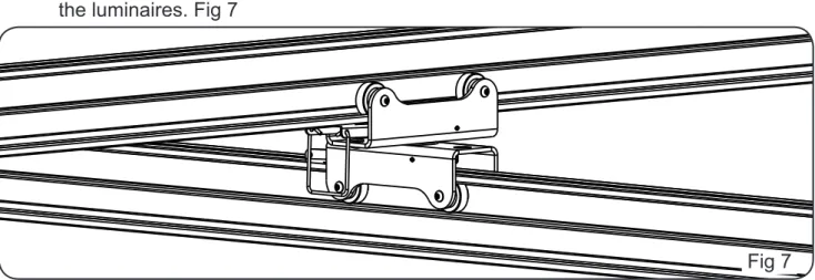
g. T84215 - 4 Wheel Double Swivel Carriage - SWL 75 Kg
The Double Swivel Carriage enables two rails to be mounted on top of one another and is ideal for use where two parallel rails are installed with moving rails to suspend the luminaires. Fig 7
2. Mounting carriages on Studio Rail
Carriages are mounted on Studio Rail by sliding the wheels into the lower section of the
rail, as shown. Fig 8
NB: Prior to fitting the carriages, consideration must be given to fitting ‘End Stops’ on the
rails such that the front and rear carriages are prevented from traversing off the end of the rails. Figs 8 & 9
Fig 7 Fig 8 Fig 9 End Stop End Stop
7
Operating Data
www.doughty-engineering.co.uk
3. Moving the Carriages Carriages with Friction Brake.
Carriages with a friction brake can be traversed using a operators pole.
Carriages can be positioned using the operators pole hook to release the friction brake loop. Final adjustment can be achieved by pushing the carriages. Fig 10
The friction brake serves to prevent the carriages running freely. Carriages with Pole Cup Brake.
Carriages with a Pole Cup Brake can be moved by turning the Pole Cup to release the brake using an operators pole. The carriages can then be moved into position and the brake reapplied with the operators pole. Fig 11
Fig 10
Fig 11 Friction Brake Loop
Operators Pole
Operators Pole Pole Cup Brake
Operating Data
www.doughty-engineering.co.uk
4. Fitting equipment to different carriages
Carriages fitted with a 16mm Spigot are designed to accept equipment fitted with a 16mm
Receiver. The Spigot has a machined groove to accommodate the locking screw in the receiver.
Carriages fitted with a 28mm Spigot are designed to accept equipment fitted with a 28mm
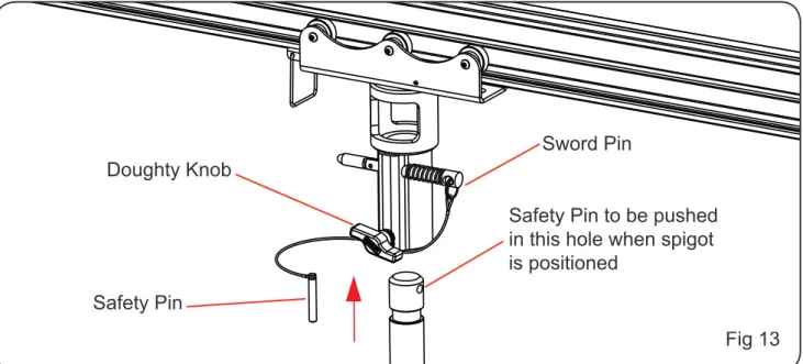
Spigot. The receiver has 3 safety points incorporated in its design.
The first point is the safety pin, this pin is designed to take the initial weight of the
equipment being suspended. The second point is the sword pin, this pin secures the spigot in the receiver and still allows the spigot to rotate. The third point is the Doughty Knob, this
stops the spigot rotating in the receiver.
Fig 12
Fig 13 Machined Groove
Doughty Knob
Safety Bond Point
Sword Pin 16mm Receiver
Safety Pin
Safety Pin to be pushed in this hole when spigot is positioned
Operating Data
www.doughty-engineering.co.uk
5. Using Double Swivel Carriages
Double swivel carriages are designed to be used in pairs mounting a moving rail to a pair of parallel rails. Fig 14
The moving rail can be positioned using the operators pole hook to release the friction brake loop on the Double Swivel Carriages. Final adjustment can be achieved by pushing the carriages. Fig 15
End stops must be fitted in the upper section of the moving rail to stop the rail sliding
through the Double Swivel Carriages and becoming dismounted.
End stops are also fitted to the lower section of the moving rail to stop equipment from
traversing off the end of the rails.
The friction brake serves to prevent the carriages running freely.
10
Fig 15 Fig 14 Parallel Rails End Stops Double Swivel Carriages Moving Rail End StopsMaintenance & Repairs
www.doughty-engineering.co.uk
Maintenance
Do not oil or grease any components of rails.
A 100% proof load test must be carried out by a qualified person at the following intervals:
During initial commissioning
•
After each reassembly
•
Annually
•
Testing Tasks include:
Inspect rail suspension points
•
Ensure carriages run freely and brakes are operational
•
Check all safety devices are complete and serviceable
•
Repairs
Repair may only be carried out by competent personnel trained by Doughty Engineering Ltd or an approved service agent as listed on the Doughty Web Site.
Only Doughty replacement parts should be used. Contact Details
11
Doughty Engineering Ltd
Crow Arch Lane
Ringwood, Hampshire, BH24 1NZ
Tel: +44 (0) 1425 478961 Fax: +44 (0) 1425 474481
email: [email protected]
Web: www.doughty-engineering.co.uk
Note: Whilst every effort has been made to ensure that the information contained within this manual is correct, Doughty Engineering does not accept any liability for errors or omissions. Specifications and technical data are intended for guidance purposes only and may vary.
www.doughty-engineering.co.uk Declaration of Conformity
12
EC DECLARATION OF CONFORMITYDoughty Engineering Limited hereby certify that the equipment stated below has
been designed to comply with all relevant sections of the specifications referenced
below and complies with all applicable Essential Requirements of the EC Directives and amendments and the National Laws and Regulations adopting these Directives. Description: Studio Rail - Size 60 Is in conformity with the provisions of the following
EC Directives:
Machinery Directive 98/37/EEC
Harmonised Standards:
BS EN 292:Part 1:1991 BS EN 292:Part 2:1991 BS EN ISO 9001:1994 BS EN 755-2
National Technical Standards & Specifications:
BS 7905-1:2001 BS 1615 BS 1474
Signed: Date: 25-04-08
Name: Nigel Curtis Position: Technical Director Being the responsible person appointed by the manufacturer.
08
DEQ 083 Rev 4Doughty Engineering Ltd Crow Arch Lane, Ringwood, Hampshire, BH24 1NZ
Tel: +44 (0) 1425 478961 Fax: +44 (0) 1425 474481 Web: www.doughty-engineering.co.uk email: [email protected]
Company Registration No. London 972614
Registered Office: Crow Arch Lane, Ringwood, Hants, BH24 1NZ Directors: M.B. Lister, J.C.G. Chiverton, N.D. Curtis, S.C. Wright