The OpenGL
RGraphics System:
A Specification
(Version 3.1 - March 24, 2009)
Mark Segal Kurt Akeley
Editor (version 1.1): Chris Frazier Editor (versions 1.2-3.1): Jon Leech
Copyright c2006-2009 The Khronos Group Inc. All Rights Reserved.
This specification is protected by copyright laws and contains material proprietary to the Khronos Group, Inc. It or any components may not be reproduced, repub-lished, distributed, transmitted, displayed, broadcast or otherwise exploited in any manner without the express prior written permission of Khronos Group. You may use this specification for implementing the functionality therein, without altering or removing any trademark, copyright or other notice from the specification, but the receipt or possession of this specification does not convey any rights to reproduce, disclose, or distribute its contents, or to manufacture, use, or sell anything that it may describe, in whole or in part.
Khronos Group grants express permission to any current Promoter, Contributor or Adopter member of Khronos to copy and redistribute UNMODIFIED versions of this specification in any fashion, provided that NO CHARGE is made for the specification and the latest available update of the specification for any version of the API is used whenever possible. Such distributed specification may be re-formatted AS LONG AS the contents of the specification are not changed in any way. The specification may be incorporated into a product that is sold as long as such product includes significant independent work developed by the seller. A link to the current version of this specification on the Khronos Group web-site should be included whenever possible with specification distributions.
Khronos Group makes no, and expressly disclaims any, representations or war-ranties, express or implied, regarding this specification, including, without limita-tion, any implied warranties of merchantability or fitness for a particular purpose or non-infringement of any intellectual property. Khronos Group makes no, and expressly disclaims any, warranties, express or implied, regarding the correctness, accuracy, completeness, timeliness, and reliability of the specification. Under no circumstances will the Khronos Group, or any of its Promoters, Contributors or Members or their respective partners, officers, directors, employees, agents or rep-resentatives be liable for any damages, whether direct, indirect, special or conse-quential damages for lost revenues, lost profits, or otherwise, arising from or in connection with these materials.
Contents
1 Introduction 1
1.1 What is the OpenGL Graphics System? . . . 1
1.2 Programmer’s View of OpenGL . . . 1
1.3 Implementor’s View of OpenGL . . . 2
1.4 Our View . . . 2
1.5 The Deprecation Model . . . 3
1.6 Companion Documents . . . 3
1.6.1 OpenGL Shading Language . . . 3
1.6.2 Window System Bindings . . . 3
2 OpenGL Operation 5 2.1 OpenGL Fundamentals . . . 5
2.1.1 Floating-Point Computation . . . 7
2.1.2 16-Bit Floating-Point Numbers . . . 8
2.1.3 Unsigned 11-Bit Floating-Point Numbers . . . 8
2.1.4 Unsigned 10-Bit Floating-Point Numbers . . . 9
2.1.5 Fixed-Point Data Conversions . . . 10
2.2 GL State . . . 12
2.2.1 Shared Object State . . . 13
2.3 GL Command Syntax . . . 13
2.4 Basic GL Operation . . . 15
2.5 GL Errors . . . 18
2.6 Primitives and Vertices . . . 19
2.6.1 Primitive Types . . . 21
2.7 Vertex Specification . . . 23
2.8 Vertex Arrays . . . 24
2.8.1 Transferring Array Elements . . . 26
2.8.2 Drawing Commands . . . 27
CONTENTS ii
2.9.1 Mapping and Unmapping Buffer Data . . . 34
2.9.2 Effects of Accessing Outside Buffer Bounds . . . 38
2.9.3 Copying Between Buffers . . . 39
2.9.4 Vertex Arrays in Buffer Objects . . . 39
2.9.5 Array Indices in Buffer Objects . . . 40
2.9.6 Buffer Object State . . . 40
2.10 Vertex Array Objects . . . 41
2.11 Vertex Shaders . . . 42
2.11.1 Shader Objects . . . 42
2.11.2 Program Objects . . . 44
2.11.3 Vertex Attributes . . . 46
2.11.4 Uniform Variables . . . 49
2.11.5 Samplers . . . 64
2.11.6 Varying Variables . . . 65
2.11.7 Shader Execution . . . 67
2.11.8 Required State . . . 72
2.12 Coordinate Transformations . . . 74
2.12.1 Controlling the Viewport . . . 74
2.13 Asynchronous Queries . . . 75
2.14 Conditional Rendering . . . 77
2.15 Transform Feedback . . . 78
2.16 Primitive Queries . . . 81
2.17 Primitive Clipping . . . 82
2.17.1 Clipping Shader Varying Outputs . . . 83
3 Rasterization 85 3.1 Discarding Primitives Before Rasterization . . . 86
3.2 Invariance . . . 86
3.3 Antialiasing . . . 87
3.3.1 Multisampling . . . 88
3.4 Points . . . 89
3.4.1 Basic Point Rasterization . . . 90
3.4.2 Point Rasterization State . . . 91
3.4.3 Point Multisample Rasterization . . . 91
3.5 Line Segments . . . 92
3.5.1 Basic Line Segment Rasterization . . . 92
3.5.2 Other Line Segment Features . . . 94
3.5.3 Line Rasterization State . . . 95
3.5.4 Line Multisample Rasterization . . . 96
CONTENTS iii
3.6.1 Basic Polygon Rasterization . . . 96
3.6.2 Antialiasing . . . 99
3.6.3 Options Controlling Polygon Rasterization . . . 99
3.6.4 Depth Offset . . . 100
3.6.5 Polygon Multisample Rasterization . . . 101
3.6.6 Polygon Rasterization State . . . 101
3.7 Pixel Rectangles . . . 102
3.7.1 Pixel Storage Modes and Pixel Buffer Objects . . . 102
3.7.2 Transfer of Pixel Rectangles . . . 103
3.8 Texturing . . . 115
3.8.1 Texture Image Specification . . . 116
3.8.2 Alternate Texture Image Specification Commands . . . . 128
3.8.3 Compressed Texture Images . . . 135
3.8.4 Buffer Textures . . . 139
3.8.5 Texture Parameters . . . 140
3.8.6 Depth Component Textures . . . 142
3.8.7 Cube Map Texture Selection . . . 142
3.8.8 Texture Minification . . . 144
3.8.9 Texture Magnification . . . 153
3.8.10 Combined Depth/Stencil Textures . . . 153
3.8.11 Texture Completeness . . . 154
3.8.12 Texture State and Proxy State . . . 155
3.8.13 Texture Objects . . . 157
3.8.14 Texture Comparison Modes . . . 158
3.8.15 sRGB Texture Color Conversion . . . 160
3.8.16 Shared Exponent Texture Color Conversion . . . 160
3.9 Fragment Shaders . . . 161
3.9.1 Shader Variables . . . 161
3.9.2 Shader Execution . . . 162
3.10 Antialiasing Application . . . 166
3.11 Multisample Point Fade . . . 166
4 Per-Fragment Operations and the Framebuffer 167 4.1 Per-Fragment Operations . . . 168
4.1.1 Pixel Ownership Test . . . 169
4.1.2 Scissor Test . . . 169
4.1.3 Multisample Fragment Operations . . . 170
4.1.4 Stencil Test . . . 171
4.1.5 Depth Buffer Test . . . 173
CONTENTS iv
4.1.7 Blending . . . 174
4.1.8 sRGB Conversion . . . 179
4.1.9 Dithering . . . 179
4.1.10 Logical Operation . . . 180
4.1.11 Additional Multisample Fragment Operations . . . 181
4.2 Whole Framebuffer Operations . . . 182
4.2.1 Selecting a Buffer for Writing . . . 182
4.2.2 Fine Control of Buffer Updates . . . 186
4.2.3 Clearing the Buffers . . . 188
4.3 Reading and Copying Pixels . . . 190
4.3.1 Reading Pixels . . . 190
4.3.2 Copying Pixels . . . 197
4.3.3 Pixel Draw/Read State . . . 199
4.4 Framebuffer Objects . . . 200
4.4.1 Binding and Managing Framebuffer Objects . . . 200
4.4.2 Attaching Images to Framebuffer Objects . . . 203
4.4.3 Feedback Loops Between Textures and the Framebuffer . 210 4.4.4 Framebuffer Completeness . . . 212
4.4.5 Effects of Framebuffer State on Framebuffer Dependent Values . . . 217
4.4.6 Mapping between Pixel and Element in Attached Image . 218 5 Special Functions 219 5.1 Flush and Finish . . . 219
5.2 Hints . . . 219
6 State and State Requests 221 6.1 Querying GL State . . . 221
6.1.1 Simple Queries . . . 221
6.1.2 Data Conversions . . . 222
6.1.3 Enumerated Queries . . . 223
6.1.4 Texture Queries . . . 225
6.1.5 String Queries . . . 227
6.1.6 Asynchronous Queries . . . 228
6.1.7 Buffer Object Queries . . . 230
6.1.8 Vertex Array Object Queries . . . 231
6.1.9 Shader and Program Queries . . . 232
6.1.10 Framebuffer Object Queries . . . 236
6.1.11 Renderbuffer Object Queries . . . 238
CONTENTS v
A Invariance 281
A.1 Repeatability . . . 281
A.2 Multi-pass Algorithms . . . 282
A.3 Invariance Rules . . . 282
A.4 What All This Means . . . 283
B Corollaries 285 C Compressed Texture Image Formats 287 C.1 RGTC Compressed Texture Image Formats . . . 287
C.1.1 FormatCOMPRESSED RED RGTC1 . . . 288
C.1.2 FormatCOMPRESSED SIGNED RED RGTC1 . . . 289
C.1.3 FormatCOMPRESSED RG RGTC2 . . . 289
C.1.4 FormatCOMPRESSED SIGNED RG RGTC2 . . . 290
D Shared Objects and Multiple Contexts 291 D.1 Object Deletion Behavior . . . 291
D.2 Propagating State Changes . . . 292
D.2.1 Definitions . . . 293
D.2.2 Rules . . . 293
E The Deprecation Model 295 E.1 Profiles and Deprecated Features of OpenGL 3.0 . . . 295
F Version 3.0 and Before 301 F.1 New Features . . . 301
F.2 Deprecation Model . . . 302
F.3 Changed Tokens . . . 303
F.4 Change Log . . . 303
F.5 Credits and Acknowledgements . . . 305
G Version 3.1 308 G.1 New Features . . . 308
G.2 Deprecation Model . . . 309
G.3 Change Log . . . 309
G.4 Credits and Acknowledgements . . . 309
H Extension Registry, Header Files, and ARB Extensions 312 H.1 Extension Registry . . . 312
H.2 Header Files . . . 312
CONTENTS vi
H.3.1 Naming Conventions . . . 314
H.3.2 Promoting Extensions to Core Features . . . 314
H.3.3 Multitexture . . . 314
H.3.4 Transpose Matrix . . . 315
H.3.5 Multisample . . . 315
H.3.6 Texture Add Environment Mode . . . 315
H.3.7 Cube Map Textures . . . 315
H.3.8 Compressed Textures . . . 315
H.3.9 Texture Border Clamp . . . 315
H.3.10 Point Parameters . . . 315
H.3.11 Vertex Blend . . . 315
H.3.12 Matrix Palette . . . 316
H.3.13 Texture Combine Environment Mode . . . 316
H.3.14 Texture Crossbar Environment Mode . . . 316
H.3.15 Texture Dot3 Environment Mode . . . 316
H.3.16 Texture Mirrored Repeat . . . 316
H.3.17 Depth Texture . . . 316
H.3.18 Shadow . . . 316
H.3.19 Shadow Ambient . . . 317
H.3.20 Window Raster Position . . . 317
H.3.21 Low-Level Vertex Programming . . . 317
H.3.22 Low-Level Fragment Programming . . . 317
H.3.23 Buffer Objects . . . 317
H.3.24 Occlusion Queries . . . 317
H.3.25 Shader Objects . . . 318
H.3.26 High-Level Vertex Programming . . . 318
H.3.27 High-Level Fragment Programming . . . 318
H.3.28 OpenGL Shading Language . . . 318
H.3.29 Non-Power-Of-Two Textures . . . 318
H.3.30 Point Sprites . . . 318
H.3.31 Fragment Program Shadow . . . 318
H.3.32 Multiple Render Targets . . . 319
H.3.33 Rectangular Textures . . . 319
H.3.34 Floating-Point Color Buffers . . . 319
H.3.35 Half-Precision Floating Point . . . 319
H.3.36 Floating-Point Textures . . . 320
H.3.37 Pixel Buffer Objects . . . 320
H.3.38 Floating-Point Depth Buffers . . . 320
H.3.39 Instanced Rendering . . . 320
CONTENTS vii
H.3.41 sRGB Framebuffers . . . 321
H.3.42 Geometry Shaders . . . 321
H.3.43 Half-Precision Vertex Data . . . 321
H.3.44 Instanced Rendering . . . 321
H.3.45 Flexible Buffer Mapping . . . 321
H.3.46 Texture Buffer Objects . . . 321
H.3.47 RGTC Texture Compression Formats . . . 322
H.3.48 One- and Two-Component Texture Formats . . . 322
H.3.49 Vertex Array Objects . . . 322
H.3.50 Versioned Context Creation . . . 322
H.3.51 Restoration of features removed from OpenGL 3.0 . . . . 322
List of Figures
2.1 Block diagram of the GL. . . 15
2.2 Vertex processing and primitive assembly. . . 19
2.3 Triangle strips, fans, and independent triangles. . . 22
3.1 Rasterization. . . 85
3.2 Visualization of Bresenham’s algorithm. . . 93
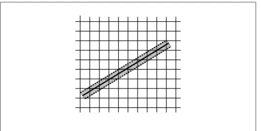
3.3 The region used in rasterizing an antialiased line segment. . . 95
3.4 Transfer of pixel rectangles. . . 103
3.5 Selecting a subimage from an image . . . 108
3.6 A texture image and the coordinates used to access it. . . 128
4.1 Per-fragment operations. . . 169
List of Tables
2.1 GL command suffixes . . . 14
2.2 GL data types . . . 16
2.3 Summary of GL errors . . . 19
2.4 Vertex array sizes (values per vertex) and data types . . . 25
2.5 Buffer object binding targets. . . 31
2.6 Buffer object parameters and their values. . . 31
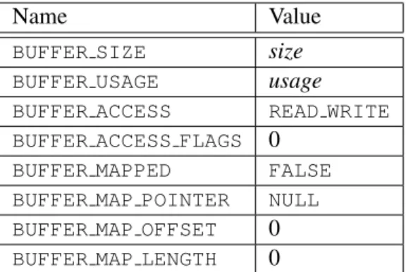
2.7 Buffer object initial state. . . 34
2.8 Buffer object state set byMapBufferRange. . . 36
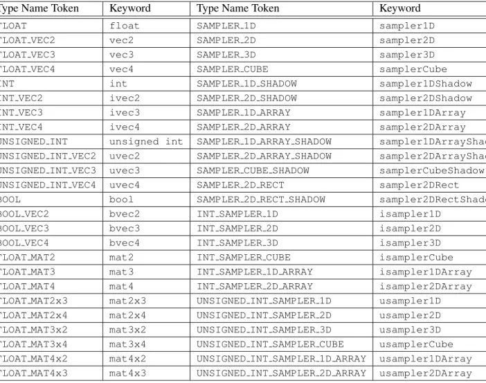
2.9 OpenGL Shading Language type tokens . . . 56
2.10 Transform feedback modes . . . 79
3.1 PixelStoreparameters. . . 103
3.2 Pixel data types. . . 106
3.3 Pixel data formats. . . 107
3.4 Swap Bytes bit ordering. . . 107
3.5 Packed pixel formats. . . 109
3.6 UNSIGNED BYTEformats. Bit numbers are indicated for each com-ponent. . . 110
3.7 UNSIGNED SHORTformats . . . 111
3.8 UNSIGNED INTformats . . . 112
3.9 FLOAT UNSIGNED INTformats . . . 113
3.10 Packed pixel field assignments. . . 114
3.11 Conversion from RGBA, depth, and stencil pixel components to internal texture components. . . 118
3.12 Sized internal color formats. . . 123
3.13 Sized internal depth and stencil formats. . . 124
3.14 Generic and specific compressed internal formats. . . 125
3.15 Internal formats for buffer textures . . . 141
LIST OF TABLES x
3.17 Selection of cube map images. . . 144
3.18 Texel location wrap mode application. . . 148
3.19 Depth texture comparison functions. . . 159
3.20 Correspondence of filtered texture components to texture source components. . . 162
4.1 RGB and Alpha blend equations. . . 177
4.2 Blending functions. . . 178
4.3 Arguments toLogicOpand their corresponding operations. . . 181
4.4 Buffer selection for the default framebuffer . . . 184
4.5 Buffer selection for a framebuffer object . . . 184
4.6 DrawBuffersbuffer selection for the default framebuffer . . . 184
4.7 PixelStoreparameters. . . 192
4.8 ReadPixelsindex masks. . . 195
4.9 ReadPixelsGL data types and reversed component conversion for-mulas. . . 196
4.10 Correspondence of renderbuffer sized to base internal formats. . . 205
4.11 Framebuffer attachment points. . . 207
5.1 Hint targets and descriptions . . . 220
6.1 Texture, table, and filter return values. . . 226
6.2 State Variable Types . . . 240
6.3 Vertex Array Object State (cont.) . . . 241
6.4 Vertex Array Object State (cont.) . . . 242
6.5 Vertex Array Data (not in Vertex Array objects) . . . 243
6.6 Buffer Object State . . . 244
6.7 Transformation state . . . 245
6.8 Coloring . . . 246
6.9 Rasterization . . . 247
6.10 Rasterization (cont.) . . . 248
6.11 Multisampling . . . 249
6.12 Textures (state per texture unit and binding point) . . . 250
6.13 Textures (state per texture object) . . . 251
6.14 Textures (state per texture image) . . . 252
6.15 Texture Environment and Generation . . . 253
6.16 Pixel Operations . . . 254
6.17 Pixel Operations (cont.) . . . 255
6.18 Framebuffer Control . . . 256
LIST OF TABLES xi
6.20 Framebuffer (state per framebuffer object) . . . 258
6.21 Framebuffer (state per attachment point) . . . 259
6.22 Renderbuffer (state per target and binding point) . . . 260
6.23 Renderbuffer (state per renderbuffer object) . . . 261
6.24 Pixels . . . 262
6.25 Shader Object State . . . 263
6.26 Program Object State . . . 264
6.27 Program Object State (cont.) . . . 265
6.28 Program Object State (cont.) . . . 266
6.29 Program Object State (cont.) . . . 267
6.30 Vertex Shader State . . . 268
6.31 Query Object State . . . 269
6.32 Transform Feedback State . . . 270
6.33 Hints . . . 271
6.34 Implementation Dependent Values . . . 272
6.35 Implementation Dependent Values (cont.) . . . 273
6.36 Implementation Dependent Values (cont.) . . . 274
6.37 Implementation Dependent Values (cont.) . . . 275
6.38 Implementation Dependent Values (cont.) . . . 276
6.39 Implementation Dependent Values (cont.) . . . 277
6.40 Implementation Dependent Values (cont.) (1) The minimum value for each stage is MAXstageUNIFORM BLOCKS × MAX stageUNIFORM BLOCK SIZE + MAXstageUNIFORM COMPONENTS . . . 278
6.41 Framebuffer Dependent Values . . . 279
6.42 Miscellaneous . . . 280
Chapter 1
Introduction
This document describes the OpenGL graphics system: what it is, how it acts, and what is required to implement it. We assume that the reader has at least a rudi-mentary understanding of computer graphics. This means familiarity with the es-sentials of computer graphics algorithms as well as familiarity with basic graphics hardware and associated terms.
1.1
What is the OpenGL Graphics System?
OpenGL (for “Open Graphics Library”) is a software interface to graphics hard-ware. The interface consists of a set of several hundred procedures and functions that allow a programmer to specify the objects and operations involved in produc-ing high-quality graphical images, specifically color images of three-dimensional objects.
Most of OpenGL requires that the graphics hardware contain a framebuffer. Many OpenGL calls pertain to drawing objects such as points, lines, and polygons, but the way that some of this drawing occurs (such as when antialiasing is enabled) relies on the existence of a framebuffer. Further, some of OpenGL is specifically concerned with framebuffer manipulation.
1.2
Programmer’s View of OpenGL
To the programmer, OpenGL is a set of commands that allow the specification of geometric objects in two or three dimensions, together with commands that control how these objects are rendered into the framebuffer.
1.3. IMPLEMENTOR’S VIEW OF OPENGL 2
a GL context and associate it with the window. Once a GL context is allocated, the programmer is free to issue OpenGL commands. Some calls are used to draw simple geometric objects (i.e. points, line segments, and polygons), while others affect the rendering of these primitives including how they are lit or colored and how they are mapped from the user’s two- or three-dimensional model space to the two-dimensional screen. There are also calls to effect direct control of the framebuffer, such as reading and writing pixels.
1.3
Implementor’s View of OpenGL
To the implementor, OpenGL is a set of commands that affect the operation of graphics hardware. If the hardware consists only of an addressable framebuffer, then OpenGL must be implemented almost entirely on the host CPU. More typi-cally, the graphics hardware may comprise varying degrees of graphics accelera-tion, from a raster subsystem capable of rendering two-dimensional lines and poly-gons to sophisticated floating-point processors capable of transforming and com-puting on geometric data. The OpenGL implementor’s task is to provide the CPU software interface while dividing the work for each OpenGL command between the CPU and the graphics hardware. This division must be tailored to the available graphics hardware to obtain optimum performance in carrying out OpenGL calls.
OpenGL maintains a considerable amount of state information. This state con-trols how objects are drawn into the framebuffer. Some of this state is directly available to the user: he or she can make calls to obtain its value. Some of it, how-ever, is visible only by the effect it has on what is drawn. One of the main goals of this specification is to make OpenGL state information explicit, to elucidate how it changes, and to indicate what its effects are.
1.4
Our View
1.5. THE DEPRECATION MODEL 3
1.5
The Deprecation Model
GL features marked asdeprecatedin one version of the specification are expected to be removed in a future version, allowing applications time to transition away from use of deprecated features. The deprecation model is described in more detail, together with a summary of the commands and state deprecated from this version of the API, in appendixE.
1.6
Companion Documents
1.6.1 OpenGL Shading Language
This specification should be read together with a companion document titledThe OpenGL Shading Language. The latter document (referred to as the OpenGL Shad-ing Language Specification hereafter) defines the syntax and semantics of the pro-gramming language used to write vertex and fragment shaders (see sections2.11 and3.9). These sections may include references to concepts and terms (such as shading language variable types) defined in the companion document.
OpenGL 3.1 implementations are guaranteed to support at least version 1.30 of the shading language. The actual version supported may be queried as described in section6.1.4.
1.6.2 Window System Bindings
OpenGL requires a companion API to create and manage graphics contexts, win-dows to render into, and other resources beyond the scope of this Specification. There are several such APIs supporting different operating and window systems.
OpenGL Graphics with the X Window System, also called the “GLX Specifica-tion”, describes the GLX API for use of OpenGL in the X Window System. It is primarily directed at Linux and Unix systems, but GLX implementations also exist for Microsoft Windows, MacOS X, and some other platforms where X is avail-able. The GLX Specification is available in the OpenGL Extension Registry (see appendixH).
The WGL API supports use of OpenGL with Microsoft Windows. WGL is documented in Microsoft’s MSDN system, although no full specification exists.
Several APIs exist supporting use of OpenGL with Quartz, the MacOS X win-dow system, including CGL, AGL, and NSOpenGLView. These APIs are docu-mented on Apple’s developer website.
1.6. COMPANION DOCUMENTS 4
EGL implementations may be available supporting OpenGL as well. The EGL Specification is available in the Khronos Extension Registry at URL
Chapter 2
OpenGL Operation
2.1
OpenGL Fundamentals
OpenGL (henceforth, the “GL”) is concerned only with rendering into a frame-buffer (and reading values stored in that frameframe-buffer). There is no support for other peripherals sometimes associated with graphics hardware, such as mice and keyboards. Programmers must rely on other mechanisms to obtain user input.
The GL drawsprimitivessubject to a number of selectable modes and shader programs. Each primitive is a point, line segment, or polygon. Each mode may be changed independently; the setting of one does not affect the settings of oth-ers (although many modes may interact to determine what eventually ends up in the framebuffer). Modes are set, primitives specified, and other GL operations described by sendingcommandsin the form of function or procedure calls.
Primitives are defined by a group of one or more vertices. A vertex defines a point, an endpoint of an edge, or a corner of a polygon where two edges meet. Data such as positional coordinates, colors, normals, texture coordinates, etc. are associated with a vertex and each vertex is processed independently, in order, and in the same way. The only exception to this rule is if the group of vertices must be clipped so that the indicated primitive fits within a specified region; in this case vertex data may be modified and new vertices created. The type of clipping depends on which primitive the group of vertices represents.
2.1. OPENGL FUNDAMENTALS 6
general, the effects of a GL command on either GL modes or the framebuffer must be complete before any subsequent command can have any such effects.
In the GL, data binding occurs on call. This means that data passed to a com-mand are interpreted when that comcom-mand is received. Even if the comcom-mand re-quires a pointer to data, those data are interpreted when the call is made, and any subsequent changes to the data have no effect on the GL (unless the same pointer is used in a subsequent command).
The GL provides direct control over the fundamental operations of 3D and 2D graphics. This includes specification of parameters of application-defined shader programs performing transformation, lighting, texturing, and shading operations, as well as built-in functionality such as antialiasing and texture filtering. It does not provide a means for describing or modeling complex geometric objects. An-other way to describe this situation is to say that the GL provides mechanisms to describe how complex geometric objects are to be rendered rather than mechanisms to describe the complex objects themselves.
The model for interpretation of GL commands is client-server. That is, a gram (the client) issues commands, and these commands are interpreted and pro-cessed by the GL (the server). The server may or may not operate on the same computer as the client. In this sense, the GL is “network-transparent.” A server may maintain a number of GLcontexts, each of which is an encapsulation of cur-rent GL state. A client may choose toconnectto any one of these contexts. Issuing GL commands when the program is notconnectedto acontextresults in undefined behavior.
The GL interacts with two classes of framebuffers: window system-provided and application-created. There is at most one window system-provided framebuffer at any time, referred to as the default framebuffer. Application-created frame-buffers, referred to asframebuffer objects, may be created as desired. These two types of framebuffer are distinguished primarily by the interface for configuring and managing their state.
The effects of GL commands on the default framebuffer are ultimately con-trolled by the window system, which allocates framebuffer resources, determines which portions of the default framebuffer the GL may access at any given time, and communicates to the GL how those portions are structured. Therefore, there are no GL commands to initialize a GL context or configure the default framebuffer. Similarly, display of framebuffer contents on a physical display device (including the transformation of individual framebuffer values by such techniques as gamma correction) is not addressed by the GL.
2.1. OPENGL FUNDAMENTALS 7
Allocation and initialization of GL contexts is also done using these companion APIs. GL contexts can typically be associated with different default framebuffers, and some context state is determined at the time this association is performed.
It is possible to use a GL contextwithouta default framebuffer, in which case a framebuffer object must be used to perform all rendering. This is useful for applications needing to performoffscreen rendering.
The GL is designed to be run on a range of graphics platforms with varying graphics capabilities and performance. To accommodate this variety, we specify ideal behavior instead of actual behavior for certain GL operations. In cases where deviation from the ideal is allowed, we also specify the rules that an implemen-tation must obey if it is to approximate the ideal behavior usefully. This allowed variation in GL behavior implies that two distinct GL implementations may not agree pixel for pixel when presented with the same input even when run on identi-cal framebuffer configurations.
Finally, command names, constants, and types are prefixed in the GL (bygl,
GL, andGL, respectively inC) to reduce name clashes with other packages. The prefixes are omitted in this document for clarity.
2.1.1 Floating-Point Computation
The GL must perform a number of floating-point operations during the course of its operation. In some cases, the representation and/or precision of such opera-tions is defined or limited; by the OpenGL Shading Language Specification for operations in shaders, and in some cases implicitly limited by the specified format of vertex, texture, or renderbuffer data consumed by the GL. Otherwise, the rep-resentation of such floating-point numbers, and the details of how operations on them are performed, is not specified. We require simply that numbers’ floating-point parts contain enough bits and that their exponent fields are large enough so that individual results of floating-point operations are accurate to about1part in
105. The maximum representable magnitude of a floating-point number used to represent positional, normal, or texture coordinates must be at least232; the max-imum representable magnitude for colors must be at least 210. The maximum representable magnitude for all other floating-point values must be at least 232.
x·0 = 0 ·x = 0 for any non-infinite and non-NaN x. 1 ·x = x·1 = x.
x+ 0 = 0 +x=x.00 = 1. (Occasionally further requirements will be specified.) Most single-precision floating-point formats meet these requirements.
2.1. OPENGL FUNDAMENTALS 8
Any representable floating-point value is legal as input to a GL command that requires point data. The result of providing a value that is not a floating-point number to such a command is unspecified, but must not lead to GL interrup-tion or terminainterrup-tion. In IEEE arithmetic, for example, providing a negative zero or a denormalized number to a GL command yields predictable results, while providing a NaN or an infinity yields unspecified results.
Some calculations require division. In such cases (including implied divisions required by vector normalizations), a division by zero produces an unspecified re-sult but must not lead to GL interruption or termination.
2.1.2 16-Bit Floating-Point Numbers
A 16-bit floating-point number has a 1-bit sign (S), a 5-bit exponent (E), and a 10-bit mantissa (M). The valueV of a 16-bit floating-point number is determined by the following:
V =
(−1)S×0.0, E = 0, M = 0 (−1)S×2−14× 2M10, E= 0, M 6= 0
(−1)S×2E−15× 1 +2M10
, 0< E <31
(−1)S×Inf, E = 31, M = 0
NaN, E = 31, M 6= 0
If the floating-point number is interpreted as an unsigned 16-bit integerN, then
S=
N mod 65536
32768
E=
N mod 32768
1024
M =N mod 1024.
Any representable 16-bit floating-point value is legal as input to a GL command that accepts 16-bit floating-point data. The result of providing a value that is not a floating-point number (such asInf orNaN) to such a command is unspecified, but must not lead to GL interruption or termination. Providing a denormalized number or negative zero to GL must yield predictable results.
2.1.3 Unsigned 11-Bit Floating-Point Numbers
2.1. OPENGL FUNDAMENTALS 9
determined by the following:
V =
0.0, E= 0, M = 0
2−14×M
64, E= 0, M 6= 0
2E−15× 1 +M
64
, 0< E <31
Inf, E= 31, M = 0
NaN, E= 31, M 6= 0
If the floating-point number is interpreted as an unsigned 11-bit integerN, then
E =
N
64
M =N mod 64.
When a floating-point value is converted to an unsigned 11-bit floating-point representation, finite values are rounded to the closest representable finite value. While less accurate, implementations are allowed to always round in the direction of zero. This means negative values are converted to zero. Likewise, finite posi-tive values greater than 65024 (the maximum finite representable unsigned 11-bit floating-point value) are converted to 65024. Additionally: negative infinity is con-verted to zero; positive infinity is concon-verted to positive infinity; and both positive and negativeNaN are converted to positiveNaN.
Any representable unsigned 11-bit floating-point value is legal as input to a GL command that accepts 11-bit floating-point data. The result of providing a value that is not a floating-point number (such asInf orNaN) to such a command is unspecified, but must not lead to GL interruption or termination. Providing a denormalized number to GL must yield predictable results.
2.1.4 Unsigned 10-Bit Floating-Point Numbers
An unsigned 10-bit floating-point number has no sign bit, a 5-bit exponent (E), and a 5-bit mantissa (M). The valueV of an unsigned 10-bit floating-point number is determined by the following:
V =
0.0, E= 0, M = 0
2−14×M
32, E= 0, M 6= 0
2E−15× 1 +M32, 0< E <31
Inf, E= 31, M = 0
2.1. OPENGL FUNDAMENTALS 10
If the floating-point number is interpreted as an unsigned 10-bit integerN, then
E =
N
32
M =N mod 32.
When a floating-point value is converted to an unsigned 10-bit floating-point representation, finite values are rounded to the closest representable finite value. While less accurate, implementations are allowed to always round in the direction of zero. This means negative values are converted to zero. Likewise, finite posi-tive values greater than 64512 (the maximum finite representable unsigned 10-bit floating-point value) are converted to 64512. Additionally: negative infinity is con-verted to zero; positive infinity is concon-verted to positive infinity; and both positive and negativeNaN are converted to positiveNaN.
Any representable unsigned 10-bit floating-point value is legal as input to a GL command that accepts 10-bit floating-point data. The result of providing a value that is not a floating-point number (such asInf orNaN) to such a command is unspecified, but must not lead to GL interruption or termination. Providing a denormalized number to GL must yield predictable results.
2.1.5 Fixed-Point Data Conversions
When generic vertex attributes and pixel color or depth components are repre-sented as integers, they are often (but not always) considered to be normalized. Normalized integer values are treated specially when being converted to and from floating-point values, and are usually referred to asnormalized fixed-point. Such values are always eithersignedorunsigned.
In the remainder of this section,bdenotes the bit width of the fixed-point in-teger representation. When the inin-teger is one of the types defined in table2.2, b
is the minimum required bit width of that type. When the integer is a texture or renderbuffer color or depth component (see section3.8.1),bis the number of bits allocated to that component in the internal format of the texture or renderbuffer. When the integer is a framebuffer color or depth component (see section4,bis the number of bits allocated to that component in the framebuffer. For framebuffer and renderbuffer A components,bmust be at least 2 if the buffer does not contain an A component, or if there is only 1 bit of A in the buffer.
2.1. OPENGL FUNDAMENTALS 11
All the conversions described below are performed as defined, even if the im-plemented range of an integer data type is greater than the minimum required range.
Conversion from Normalized Fixed-Point to Floating-Point
Unsigned normalized fixed-point integers represent numbers in the range [0,1]. The conversion from an unsigned normalized fixed-point valuecto the correspond-ing floatcorrespond-ing-point valuef is defined as
f = c
2b−1. (2.1)
Signed normalized fixed-point integers represent numbers in the range[−1,1]. The conversion from a signed normalized fixed-point valuecto the corresponding floating-point valuef may be performed in two ways:
f = 2c+ 1
2b−1 (2.2)
In this case the full range of the representation is used, so that −2b−1 corre-sponds to -1.0 and2b−1 −1corresponds to 1.0. For example, ifb = 8, then the integer value -128 corresponds to -1.0 and the value 127 corresponds to 1.0. Note that it is not possible to exactly express 0 in this representation. In general, this rep-resentation is used for signed normalized fixed-point parameters in GL commands, such as vertex attribute values.
Alternatively, conversion may be performed using
f =max
c
2b−1−1,−1.0
. (2.3)
In this case only the range[−2b−1 + 1,2b−1−1]is used to represent signed fixed-point values in the range[−1,1]. For example, ifb = 8, then the integer value -127 corresponds to -1.0 and the value 127 corresponds to 1.0. Note that while zero can be exactly expressed in this representation, one value (-128 in the example) is outside the representable range, and must be clamped before use. In general, this representation is used for signed normalized fixed-point texture or framebuffer values.
2.2. GL STATE 12
Conversion from Floating-Point to Normalized Fixed-Point
The conversion from a floating-point valuef to the corresponding unsigned nor-malized fixed-point valuecis defined by first clampingf to the range[0,1], then computing
f0 =f×(2b−1). (2.4)
f0 is then cast to an unsigned binary integer value with exactlybbits.
The conversion from a floating-point valuef to the corresponding signed nor-malized fixed-point value c may be performed in two ways, both beginning by clampingf to the range[−1,1]:
f0 =f×(2b−1)−1
2 (2.5)
In general, this conversion is used when querying floating-point state (see sec-tion6) and returning integers.
Alternatively, conversion may be performed using
f0=f×(2b−1−1). (2.6) In general, this conversion is used when specifying signed normalized fixed-point texture or framebuffer values.
After conversion,f0 is then cast to a signed two’s-complement binary integer value with exactlybbits.
Everywhere that floating-point values are converted to signed normalized fixed-point, the equation used is specified.
2.2
GL State
The GL maintains considerable state. This document enumerates each state vari-able and describes how each varivari-able can be changed. For purposes of discussion, state variables are categorized somewhat arbitrarily by their function. Although we describe the operations that the GL performs on the framebuffer, the framebuffer is not a part of GL state.
2.3. GL COMMAND SYNTAX 13
complete set of GL server state; each connection from a client to a server implies a set of both GL client state and GL server state.
While an implementation of the GL may be hardware dependent, this discus-sion is independent of the specific hardware on which a GL is implemented. We are therefore concerned with the state of graphics hardware only when it corresponds precisely to GL state.
2.2.1 Shared Object State
It is possible for groups of contexts to share certain state. Enabling such sharing between contexts is done through window system binding APIs such as those de-scribed in section1.6.2. These APIs are responsible for creation and management of contexts, and not discussed further here. More detailed discussion of the behav-ior of shared objects is included in appendixD. Except as defined in this appendix, all state in a context is specific to that context only.
2.3
GL Command Syntax
GL commands are functions or procedures. Various groups of commands perform the same operation but differ in how arguments are supplied to them. To conve-niently accommodate this variation, we adopt a notation for describing commands and their arguments.
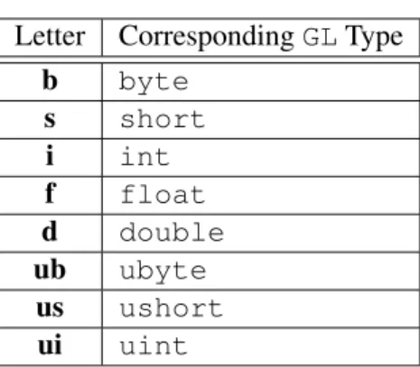
GL commands are formed from anamefollowed, depending on the particular command, by up to 4 characters. The first character indicates the number of values of the indicated type that must be presented to the command. The second character or character pair indicates the specific type of the arguments: 8-bit integer, 16-bit integer, 32-bit integer, single-precision point, or double-precision floating-point. The final character, if present, isv, indicating that the command takes a pointer to an array (a vector) of values rather than a series of individual arguments. Two specific examples are:
void Uniform4f(intlocation, floatv0, floatv1, floatv2, floatv3);
and
2.3. GL COMMAND SYNTAX 14
Letter CorrespondingGLType
b byte
s short
i int
f float
d double
ub ubyte
us ushort
ui uint
Table 2.1: Correspondence of command suffix letters to GL argument types. Refer to table2.2for definitions of the GL types.
These examples show the ANSICdeclarations for these commands. In general, a command declaration has the form1
rtypeName{1234}{b s i f d ub us ui}{v}
([args ,] T arg1 ,. . ., T argN [, args] );
rtypeis the return type of the function. The braces ({}) enclose a series of char-acters (or character pairs) of which one is selected. indicates no character. The arguments enclosed in brackets ([args ,]and[, args]) may or may not be present. TheNargumentsarg1throughargN have typeT, which corresponds to one of the type letters or letter pairs as indicated in table2.1 (if there are no letters, then the arguments’ type is given explicitly). If the final character is notv, thenN is given by the digit1,2,3, or4(if there is no digit, then the number of arguments is fixed). If the final character isv, then onlyarg1is present and it is an array ofN values of the indicated type. Finally, we indicate anunsignedtype by the shorthand of prepending auto the beginning of the type name (so that, for instance,unsigned byteis abbreviatedubyte).
For example,
void Uniform{1234}{if}(intlocation, Tvalue);
indicates the eight declarations
void Uniform1i(intlocation, intvalue); 1
2.4. BASIC GL OPERATION 15
void Uniform1f(intlocation, floatvalue); void Uniform2i(intlocation, intv0, intv1); void Uniform2f(intlocation, floatv0, floatv1); void Uniform3i(intlocation, intv0, intv1, intv2); void Uniform3f(intlocation, floatv1, floatv2,
floatv2 );
void Uniform4i(intlocation, intv0, intv1, intv2, intv3);
void Uniform4f(intlocation, floatv0, floatv1, floatv2, floatv3);
Arguments whose type is fixed (i.e. not indicated by a suffix on the command) are of one of the GL data types summarized in table2.2, or pointers to one of these types.
2.4
Basic GL Operation
Figure2.1shows a schematic diagram of the GL. Commands enter the GL on the left. Some commands specify geometric objects to be drawn while others control how the objects are handled by the various stages. Commands are effectively sent through a processing pipeline.
The first stage operates on geometric primitives described by vertices: points, line segments, and polygons. In this stage vertices may be transformed and lit, and primitives are clipped to a viewing volume in preparation for the next stage, rasterization. The rasterizer produces a series of framebuffer addresses and values using a two-dimensional description of a point, line segment, or polygon. Each
fragmentso produced is fed to the next stage that performs operations on individ-ual fragments before they finally alter the framebuffer. These operations include conditional updates into the framebuffer based on incoming and previously stored depth values (to effect depth buffering), blending of incoming fragment colors with stored colors, as well as masking and other logical operations on fragment values.
Finally, values may also be read back from the framebuffer or copied from one portion of the framebuffer to another. These transfers may include some type of decoding or encoding.
2.4. BASIC GL OPERATION 16
GL Type Minimum Description Bit Width
boolean 1 Boolean
byte 8 Signed 2’s complement binary integer
ubyte 8 Unsigned binary integer
char 8 Characters making up strings
short 16 Signed 2’s complement binary integer
ushort 16 Unsigned binary integer
int 32 Signed 2’s complement binary integer
uint 32 Unsigned binary integer
sizei 32 Non-negative binary integer size
enum 32 Enumerated binary integer value
intptr ptrbits Signed 2’s complement binary integer
sizeiptr ptrbits Non-negative binary integer size
bitfield 32 Bit field
half 16 Half-precision floating-point value encoded in an unsigned scalar
float 32 Floating-point value
clampf 32 Floating-point value clamped to[0,1]
double 64 Floating-point value
clampd 64 Floating-point value clamped to[0,1]
Table 2.2: GL data types. GL types are not C types. Thus, for example, GL type int is referred to as GLintoutside this document, and is not necessarily equivalent to the C type int. An implementation may use more bits than the number indicated in the table to represent a GL type. Correct interpretation of integer values outside the minimum range is not required, however.
2.4. BASIC GL OPERATION 17
Vertex Shading and
Per-Vertex Operations
Primitive Assembly
and Rasterization
Fragment Shading and Per-Fragment
Operations
Framebuffer
Pixel Pack/Unpack
Texture Memory Transform
Feedback
Vertex Data
Pixel Data
2.5. GL ERRORS 18
2.5
GL Errors
The GL detects only a subset of those conditions that could be considered errors. This is because in many cases error checking would adversely impact the perfor-mance of an error-free program.
The command
enum GetError(void);
is used to obtain error information. Each detectable error is assigned a numeric code. When an error is detected, a flag is set and the code is recorded. Further errors, if they occur, do not affect this recorded code. WhenGetError is called, the code is returned and the flag is cleared, so that a further error will again record its code. If a call toGetErrorreturnsNO ERROR, then there has been no detectable error since the last call toGetError(or since the GL was initialized).
To allow for distributed implementations, there may be several flag-code pairs. In this case, after a call to GetErrorreturns a value other than NO ERROR each subsequent call returns the non-zero code of a distinct flag-code pair (in unspecified order), until all non-NO ERRORcodes have been returned. When there are no more non-NO ERRORerror codes, all flags are reset. This scheme requires some positive number of pairs of a flag bit and an integer. The initial state of all flags is cleared and the initial value of all codes isNO ERROR.
Table2.3summarizes GL errors. Currently, when an error flag is set, results of GL operation are undefined only ifOUT OF MEMORYhas occurred. In other cases, the command generating the error is ignored so that it has no effect on GL state or framebuffer contents. If the generating command returns a value, it returns zero. If the generating command modifies values through a pointer argument, no change is made to these values. These error semantics apply only to GL errors, not to system errors such as memory access errors. This behavior is the current behavior; the action of the GL in the presence of errors is subject to change.
Several error generation conditions are implicit in the description of every GL command:
• If a command that requires an enumerated value is passed a symbolic con-stant that is not one of those specified as allowable for that command, the errorINVALID ENUMis generated. This is the case even if the argument is a pointer to a symbolic constant, if the value pointed to is not allowable for the given command.
• If a negative number is provided where an argument of type sizei or
2.6. PRIMITIVES AND VERTICES 19
Error Description Offending
com-mand ignored?
INVALID ENUM enumargument out of range Yes
INVALID VALUE Numeric argument out of range Yes
INVALID OPERATION Operation illegal in current state Yes
INVALID FRAMEBUFFER OPERATION Framebuffer object is not com-plete
Yes
OUT OF MEMORY Not enough memory left to
exe-cute command
Unknown
Table 2.3: Summary of GL errors
• If memory is exhausted as a side effect of the execution of a command, the errorOUT OF MEMORYmay be generated.
Otherwise, errors are generated only for conditions that are explicitly described in this specification.
2.6
Primitives and Vertices
In the GL, most geometric objects are drawn by specifying a series of generic attribute sets usingDrawArraysor one of the other drawing commands defined in section2.8.2. There are seven geometric objects that are drawn this way: points, line segment strips, line segment loops, separated line segments, triangle strips, triangle fans, and separated triangles,
Each vertex is specified with one or more generic vertex attributes. Each at-tribute is specified with one, two, three, or four scalar values. Generic vertex attributes can be accessed from within vertex shaders (section 2.11) and used to compute values for consumption by later processing stages.
The methods by which generic attributes are sent to the GL, as well as how attributes are used by vertex shaders to generate vertices mapped to the two-dimensional screen, are discussed later.
Before vertex shader execution, the state required by a vertex is its generic vertex attributes. Vertex shader execution processes vertices producing a homo-geneous vertex position and any varying outputs explicitly written by the vertex shader.
2.6. PRIMITIVES AND VERTICES 20
Point, Line Segment, or
Triangle (Primitive) Assembly
Point culling, Line Segment or Triangle
clipping
Rasterization Shaded
Vertices
Coordinates
Varying Outputs
Primitive type (from DrawArrays or DrawElements mode) Vertex
Shader Execution
Generic Vertex Attributes
2.6. PRIMITIVES AND VERTICES 21
is clipped to a viewing volume. This may alter the primitive by altering vertex coordinates and varying vertex shader outputs. In the case of line and polygon primitives, clipping may insert new vertices into the primitive. The vertices defin-ing a primitive to be rasterized have varydefin-ing outputs associated with them.
2.6.1 Primitive Types
A sequence of vertices is passed to the GL usingDrawArraysor one of the other drawing commands defined in section2.8.2. There is no limit to the number of vertices that may be specified, other than the size of the vertex arrays. Themode
parameter of these commands determines the type of primitives to be drawn using the vertices. The types, and the correspondingmodeparameters, are:
Points. A series of individual points may be specified with mode POINTS. Each vertex defines a separate point.
Line Strips.A series of one or more connected line segments may be specified withmode LINE STRIP. In this case, the first vertex specifies the first segment’s start point while the second vertex specifies the first segment’s endpoint and the second segment’s start point. In general, theith vertex (fori > 1) specifies the beginning of theith segment and the end of thei−1st. The last vertex specifies the end of the last segment. If only one vertex is specified, then no primitive is generated.
The required state consists of the processed vertex produced from the last ver-tex that was sent (so that a line segment can be generated from it to the current vertex), and a boolean flag indicating if the current vertex is the first vertex.
Line Loops. Line loops may be specified with modeLINE LOOP. Loops are the same as line strips except that a final segment is added from the final specified vertex to the first vertex. The required state consists of the processed first vertex, in addition to the state required for line strips.
Separate Lines. Individual line segments, each specified by a pair of vertices, may be specified withmodeLINES. The first two vertices passed define the first segment, with subsequent pairs of vertices each defining one more segment. If the number of specified vertices is odd, then the last one is ignored. The state required is the same as for line strips but it is used differently: a processed vertex holding the first vertex of the current segment, and a boolean flag indicating whether the current vertex is odd or even (a segment start or end).
2.6. PRIMITIVES AND VERTICES 22
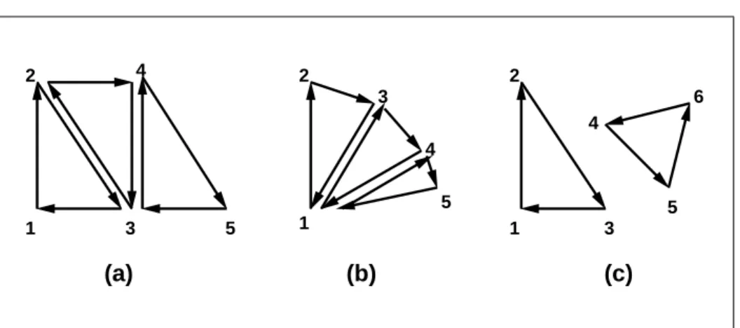
(a) (b) (c)
1 2
3 4
5 1
2
3
4
5 1 2
3 4
5 6
Figure 2.3. (a) A triangle strip. (b) A triangle fan. (c) Independent triangles. The numbers give the sequencing of the vertices in order within the vertex arrays. Note that in (a) and (b) triangle edge ordering is determined by the first triangle, while in (c) the order of each triangle’s edges is independent of the other triangles.
produced. See figure2.3.
The required state consists of a flag indicating if the first triangle has been completed, two stored processed vertices, (called vertex A and vertex B), and a one bit pointer indicating which stored vertex will be replaced with the next vertex. The pointer is initialized to point to vertex A. Each successive vertex toggles the pointer. Therefore, the first vertex is stored as vertex A, the second stored as vertex B, the third stored as vertex A, and so on. Any vertex after the second one sent forms a triangle from vertex A, vertex B, and the current vertex (in that order).
Triangle fans.A triangle fan is the same as a triangle strip with one exception: each vertex after the first always replaces vertex B of the two stored vertices. A triangle fan may be specified withmodeTRIANGLE FAN.
Separate Triangles. Separate triangles are specified with modeTRIANGLES. In this case, The3i+ 1st,3i+ 2nd, and3i+ 3rd vertices (in that order) determine a triangle for eachi= 0,1, . . . , n−1, where there are3n+kvertices drawn. kis either 0, 1, or 2; ifkis not zero, the finalkvertices are ignored. For each triangle, vertex A is vertex3iand vertex B is vertex3i+ 1. Otherwise, separate triangles are the same as a triangle strip.
Depending on the current state of the GL, apolygon primitivegenerated from a drawing command withmode TRIANGLE FAN,TRIANGLE STRIP, orTRIANGLES
2.7. VERTEX SPECIFICATION 23
rasterization and fragment shading (see sections3.6.1and3.9.2).
2.7
Vertex Specification
Vertex shaders (see section2.11) access an array of 4-component generic vertex attributes . The first slot of this array is numbered 0, and the size of the array is specified by the implementation-dependent constantMAX VERTEX ATTRIBS.
Current generic attribute values define generic attributes for a vertex when a vertex array defining that data is not enabled, as described in section2.8. The cur-rent values of a generic shader attribute declared as a floating-point scalar, vector, or matrix may be changed at any time by issuing one of the commands
void VertexAttrib{1234}{sfd}(uintindex, Tvalues); void VertexAttrib{123}{sfd}v(uintindex, Tvalues); void VertexAttrib4{bsifd ub us ui}v(uintindex, Tvalues); void VertexAttrib4Nub(uintindex, Tvalues);
void VertexAttrib4N{bsi ub us ui}v(uintindex, Tvalues);
TheVertexAttrib4N*commands specify fixed-point values that are converted to a normalized[0,1]or[−1,1]range as described in equations2.1 and2.2, re-spectively, while the other commands specify values that are converted directly to the internal floating-point representation.
The resulting value(s) are loaded into the generic attribute at slotindex, whose components are namedx, y,z, andw. TheVertexAttrib1*family of commands sets thexcoordinate to the provided single argument while settingyandzto 0 and
wto 1. Similarly,VertexAttrib2*commands setxandyto the specified values,
zto 0 andwto 1;VertexAttrib3*commands setx,y, andz, withwset to 1, and VertexAttrib4*commands set all four coordinates.
TheVertexAttrib*entry points may also be used to load shader attributes de-clared as a floating-point matrix. Each column of a matrix takes up one generic 4-component attribute slot out of theMAX VERTEX ATTRIBSavailable slots. Ma-trices are loaded into these slots in column major order. Matrix columns are loaded in increasing slot numbers.
The resulting attribute values are undefined if the base type of the shader at-tribute at slotindexis not floating-point (e.g. is signed or unsigned integer). To load current values of a generic shader attribute declared as a signed or unsigned scalar or vector, use the commands
2.8. VERTEX ARRAYS 24
void VertexAttribI4{bs ubus}v(uintindex, Tvalues);
These commands specify values that are extended to full signed or unsigned integers, then loaded into the generic attribute at slotindexin the same fashion as described above.
The resulting attribute values are undefined if the base type of the shader at-tribute at slotindexis floating-point; if the base type is integer and unsigned in-teger values are supplied (theVertexAttribI*ui, VertexAttribI*us, and Vertex-AttribI*ubcommands); or if the base type is unsigned integer and signed integer values are supplied (theVertexAttribI*i,VertexAttribI*s, andVertexAttribI*b commands)
The error INVALID VALUEis generated by VertexAttrib*if indexis greater than or equal toMAX VERTEX ATTRIBS.
The state required to support vertex specification consists of the value of
MAX VERTEX ATTRIBS four-component vectors to store generic vertex attributes. The initial values for all generic vertex attributes are(0.0,0.0,0.0,1.0).
2.8
Vertex Arrays
Vertex data is placed into arrays that are stored in the server’s address space (de-scribed in section2.9). Blocks of data in these arrays may then be used to specify multiple geometric primitives through the execution of a single GL command. The client may specify up to the value of MAX VERTEX ATTRIBSarrays to store one or more generic vertex attributes. The commands
void VertexAttribPointer(uintindex, intsize, enumtype,
booleannormalized, sizeistride, const
void*pointer);
void VertexAttribIPointer(uintindex, intsize, enumtype,
sizeistride, const void*pointer);
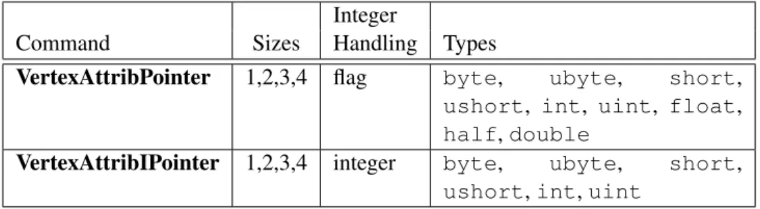
describe the locations and organizations of these arrays. For each command,type
specifies the data type of the values stored in the array. size indicates the number of values per vertex (1, 2, 3, or 4) that are stored in the array. Ta-ble 2.4indicates the allowable values forsizeandtype(when present). Fortype
the valuesBYTE,SHORT, INT, FLOAT,HALF FLOAT, and DOUBLEindicate types
byte, short, int, float, half, and double, respectively; and the values
UNSIGNED BYTE,UNSIGNED SHORT, andUNSIGNED INTindicate typesubyte,
ushort, anduint, respectively. The errorINVALID VALUEis generated ifsize
2.8. VERTEX ARRAYS 25
Integer
Command Sizes Handling Types
VertexAttribPointer 1,2,3,4 flag byte, ubyte, short,
ushort, int, uint, float,
half,double
VertexAttribIPointer 1,2,3,4 integer byte, ubyte, short,
ushort,int,uint
Table 2.4: Vertex array sizes (values per vertex) and data types. The “Integer Han-dling” column indicates how fixed-point data types are handled: “integer” means that they remain as integer values, and “flag” means that they are either converted to floating-point directly, or converted by normalizing to[0,1](for unsigned types) or[−1,1](for signed types), depending on the setting of the normalized flag in VertexAttribPointer.
The index parameter in the VertexAttribPointer and VertexAttribIPointer commands identifies the generic vertex attribute array being described. The er-rorINVALID VALUEis generated ifindexis greater than or equal to the value of
MAX VERTEX ATTRIBS. Generic attribute arrays with integertype arguments can be handled in one of three ways: converted to float by normalizing to [0,1] or
[−1,1]as described in equations2.1and2.2, respectively; converted directly to float, or left as integers. Data for an array specified byVertexAttribPointerwill be converted to floating-point by normalizing ifnormalizedisTRUE, and converted directly to floating-point otherwise. Data for an array specified by VertexAttribI-Pointer will always be left as integer values; such data are referred to as pure
integers.
The one, two, three, or four values in an array that correspond to a single vertex comprise an arrayelement. The values within each array element are stored se-quentially in memory. Ifstrideis specified as zero, then array elements are stored sequentially as well. The errorINVALID VALUEis generated ifstrideis negative. Otherwise pointers to theith and(i+ 1)st elements of an array differ bystride
basic machine units (typically unsigned bytes), the pointer to the(i+ 1)st element being greater. For each command,pointerspecifies the offset within a buffer of the first value of the first element of the array being specified.
An individual generic vertex attribute array is enabled or disabled by calling one of
2.8. VERTEX ARRAYS 26
where index identifies the generic vertex attribute array to enable or disable. The error INVALID VALUE is generated if index is greater than or equal to
MAX VERTEX ATTRIBS.
2.8.1 Transferring Array Elements
When an array elementiis transferred to the GL byDrawArrays,DrawElements, or the otherDraw*commands described below, each generic attribute is expanded to four components. Ifsizeis one then thexcomponent of the attribute is specified by the array; they,z, andwcomponents are implicitly set to 0, 0, and 1, respec-tively. Ifsizeis two then thexandycomponents of the attribute are specified by the array; thezandwcomponents are implicitly set to 0 and 1, respectively. Ifsize
is three thenx,y, andzare specified, andwis implicitly set to 1. Ifsizeis four then all components are specified.
Primitive restarting is enabled or disabled by calling one of the commands
void Enable(enumtarget);
and
void Disable(enumtarget);
withtargetPRIMITIVE RESTART. The command
void PrimitiveRestartIndex(uintindex);
specifies a vertex array element that is treated specially when primitive restarting is enabled. This value is called theprimitive restart index. When one of theDraw* commands transfers the ith successive set of generic attribute array elements to the GL, ifi2 is equal to the primitive restart index, then the GL does not process those elements as a vertex. Instead, it is as if the drawing command ended with the immediately preceding transfer, and another drawing command is immediately started with the same parameters, but only transferring elementsi+ 1through the end of the originally specified elements.
2
2.8. VERTEX ARRAYS 27
2.8.2 Drawing Commands
The command
void DrawArrays(enummode, intfirst, sizeicount);
constructs a sequence of geometric primitives by transferring elements f irst
throughf irst+count−1of each enabled array to the GL.modespecifies what kind of primitives are constructed, as defined in section2.6.1. If an array cor-responding to a generic attribute required by a vertex shader is not enabled, then the corresponding element is taken from the current generic attribute state (see section2.7).
If an array corresponding to a generic attribute required by a vertex is enabled, the corresponding current generic attribute value is undefined after the execution ofDrawArrays.
Specifying f irst < 0 results in undefined behavior. Generating the error
INVALID VALUEis recommended in this case. The command
void MultiDrawArrays(enummode, int*first, sizei*count, sizeiprimcount);
behaves identically toDrawArrays except thatprimcountseparate ranges of elements are specified instead. It has the same effect as:
for (i = 0; i < primcount; i++) {
if (count[i] > 0)
DrawArrays(mode, f irst[i], count[i]);
}
The command
void DrawElements(enummode, sizeicount, enumtype, void*indices);
constructs a sequence of geometric primitives by successively transferring the
count elements whose indices are stored in the currently bound element array buffer (see section2.9.5) at the offset defined by indices to the GL. The ith el-ement transferred by DrawElements will be taken from element indices[i] of each enabled array. typemust be one ofUNSIGNED BYTE,UNSIGNED SHORT, or
2.8. VERTEX ARRAYS 28
defined in section2.6.1. If an array corresponding to a generic attribute required by a vertex shader is not enabled, then the corresponding element is taken from the current generic attribute state (see section2.7).
If an array corresponding to a generic attribute required by a vertex is enabled, the corresponding current generic attribute value is undefined after the execution ofDrawElements.
The command
void MultiDrawElements(enummode, sizei*count, enumtype, void**indices, sizeiprimcount);
behaves identically to DrawElementsexcept thatprimcount separate lists of elements are specified instead. It has the same effect as:
for (i = 0; i < primcount; i++) {
if (count[i]) > 0)
DrawElements(mode, count[i], type, indices[i]);
}
The command
void DrawRangeElements(enummode, uintstart, uintend, sizeicount, enumtype, void*indices);
is a restricted form ofDrawElements. mode,count, type, andindices match the corresponding arguments toDrawElements, with the additional constraint that all index values identified byindicesmust lie betweenstartandendinclusive.
Implementations denote recommended maximum amounts of vertex and index data, which may be queried by callingGetIntegerv with the symbolic constants
MAX ELEMENTS VERTICESandMAX ELEMENTS INDICES. Ifend−start+ 1is greater than the value of MAX ELEMENTS VERTICES, or if count is greater than the value ofMAX ELEMENTS INDICES, then the call may operate at reduced per-formance. There is no requirement that all vertices in the range[start, end]be referenced. However, the implementation may partially process unused vertices, reducing performance from what could be achieved with an optimal index set.
2.8. VERTEX ARRAYS 29
The internal counterinstanceIDis a 32-bit integer value which may be read by a vertex shader asgl InstanceID, as described in section2.11.7. The value of this counter is always zero, except as noted below.
The command
void DrawArraysInstanced(enummode, intfirst,
sizeicount, sizeiprimcount);
behaves identically toDrawArraysexcept that primcountinstances of the range of elements are executed and the value ofinstanceIDadvances for each iteration. It has the same effect as:
if (modeorcountis invalid)
generate appropriate error
else {
for (int i = 0; i < primcount; i++) {
instanceID = i;
DrawArrays(mode, f irst, count);
}
instanceID = 0;
}
The command
void DrawElementsInstanced(enummode, sizeicount,
enumtype, const void*indices, sizeiprimcount);
behaves identically toDrawElementsexcept thatprimcountinstances of the set of elements are executed, and the value ofinstanceIDadvances for each iteration. It has the same effect as:
if (mode,count, ortypeis invalid)
generate appropriate error
else {
for (int i = 0; i < primcount; i++) {
instanceID = i;
DrawElements(mode, count, type, indices);
}
instanceID = 0;
2.9. BUFFER OBJECTS 30
If the number of supported generic vertex attributes (the value of
MAX VERTEX ATTRIBS) is n, then the client state required to implement vertex arrays consists of nboolean values, nmemory pointers, ninteger stride values,
nsymbolic constants representing array types,nintegers representing values per element,n boolean values indicating normalization, nboolean values indicating whether the attribute values are pure integers, and an unsigned integer representing the restart index.
In the initial state, the boolean values are each false, the memory pointers are eachNULL, the strides are each zero, the array types are eachFLOAT, the integers representing values per element are each four, the normalized and pure integer flags are each false, and the restart index is zero.
2.9
Buffer Objects
Vertex array data are stored in high-performance server memory. GL buffer ob-jects provide a mechanism that clients can use to allocate, initialize, and render from such memory.
The command
void GenBuffers(sizein, uint*buffers);
returns n previously unused buffer object names in buffers. These names are marked as used, for the purposes ofGenBuffersonly, but they acquire buffer state only when they are first bound withBindBuffer(see below), just as if they were unused.
Buffer objects are deleted by calling
void DeleteBuffers(sizein, const uint*buffers);
bufferscontainsnnames of buffer objects to be deleted. After a buffer object is deleted it has no contents, and its name is again unused. Unused names inbuffers
are silently ignored, as is the value zero.
A buffer object is created by binding a name returned byGenBuffers to a buffer target. The binding is effected by calling
void BindBuffer(enumtarget, uintbuffer);
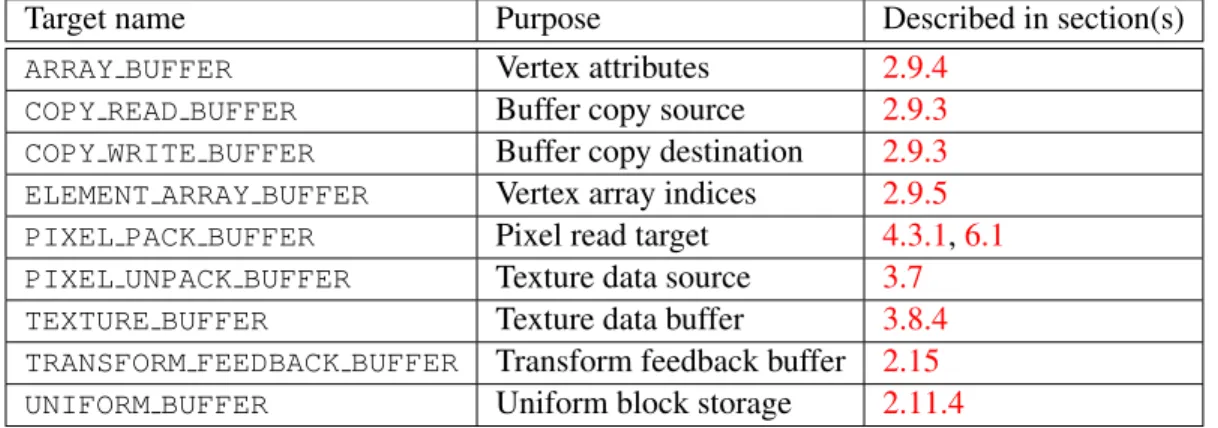
targetmust be one of the targets listed in table2.5. If the buffer object namedbuffer
2.9. BUFFER OBJECTS 31
Target name Purpose Described in section(s)
ARRAY BUFFER Vertex attributes 2.9.4
COPY READ BUFFER Buffer copy source 2.9.3
COPY WRITE BUFFER Buffer copy destination 2.9.3
ELEMENT ARRAY BUFFER Vertex array indices 2.9.5
PIXEL PACK BUFFER Pixel read target 4.3.1,6.1
PIXEL UNPACK BUFFER Texture data source 3.7
TEXTURE BUFFER Texture data buffer 3.8.4
TRANSFORM FEEDBACK BUFFER Transform feedback buffer 2.15
UNIFORM BUFFER Uniform block storage 2.11.4
Table 2.5: Buffer object binding targets.
Name Type Initial Value Legal Values
BUFFER SIZE integer 0 any non-negative integer
BUFFER USAGE enum STATIC DRAW STREAM DRAW,STREAM READ,
STREAM COPY,STATIC DRAW,
STATIC READ,STATIC COPY,
DYNAMIC DRAW,DYNAMIC READ,
DYNAMIC COPY
BUFFER ACCESS enum READ WRITE READ ONLY,WRITE ONLY,
READ WRITE
BUFFER ACCESS FLAGS integer 0 See section2.9.1
BUFFER MAPPED boolean FALSE TRUE,FALSE
BUFFER MAP POINTER void* NULL address
BUFFER MAP OFFSET integer 0 any non-negative integer
BUFFER MAP LENGTH integer 0 any non-negative integer