Co-ordinate Control for Fuel Cell And Photovoltaic Cell
Gurram Nookaraju , S.Gangadharan , B.SubbareddyM.Tech Scholar, Assistant Professor, HOD, Department of EEE Kakinada Institute of Technology And Sciences (Kits), Divili
ABSTRACT
The usual natural fuel energy resources such as petroleum, natural gas, and coal are getting shortage rapidly by fulfilling the high demand of the energy sector in the world. Also, affect the environment and leads to the greenhouse effect and serious pollution problem. Therefore renewable energy sources like solar, wind, tidal etc. are gaining more attention as an alternative energy.
The hierarchical structure of the convention power system is experiencing a paradigm shift into a deregulated system. As a result many small generators are been connected to the system at the distribution level. In order to supply a reliable and sustainable power to select customers it becomes mandatory to connect renewable and dispatchable sources. This would result in a hybrid system which can operate in autonomous or non-autonomous mode. This project aims at analysing the performance of one such autonomous system for varying demand. PV and fuel cell sources are considered to form the hybrid system under concern.
An overall coordinated controller has been analysed to ensure power sharing among the different sources used in the hybrid system also incorporating variations in the solar irradiations. Also a simulation for generation of pulses for appropriate switching of control between the different sources through MATLAB has been attempted in this work.
1.1 INTRODUCTION
The conventional fossil fuel energy sources such as petroleum, natural gas, and coal which meet most of the world’s energy demand today are getting depleted rapidly. Also, their by-products affect our environment due to the greenhouse effect and pollution problem. The renewable energy sources (solar, wind, tidal etc.) are gaining more importance as an alternative energy. Among the renewable energy sources, the Photovoltaic
(PV) has been widely utilized in low power applications. It is one of the most promising
scale users as the fabrication of low cost PV devices becomes a reality.
Photovoltaic generators which directly convert solar radiation into electricity have a lot of significant advantages such as being inexhaustible. Due to harmless environmental effect of PV generators, they are replacing electricity generation by other polluting ways and even more popular.
In many regions of the world, the fluctuating nature of solar radiation means that purely PV power generators for off grid applications must be large and thus expensive. One method to overcome this problem is to integrate the photovoltaic plant with other power sources such as diesel, fuel cell (FC), or battery back-up.
The fuel cell back-up power supply is a very attractive option to be used with an intermittent power generation source like PV because the fuel cell generator is characterized with many attractive features such as efficiency, fast load-response, modular production and fuel flexibility. Its feasibility in co-ordination with a PV system has been successfully realized for both grid-connected and standard-alone power applications. Due to the fast responding capability of the fuel cell power system, a photovoltaic-fuel cell (PVFC) hybrid system may be able to solve the photovoltaic inherent problem of intermittent power generation.
Environmental impacts of the fuel cell power generation are relatively less when compared to other fossil fuel based power sources. Since chemical reactions inside the fuel cell stack are accomplished by a catalyst, it requires a low sulphur-content fuel. Low emission characteristics of the fuel generator may allow some utilities to offset the costs of installing additional emission control equipment. Moreover, their high efficiency results in low CO2
emission, which helps in reducing the rate of global warming. Therefore, the fuel cell generator has a great potential for being co-ordinated with the PV generator to smooth out the photovoltaic power fluctuations.
energy or distributed energy generates electricity from many small energy sources. Currently, industrial countries generate most of their electricity in large centralized facilities, such as fossil fuel (coal, gas powder) nuclear or hydropower plants. These plants have excellent economies of scale, but usually transmit electricity long distances and negatively affect the environment.
Most plants are built this way due to a number of economic, health and safety, logistical, environmental, geographical and geological factors. For example, coal power plants are built away from cities to prevent their heavy air pollution from affecting the populace. In addition, such plants are often built near collieries to minimize the cost of transporting coal.
Now-a-days, new advances in technology and new directions in electricity regulation encourage a significant increase of distributed generation resources around the world. The currently competitive small generation units and the incentive laws of use renewable energies force electric utility companies to construct an increasing number of distributed energy systems (DES) on its distribution network, instead of large central power plants. Moreover, distribution energy systems can improve service reliability, better economics. DES has mainly been used as a standby power source for critical businesses.
Fuel cells are also well used for distributed generation application, and can essentially be described as batteries which never become discharged as long as hydrogen and oxygen are continuously provides. The hydrogen can be supplied directly, or produced from natural gas, or liquid fuels.
HYBRID POWER GENERATION SYSTEM
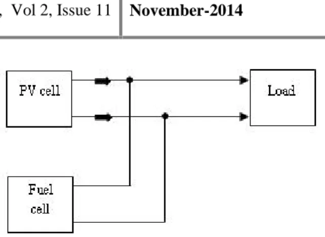
Hybrid power generation systems are designed generally independent of large centralized electric grids and are used in remote areas. Hybrid systems by definition contain a number of power generation sources such as wind turbines, photovoltaic, micro-hydro and fossil fuel based generators. Hybrid power systems range from small systems designed for one or several homes to very large ones for remote island grids or large communities’ [1].
block diagram of simple hybrid power system
PV cell modelling
Fig 2.3 shows the equivalent circuit of PV cell
Fig.2.3 Equivalent circuit of PV cell
With reference to equivalent circuit, the PV panel current IPVis expressed as:
= − −
(2.2)
= − ( ) − 1 −
(2.3)
Assuming ( ) − 1 ≫ 1
= 10 =
Now equation (2.2) is written as[8]
= −
Where = 10 . ( + )
(2.4)
From the equation (2.3), the value of VOC is
expressed as = (2.5)
Here VPV,IPV= Output voltage and current of the PV
panel
ISC= Photocurrent (A)
I0= Saturation current (A)
q = Electron charge in coulombs
T = Junction temperature in Kelvin and n = Ideality factor
Implementations
This chapter deals with two types of controllers viz., Maximum Power Point Tracking controller for PV system and an overall coordinated controller for the hybrid system. Also a program in Modelsim software has been developed in view of generating pulses for MPPT controller and overall coordinated controller.
MAXIMUM POWER POINT TRACKING
CONTROLLER
The efficiency of a solar cell is very low. In order to increase the efficiency, methods are to be undertaken to match the source and load properly. One such method is the Maximum Power Point Tracking (MPPT). This is a technique used to obtain the maximum possible power from a varying source. In photovoltaic systems the I-V curve is non-linear, thereby making it difficult to be used to power a certain load. This is done by utilizing a boost converter whose duty cycle is varied by using a MMPT algorithm. The boost converter is used on the load side and solar panels are used to power this converter [9].
3.2.1 Perturbation and Observation (P & O) algorithm
Perturbation and Observation (P&O) method has a simple feedback structure and fewer measured parameters. It operates by periodically perturbing (i.e. incrementing or decreasing) the PV terminal voltage and comparing the PV output power with that of the previous perturbation cycle. If the perturbation leads to an increase (decrease) in array power, the subsequent perturbation is made in the same (opposite) direction. In this manner, the peak power tracker continuously seeks the peak power condition. .The voltage and current from PV array are sensed instantaneously and hence instantaneous power is calculated. Accordingly, the duty ratio is adjusted and drives the boost converter to deliver the maximum power output [9].
Figure 3.1 shows the flow chart of algorithm used in MPPT controller for boost converter. d+k and d-k represent the subsequent perturbation in the same or opposite direction, respectively.
Fig. 3.1 Flow chart of the P & O algorithm
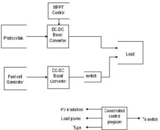
Overall coordinated controller
Fig. 3.2 shows the coordinated control for hybrid power system. This controller compares the possible power to be generated from PV with the load and accordingly decides the instant of switching ON the dispatchable source and also the magnitude power to be extracted from the fuel cell is decided. This procedure is shown as flow chart in fig.3.3.
Fig. 3.2 Block diagram of overall coordinated controller
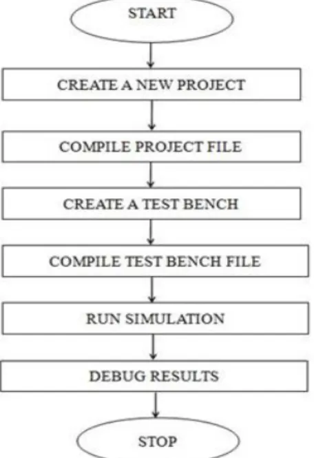
ModelSim is a verification and simulation tool for VHDL, Verilog, SystemVerilog, and mixed-language designs. The basic steps for simulating a step by step procedure in ModelSim is shown as flow chart in fig.3.5.
Fig 3.5 Algorithm for simulating results in MODELSIM
Result and discussion
Table 4.1 configuration parameters of the photovoltaic system
Simulation results:
The variation in the maximum power generated by the PV source tabulated in table 4.3 is graphically shown in fig 4.2. this shows that the MPPT controller tracks maximum power point corresponding to every change in the irradiation. PV system consist three cells in series connected in a stack and such four stacks are connected in parallel to increase the current rating.
Fig. 4.2 PV with MPPT output power
In fig. 4.6 clk_in = 10 MHz, initial voltage = 16 V, initial current = 16 Amps
CONCLUSIONS AND FUTURE SCOPE
Distributed generation is becoming an interesting alternative in view of bridging the gap between the demand and generation. In order to achieve continuous power supply to select customers it is important to concentrate on design of the distributed generation units such that both renewable and dispatchable sources are used to form a hybrid system. The performance of one such hybrid system is analysed in this project.
Since the system demand as well as the availability of the renewable energy resource vary continuously it is inevitable to operate a hybrid system with an appropriate coordinated control. Hence an attempt has been made in this project to analyse the performance of one such overall coordinated controller. It is found that the proposed controller enhances the decision making on a coordinated operation of PV and FC based DGs to feed a varying demand.
A simulation for generation of pulses in view of implementating the proposed controller through FPGA has also been attempted in this work.
Hardware implementation of the simulation work proposed in this project can be attempted as an extension of the project.
REFERENCES
[1] S.G.Tesfahunegn, P.J.S. Vie, Tore M. Undeland, “A Combined Steady State and Dynamic Model of a Proton Exchange Membrane Fuel Cell for use in DG system Simulation,” The 2010 International Power Electronics Conference
[2] H.HabeebullahSait, S.Arul Daniel, “New control paradigm for integration of photovoltaic energy sourceswith utility network,” Electrical Power and
Energy Systems journal 33 (2011) 86–93.
[3] S.Pasricha and S.R.Shaw, “A dynamic PEM fuel cell model,” IEEE Trans. Energy Convers., Vol.21,
No.2, pp 484–490, Jun.2006.
[4] Sukumarkamalasadan,“Modeling and Simulation of PEM Fuel Cell as a Micro grid,”IEEE Trans. Power systems, Vol.19, issue 4, pp 2022-2028, November 2004.
[5] Sachin V. Puranik, Ali Keyhani and FarshadKhorrami, “State-Space Modeling of Proton Exchange Membrane Fuel Cell,”IEEE Transactions
on energyconversion, Vol. 25, No. 3, September 2010.
[6] C.Wang, M.H.Nehrir, “Control of PEM Fuel cell Distributed generation systems”, IEEE Transactions on Energy conversion, Vol.21, No.2, June 2006
[7] W.Friede, S.Rael, and B.Davat, “Mathematical model and characterization of the transient behaviour of a PEM fuel cell,” IEEE Trans.Power Electron.,
Vol.19, No.5, PP.1234–1241, Sep.2004.
[8] J. Kim, S. Lee, S. Srinivasan, C.E. Chamberlin, “Modeling of Proton Exchange Membrane Fuel Cell Performance with an Empirical Equation,”Journal of Electrochemical Society, Vol. 142 No. 8, August 1995, PP. 2670-2674.
[10] EG&G Services, Inc., Science Applications International Corporation, “Fuel Cell Handbook
(Sixth Edition),” Office of Fossil Energy, National Energy Technology Lab, Nov. 2002.
[11] Wei Wu, Che-ChuanPai, “Modeling and Control of a Proton Exchange Membrane Fuel Cell System with Alternative Fuel Sources,”Ind. Eng. Chem. Res.
2009, 48, 8999–9005.