www.ijseat.com
Page 223
Combustion Analysis on HCCI Engine By Using Blended Fuel With
Varying Injection Timing Of PCCI
1
M.V.Raghavendra Rao
2M.Rajesh
3K.Naga Vishnu
1Associate Professor, DVR&Dr.HS MIC College Of Technology 2,3 Assistant Professor, M.V.R.College Of Engineering And Technology
123
Department of Mechanical Engineering
Abstract: There are two sorts of inside burning motors in particular the sparkle ignition (SI) and the pressure ignition (CI). Petrol and diesel are at present rule powers for SI and CI motors. These energizes are very nearly getting wiped out. The fuel oxidation process in the motor produces valuable force, as well as a lot of poison outflows including carbon dioxide (CO2), carbon monoxide (CO), unburned hydrocarbon (HC), nitrogen oxides (NOx), and particulate matter (PM).
HCCI (Homogeneous Charge Compression Ignition) is a clean and efficient combustion process. In this project work an attempt is made to experimentally analyze the combustion characteristics of the HCCI compression process in a PCCI (Premixed Charge Compression Ignition) mode assisted with pilot injection (PI). Pilot Injector is an injector which is placed at inlet manifold. Here we used B30 (700 ml of diesel+ 300 ml of bio diesel) as a secondary fuel and diesel as primary fuel. By changing the injection timing of the PCCI mode at 20o,40o,60o of the crank angle we have done an experiment and analyzed exhaust gases compared to conventional CI engine and also seen efficiencies of both HCCI and CI engines
1. INTRODUCTION
In today’s world, the Internal Combustion (IC) engine is the key to the entire transportation sector. Without the transportation performed by the millions of vehicles on road and at sea, we would not have reached modern living standards. The Spark Ignition (SI) and the Compression Ignition (CI) are the two sorts of IC motors. Petrol and diesel are at present the key powers utilized for SI and CI motors individually. These energizes are nearly getting terminated and amid burning these fills discharge a generous measure of poisons into the air and make environment related issues. The IC engine is known as one of the major
sources of air pollutants in the environment. The fuel oxidation process in the motor produces valuable force, as well as a lot of poison emanations including Carbon Dioxide (CO2), Carbon Monoxide (CO), Unburned Hydrocarbon (HC), Nitrogen Oxides (NOx), and Particulate Matter (PM). Diminishing the fumes emanations and expanding the mileage of IC motors are of worldwide significance.
www.ijseat.com
Page 224
2. EXPRIMENTAL SETUP
2.1 Introduction
The engine experiments are conducted to validate the application of the analysis and to implement strategies for HCCI start ability and control. In the present research work, an agricultural water-cooled single cylinder engine which is very well-suited for HCCI operation has been used. Experiments are conducted for different load conditions and different fuel combinations. Based on the results obtained from the experiments, the performance and emission graphs are plotted. The detailed description of the experimental setup, properties of the samples and experimental procedures are discussed in this chapter.
2.2 Experimental Apparatus
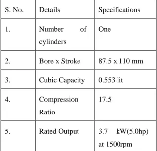
The research engine was based on a single cylinder, Direct Injection (DI), and four-stroke cycle diesel engine with 0.553 lit of piston displacement (agricultural type water-cooled). The specifications and dimensions of the test engine are listed in Table 2.1. The experimental apparatus consists of the primary fuel supply system, the exhaust gas analyzer system, the thermostat air temperature control system and the pilot injection system. A gravity feed fuel system with an efficient paper element filter, and force feed lubrication is also used. Large end bearings and camshaft bush, suitable for run-through or thermosyphon cooling are also provided in the present system.
Table 2.1 Specifications of the experimental setup
S. No. Details Specifications
1. Number of
cylinders
One
2. Bore x Stroke 87.5 x 110 mm
3. Cubic Capacity 0.553 lit
4. Compression
Ratio
17.5
5. Rated Output 3.7 kW(5.0hp)
at 1500rpm
6. SFC at rated
hp/1500rpm
245 g/kWh (180
g/bhp-hr)
7. Lube Oil
consumption
1.0 % of SFC
max.
8. Lube Oil Sump
Capacity
3.3 lit
9. Fuel Tank
Capacity
6.5 lit
10. Engine Weight
(dry) without
flywheel
114 kg
11. Weight of
flywheel
33 kg
12. Rotation while
looking at
flywheel
Clock-wise
13. Power take-off Flywheel end
Figure 2.1 shows the schematic diagram of the experimental apparatus used for the present research work. The pilot injection system is attached to the air manifold to supply the secondary fuel in the HCCI mode. The pilot injection system consists of a pilot injection valve and fuel measurement system. The heating and thermostat arrangements are also attached to the air manifold to preheat and measure the temperature of the air respectively. Diesel, petrol and bio diesel are used as fuels in this research work.
2.3 SAMPLE FUELS
Diesel, petrol and bio diesel are used for this research work as sample fuels. The specifications of these samples are identified by standard test methods. The properties of diesel, petrol and bio-diesel are listed in Table 2.2.
www.ijseat.com
Page 225
Properties Diesel
Density 15 0C Kg/m3 830
Octane Number -
Cetane Number 51
Kinematic Viscosity at 40°C (m2/s) 1.3
Flash point °C 55
Specific gravity 0.85
Auto-ignition Temperature (°C) 263
Molecular Weight 200
2.4 EXPERIMENTAL PROCEDURE
In this research work, experiments are conducted in the conventional and HCCI mode with all the fuel samples. Initially, the engine is operated in the conventional mode using diesel and bio-diesel as a primary fuel; there is no secondary fuel supply. The efficiency, fuel consumption, exhaust gas temperature and emissions are measured under different load conditions. The different percentages of varying loads are: 0%, 25%, 50%, 75% and 100%.
In the HCCI mode, the pilot injector is used to supply secondary fuel to the combustion chamber to get the Premixed Charged Combustion Ignition (PCCI).The pilot injector works by means of the signal from the rocker ram. The opening and closing of the pilot injector for supplying the secondary fuel depends upon the position of the rocker arm, which depends upon the position of the piston inside the combustion chamber. The air is heated to a temperature of 80°C before it is sent into the combustion chamber. The primary fuel is supplied to the combustion chamber without heating. In the case of the secondary fuel supply, the fuel is heated before entering the inlet manifold. The heating is done by an electrical heating arrangement. The secondary fuel is supplied into the combustion chamber in the suction stroke. This will create PCCI during the compression stroke and help to ignite the fuel which is supplied by primary injection and get the HCCI. This HCCI helps to get
complete combustion and uniform low temperature throughout the combustion chamber.
The exhaust gas is analyzed by means of a five-gas analyzer to measure the HC, CO, CO2, NOx and O2 present in the exhaust gas. The exhaust gas temperature and smoke contents are measured by means of the thermocouple and smoke meter respectively. The primary fuel, secondary fuel, and air quantity are measured before they enter the combustion chamber.
2.4.1 DIESEL AND B30 PCCI-DI Combustion
In this mode of experiment, both diesel and B30 (700ml diesel +300 ml biodiesel) are used as primary and secondary fuel respectively. The diesel is injected into the cylinder through the primary injector; the injected diesel is compressed to increase the pressure. The pilot injector supplied the B30 to the combustion chamber before the actual injection of the diesel into the combustion chamber through the primary injection port. The emissions and fuel consumptions are measured in this mode.The experiment is conducted at different injection timings of pilot injector i.e.,at 20o,40o,60o of the crank angle.
2.5 EXHAUST GAS ANALYSER
www.ijseat.com
Page 226
Figure .Photographic view of the exhaust gasanalyzer showing asample result
3. RESULTS AND DISCUSSION
3.1 INTRODUCTION
Several experiments have been conducted on the present experimental setup in order to assess the performance of the developed HCCI system. The effects of the load on parameters such as exhaust gas temperature, hydro carbon in exhaust, NOX emission in exhaust gas, specific fuel
consumption, brake thermal efficiency, carbon dioxide, and carbon monoxide emission are discussed in this chapter. A detailed description of the graphs comparing: the conventional and HCCI methods, hydrocarbon emissions in the conventional and HCCI methods, hydrocarbon emissions from different injection timings in the HCCI mode, NOX emissions
in the conventional and HCCI methods, NOX
emissions from different injection timings in the HCCI mode, NOX emissions with different loads in
different HCCI modes, specific fuel consumption between the conventional and HCCI methods, specific fuel consumption between different injection timings in the HCCI mode, specific fuel consumption with different loads in different HCCI modes, brake thermal efficiency between the conventional and HCCI methods, brake thermal efficiency with different injection timings in HCCI modes, brake thermal efficiency with different load in different HCCI modes,CO2 emission in the conventional and
HCCI methods,CO2 emission between different
injection timings in the HCCI mode, CO2 emissions
with different load in different HCCI modes, CO emission in the conventional and HCCI methods, CO emission between different injection timings in the HCCI mode, CO emissions with different load in different HCCI modes
3.2 EFFECT OF LOAD ON
HYDRO CARBON IN EXHAUST G A S
The hydrocarbon emission from all the modes is observed with different load conditions. Figure 3.5 represents the variation of HC emission with the increase of load from 0% to 100%. The study found that the HC emissions from the conventional diesel mode is higher than that the injection timing at 600 of the crank angle and at 200 injection timing HC emission increase at full load and at 400 injection timing, HC emission increase at no load conditions and decrease at remaining loads. The
HC emission increased with the increase of load for conventional mode and decreased with the increase the load of HCCI methods.
Fig.3.1
Variation of different loads with different HC emissions
LOAD DIESEL 200 400 600
0 54 31 61 43
25 56 31 48 46
50 52 47 48 26
75 55 43 33 16
100 58 66 55 37
Table.3.1
3.3 EFFECT OF LOAD ON NOX EMISSIONS IN
EXHAUST GAS
The effect of load on the NOX emission in
the conventional and HCCI modes. The study found that NOX emission from diesel in the conventional
engine is lower than the different injection timings of the HCCI engine at 0 to 100 % load conditions.
0 10 20 30 40 50 60 70
0 25 50 75 100
H
C
(ppm
)
Load (%)
Load vs HC
HC (diesel)
HC (20 deg)
HC (40 deg)
www.ijseat.com
Page 227
Fig.3.2
Variation of different loads with different NOX
emissions
LOAD DIESEL 200 400 600
0 165 155 180 197
25 311 265 276 345
50 709 611 653 712
75 1059 1047 1062 1083
100 1296 1086 1164 1127
Table.3.2
3.4 EFFECT OF LOAD ON
CARBONMONOXIDE
The effect of load on the CO emission in the conventional and HCCI modes. The study found that CO emission from diesel in the conventional engine is lower than the different injection timings of the HCCI engine at 0 to 100 % load conditions.
Fig.3.3
Variation of different loads with different CO emissions
LOAD DIESEL 200 400 600
0 0.09 0.09 0.19 0.14
25 0.09 0.14 0.23 0.16
50 0.07 0.2 0.13 0.08
75 0.05 0.08 0.06 0.06
100 0.05 0.31 0.25 0.26
Table.3.3
3.5 EFFECT OF LOAD ON CARBONDIOXIDE
The effect of load on the CO2 emission in the
conventional and HCCI modes. The study found that CO2 emission from diesel in the conventional engine is
lower than the different injection timings of the HCCI engine at 0 to 100 % load.
0 200 400 600 800 1000 1200 1400
0 50 100 150
NO
X
(p
p
m
)
Load%
Load vs NO
XNox(diesel) Nox(20 deg) Nox(40 deg) Nox(60deg)
0 0.05 0.1 0.15 0.2 0.25 0.3 0.35
0 25 50 75 100
C
O
(%
)
Load (%) Load vs CO
CO (diesel)
CO (20 deg)
CO (40 deg)
www.ijseat.com
Page 228
Fig.3.4
Variation of different loads with different
CO2 emissions
LOAD DIESEL 200 400 600
0 2.2 2.6 2.5 2.2
25 3.2 3.9 3.7 3.7
50 4.5 5.8 5.4 5.4
75 6.2 7.3 7.3 6.9
100 8.5 9.4 9.4 9.20
Table.3.4 4.CONCLUSION
4.1 FINDINGS FROM THE RESEARCH
The research has been
comprehensive keeping in mind the current and future needs of HCCI. The result of this exhaustive research has brought out the application of bio-diesel to the emerging needs of HCCI combustion. The salient details of the research findings are as follows:
1.
Four different modes such as the diesel and B30 PCCI-DI Combustion incorporated in the proposed HCCI system.2.
Various parameters such as exhaust gas temperature, HC, NOx , CO, SFC, BTE, and CO2 are measured and analyzed.3.
A MRU DELTA 1600L five gas analyzer is used for conducting the experiment.4. The PCCI approach is adopted to conduct the HCCI experiment.
5. The pilot Injection(PI) system is used.
4.2 LIMITATIONS
Research and development in this area is
cumbersome and takes a lot of time and large-scale effort. The limitations of the present study are that only three combinations modes are tried. Another limitation of this study is that friction losses and charge leakage through the cylinder-piston gap are not considered; it may constrain the engine size, and impose minimum engine speed limits.
4.3 SCOPE FOR FUTURE RESEARCH The present investigation has greatly expanded our understanding of HCCI, the controlling mechanisms, and HCCI engine operation strategies. However, the present research can be extended to various other alternative fuels such as CNG, LPG, biogas, and chemfuels, and the reduction of emission can be studied and analyzed. The present system can be slightly modified to design low NOx, low particulate reciprocating engines with improved diesel efficiency. Research and development is needed to develop methods to slow the rate of combustion in HCCI engines at high engine loads, to prevent excessive noise and engine damage. Similar research can also be done to develop concepts to overcome the challenge of ignition in cold HCCI engines without compromising the warm engine performance. The present system can be adopted to develop intake and exhaust manifold designs for multi-cylinder engines to overcome the challenge of maintaining strict uniformity of the inlet and exhaust flows of each cylinder to assure smooth engine operation.
4.4 CONCLUSION
This research work aims to reduce emission in HCCI engines in the PCCI mode with different injection timings. The following conclusions are drawn:
The study found that the HC emissions are decreases in HCCI modes when compared with conventional engine.
At HCCI engine 200 injection timing HC emissions are decreases than conventional mode except at full load condition.
At HCCI engine 400 injection timing HC emissions are decreases than conventional mode except at zero load condition.
At HCCI engine 200 injection timing HC emissions are decreases than conventional mode except at all loads.
0 1 2 3 4 5 6 7 8 9 10
0 25 50 75 100
CO
2
(%)
Load (%)
Load vs CO
2CO2 (diesel)
CO2 (20 deg)
CO2 (40 deg)
www.ijseat.com
Page 229
The study found that the specific fuel consumption decreased with the increase in load for all modes of operations. The lowest specific fuel consumption is observed blend as primary fuel and diesel as secondary fuel in HCCI mode at 600injection timing except at full load than conventional engine.
The study found that the Brake thermal efficiency increases in HCCI mode at 200,400,600 injection timing than conventional mode except at full load.
The study observed that the CO2 emission from
the HCCI mode is higher than conventional mode. Among all injection timings i.e., 200,400,600 in HCCI mode. We get lower CO2
emissions at 200 injection time.
The study observed that the mechanical efficiency is higher in HCCI mode compared to conventional engine.
The study found that the NOX emissions
increases with the increase in load for both conventional engine and HCCI engine at 200,400,600 injection timings. But in the case of HCCI engine at 200,400,600 injection timings NOX decreases than the conventional engine at
full load condition.
NOx,HC emissions are decreased in HCCI mode compared to conventional engine.
Specific fuel consumption also
decreases in HCCI engine when compared to conventional engine. Brake thermal efficiency is increased in
HCCI mode compared to conventional engine except at full load.
Mechanical efficiency is increased in HCCI mode compared to conventional engine.
Once properly introduced in the process, the proposed HCCI combustion system should improve performance and reduce the emission and consequently contribute to the efficiency profitability of the automobile industry.
REFERENCES
[1] Ishibashi Y. and Asai M. (1998) ‘A Low Pressure Pneumatic Direct Injection Two-Stroke Engine by Activated Radical Combustion Concept’, SAE Paper 980757.
[2] Thring R.H. (1989) ‘Homogeneous Charge Compression Ignition (HCCI) Engines’, SAE Paper 892068.
[3] Stanglmaier R.H., Ryan T.W. and Souder J.S. (2001) ‘HCCI Operation of a Dual-Fuel Natural Gas Engine for Improved Fuel Efficiency and Ultra-Low NOx Emissions at Low and Moderate Loads’, SAE Paper 2001-01-1897.
[4] Christensen M., Johansson B. and Einewall P. (1997a) ‘NOx emissions in HCCI operation depend on the fuel characteristic’, SAE Tech Pap Ser No 972824.
[5] Christensen M., Johansson B. and Einewall P. (1997) ‘Homogeneous Charge Compression Ignition (HCCI) Using Isooctane, Ethanol, and Natural Gas – A Comparison with Spark Ignition Operation’, SAE Paper 972872.
[6] Dae Sik Kim (2006) ‘Partial HCCI (homogeneous charge compression ignition) combustion as a control mechanism for HCCI combustion’, Fuel, Vol. 85, pp. 695-704.
[7] Lei Shi, Yi Cui, Kangyao Deng, Haiyong Peng and Yuanyuan Chen (2006) ‘Study of low emission homogeneous charge compression ignition (HCCI) engine using combined internal and external exhaust gas recirculation (EGR)’, Energy, Vol. 31, pp. 2665-2676.
[8] Dae Sik Kim (2007) ‘Combustion and emission characteristics of a partial homogeneous charge compression ignition engine when using two-stage injection’, Combustion Science and Technology, Vol. 179, pp. 531-551.
[9] Francisco Payri (2009) ‘Studied the amount of
each hydrocarbon species’, Atmospheric
Environmental, Vol. 43, pp. 1273-1279.