Design And Analysis Of Combined Extrusion Forging Die Behavior Under
Thermal Structural Loads
1Yedla Veerababu.2*P. Satish Reddy, N.Guru Murthy,3M Manoj4
PG Scholar, Assoc. Professor , Asst Professor, Asst Professor
Dept of Mechanical Engineering, Prasiddha College of Engg & Tech, Anathavaram [email protected],[email protected],[email protected],[email protected]
ABSTRACT
We all know extrusion and forging are two different processes of manufacturing but in recent past researches combined these two process to reduce the production time, production cost etc.Combined extrusion-forging processes are now getting importance for its abilities to give improved material properties, high production rate and less material waste when compared with that produced by machining, casting or by assembling the individual parts produced by different manufacturing processes. In its simplest form of combined extrusion forging process, a billet is forged by punch and dies with punch/die or both containing an opening for extrusion. This tooling arrangement permits the simultaneous lateral spread due to forging, and backward/forward extrusion or both forward and backward extrusion simultaneously through the die/punch opening(s).
In this study we are going to develop a die for extrusion-forging using knowledge from previous journals and books, we will develop a die for a flange with pipe using CAD and CAE packages. A basic die is designed and tested at maximum working conditions under thermal structural loads in simulation software ANSYS and the design of the die is further improvised to minimize the stress and improve life based on safety factor issues.
Key words: Combined Extrusion-Forging, Catia,
Ansys,Heat Flux,Total Deformation etc
I.INTRODUCTION
Metal forming is one of the oldest materials processing techniques which are still playing an important role in the modem life. In metal forming, as in any other manufacturing processes, the ultimate goal is to produce components of a selected material with a required geometrical shape and a structure optimized for the proposed service environment. Of the above, production of the desired shape is a major part of the manufacturing process.
forcing it through a narrow path called extrusion die and obtaining a desired shape at the end of the billet or at other locations by filling the forging die cavity. A variety of regular/irregular cross-sections and complex shape can be achieved by this process. This process has a definite advantage over other production processes used to manufacture complicated sections having re-entrant corners. Large reduction achieved even at high strain rates has made this process is one of the fastest growing metals working methods. In combined forward-backward extrusion forging process, the billet is reshaped and changed into certain shape (triangular, square, pentagon, hexagon, gear, box spanner, male female adopter) by forcing it through a narrow extrusion-forging die set up.
In this combined forward extrusion-forging process, the entire process can be divided into three stages, In the first stage, extrusion and upsetting take place simultaneously until the deformed material begins to make contact with the die wall. In the second stage, extrusion and forging takes place simultaneously until filling of the forging die cavity. In this stage, the flow of metal is restricted by the boundary wall of the forging die. In the last stage, the deformation in the head part is completed, and only steady state extrusion takes place, that the last stage of the process requires maximum load and a steady state extrusion of product taken place. This steady state maximum load is very much important for die design. The present theoretical analysis focus on this last stage steady state extrusion of the round pipe from shaped billet that already filled the forging die cavity. DIE
kick the bucket is a metal piece that is utilized for framing materials like sheet metal and plastic. For the vacuum framing of plastic sheet just a solitary shape is utilized, commonly to frame straightforward plastic compartments (called rankle packs) for stock. Vacuum shaping is viewed as a straightforward embellishment thermo framing process however utilizes an indistinguishable standards from bite the dust shaping. For the framing of sheet metal, for example, vehicle body parts, two sections might be utilized: one, called the punch, plays out the extending, bowing, as well as blanking operation, while another part, called the bite the dust square, safely clasps the work piece and gives comparable extending, bowing, and additionally blanking operation. The work piece may go through a few phases utilizing diverse instruments or operations to get the last frame. On account of a car segment there will for the most part be a shearing operation after the primary framing is done and after that extra pleating or moving operations to guarantee that every sharp edge are covered up and to add inflexibility to the board.
II. DESIGN OF DIE
Fig-1: Geometry of extrusion forging die
Fig-2: Geometry of extrusion forging die setup
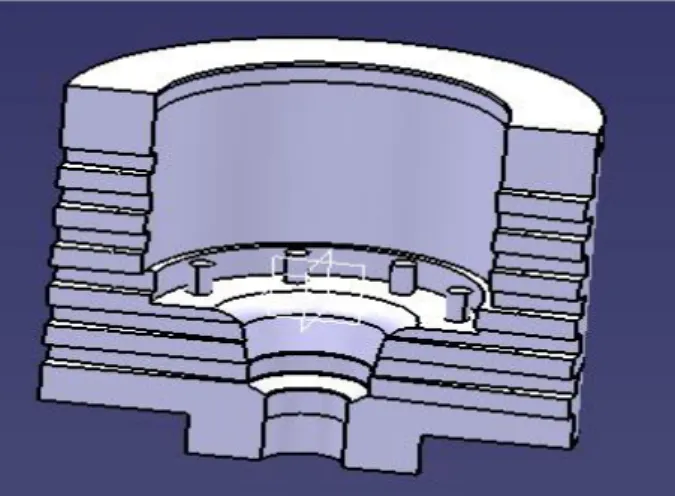
Fig -3: Cut-section of extrusion forging die
III. THERMAL ANALYSIS OF EXTRUSION FORGING DIE
Fig-4: Applying boundary conditions for Steady state Thermal analysis on model-I, H11 Hot work tool steel
Fig-6: Steady state thermal analysis (Total Heat Flux) on model-I
IV. STRUCTURAL ANALYSIS OF EXTRUSION FORGING DIE
Fig-7: Applying boundary conditions for static structural on model-I, H11 Hot work tool steel
Fig-9: Static structural analysis Equivalent (von-mises) stress on model-I
V. RESULTS AND DISCUSSIONS
STEADY STATE THERMAL ANALYSIS OF EXTRUSION FORGING DIE ALL 8 MODELS
AISI Type H11 Hot
Work Tool Steel,
Temperature ( °C) Total Heat Flux (W/mm²)
Min Max Min Max model 1 154.38 1126.9 1.20E-14 1.9608 model 2 75.387 1155.7 7.23E-16 2.5631 model 3 124.63 1146.4 7.23E-16 2.8388 model 4 61.657 1148.6 7.23E-16 2.9503 model 5 109.34 1146.1 3.49E-16 2.8136 model 6 99.388 1132 9.04E-16 2.7724 model 7 99.268 1132.4 8.89E-16 3.1437 model 8 73.562 1146.2 6.15E-16 3.2638
STATIC STRUCTURAL ANALYSIS OF EXTRUSION FORGING DIE ALL 8 MODELS
AISI Typ
e H11
Hot Wor k Tool
Total Deformati
on (mm)
Equivalent Elastic
Strain (mm/mm)
Equivalent (von-Mises) Stress (Mpa)
Mi n
el 1 E-02 E-07 E-03 E-02 13 mod el 2 0 7.89 E-02 7.32 E-07 2.37 E-03 6.92 E-02 487. 37 mod el 3 0 3.56 E-02 5.78 E-07 1.21 E-03 3.43 E-02 254. 16 mod el 4 0 2.49 E-02 6.30 E-07 7.88 E-04 1.99 E-02 151. 15 mod el 5 0 2.82 E-02 6.60 E-07 7.60 E-04 4.12 E-02 159. 66 mod el 6 0 2.91 E-02 5.97 E-07 9.05 E-04 4.08 E-02 187. 97 mod el 7 0 3.08 E-02 5.92 E-07 9.95 E-04 1.43 E-02 207. 11 mod el 8 0 2.92 E-02 6.20 E-07 1.05 E-03 2.68 E-02 216. 37
Graph-1:Steady state thermal analysis (Total heat flux) of all 8 models
Graph-2: STATIC STRUCTURAL ANALYSIS (EQUIVALENT VON-MISES STRESS) OF ALL 8 MODELS
VI CONCLUSIONS
In this study we developed a die for extrusion forging using knowledge from previous
journals and books. We developed a die for a flange with pipe using catia and analysis has done using Ansys. A basic die is designed and tested at maximum working conditions under thermal structural loads in simulation software ANSYS and the design of the die is further improvised to minimise the stress and improve life based on safety factor issues.
1. The maximum stress induced in model 1 is 359.13 MPa which is less than allowable limits of 1990 MPa. Hence the factor of safety is 5.541. 2. The maximum stress induced in model 2 is
487.37 MPa which is less than allowable limits of 1990 MPa. Hence the factor of safety is 4.083. 3. The maximum stress induced in model 3 is
254.16 MPa which is less than allowable limits of 1990 MPa. Hence the factor of safety is 7.829. 4. The maximum stress induced in model 4 is
151.15 MPa which is less than allowable limits of 1990 MPa. Hence the factor of safety is 13.165. 5. The maximum stress induced in model 5 is
159.66 MPa which is less than allowable limits of 1990 MPa. Hence the factor of safety is 12.463. 6. The maximum stress induced in model 6 is
187.97 MPa which is less than allowable limits of 1990 MPa. Hence the factor of safety is 10.586. 7. The maximum stress induced in model 7 is
207.11 MPa which is less than allowable limits of 1990 MPa. Hence the factor of safety is 9.608. 8. The maximum stress induced in model 8 is
216.37 MPa which is less than allowable limits of 1990 MPa. Hence the factor of safety is 9.197.
The model 4 is having less stresses when compared with other models. So it is concluded that is the preferred model for manufacturing the die.
VII.FUTURE SCOPE
The present work will inspire the future investigators and have a wide scope for to explore many aspects of combined extrusion-forging processes. Some recommendations for future research include:
This method can be extended to analyse section extrusion-forging of other solid and hollow shapes.
Experiment can extend to hot combined extrusion-forging process other materials.
The analysis can be extended for the extrusion of sections through converging, curve dies and taper die.
The flange can be modelled with different dimensions and analysed for optimised design.
VIII.REFERENCES
[1] C. Misirli and Y. Can, “An experimental Steady
different shaped geometries from aluminium alloy
sample”, International journal of Modern
Manufacturing Technology, vol. 2, no. 1, pp. 5-60, 2010.
[2] Farhoumand and R. Ebrahimi, “Analysis of
forward-backward-radial extrusion process”,
Materials Design, vol. 30, pp. 2152-2157, 2009. [3] J. Vickery and J. Monaghan, “An upper-bound analysis of a forging-extrusion process”, Journal of
Materials Processing Technology, vol. 55, pp. 103-110, 1995.
[4] R. Narayanasamy, K. Baskaran, S. Arunachalam,
and D. Muralikrishna, “An experimental investigation on barrelling of aluminium alloy billets during
extrusion forging using different lubricants”,
Materials & Design, vol. 29, no. 10, pp. 2076- 2088, 2008.
[5] H. E. You-feng, XIE Shui-sheng, Cheng Lie, Huang Guo-jie and F.U. Yao, “FEM simulation of
aluminum extrusion process in porthole die with
pockets”, Transaction of Nonferrous Metals Society
of China, vol. 20, pp. 1067-1071, 2010.
[6] L. N. Patra and S. K. Sahoo, “3D analysis of
extrusion-forging process: Pentagonal head with
round shaft”, International Journal of Applied Engineering, vol. 1, pp. 2-8, 2011
[7] L. N. Patra, S. K. Sahoo, and K. P. Maity, “Plastic
Flow of Metal through Flat Dies: A Three
Dimensional Analysis”, International Journal of