A New MMC Converter With Fault Blocking Capability for HVDC
Interconnects
Voleti Satish1, B Ramesh2
M.Tech Student, Department of EEE, KIET-II, Kakinada, India.1 Asst. Professor, Department of EEE, KIET-II, Kakinada, India.2
Abstract - This work proposes a modular multilevel dc/dc converter, named the DC-MMC, that can be conveyed to interconnect HVDC systems of various or comparable voltage levels. Its key elements include: 1) bidirectional power stream; 2) step-up and step-down operation; and 3) bidirectional fault blocking like a dc electrical switch. The part of the DC-MMC is another class of bidirectional single-stage dc/dc converters using interleaved strings of fell sub modules. The DC-MMC operation is broke down and an open circle voltage control procedure that guarantees control adjust of every sub module capacitor by means of coursing air conditioning streams is proposed through fuzzy logic controller. simulation results were investigated in MATLAB programming.
Index Terms—Converters, dc-dc power conversion, HVDC converters, multilevel systems, Fuzzy logic controller
INTRODUCTION
DC transmission is rapidly becoming a preferred
choice for the large-scale integration of renewable energy sources. Most notably, its potential benefits for grid connection of offshore wind farms are widely recognized. Due to this changing electrical landscape, the development of dc grids for the collection and distribution of energy from renewable sources is gaining traction. Utilizing HVDC technology as the backbone for such applications has recently garnered significant attention. Although the prospect of HVDC-based grids offers many benefits, one of the principle challenges facing their widespread deployment is the interconnection of different dc networks and management of power flows between them. To accommodate both functions, bidirectional dc/dc converters can be dispatched (although other devices tailored for power flow control exist. By using dc/dc converters to adjust line voltages, or the voltage between
different network segments, the power controllability within dc grids can be extended. Furthermore, formation of larger dc networks can be realized by utilizing dc/dc converters to mesh together smaller pre-existing dc grid segments. However, due to the high voltage (i.e., hundreds of kilovolts) and high-power (i.e., hundreds of megawatts) requirements, few dc/dc topologies are suitable for HVDC applications. The use of two cascaded dc/ac stages is costly and hinders overall conversion efficiency while transformer less dc/dc converters are typically not fully modular and can suffer from uncontrolled propagation of fault currents due to external dc faults. Due to
its modular structure and many operational advantages, the well-known modular multilevel converter (MMC) has become a preferred solution for dc/ac conversion in various power system applications. The MMC is particularly attractive for use in HVDC transmission, where its scalable architecture enables large operating voltages to be realized by simply stacking the requisite number of sub modules (SMs) in cascade. However, the main drawback of MMC-based dc/dc topologies is that they require two cascaded dc/ac conversion stages. This is a relatively costly solution as each dc/ac stage must process the same input power, resulting in poor utilization of total installed SM rating. Moreover, the inherent need for an intermediate ac link and transformer rated for the full input power further adversely impacts the total cost as well as overall conversion efficiency. This paper proposes a modular multilevel dc/dc converter, termed the DC-MMC, that has the capability to interconnect HVDC networks of either different or similar voltage levels while simultaneously offering the promise of bidirectional fault blocking. The DC-MMC uses multiple interleaved strings of cascaded SMs to perform single-stage bidirectional dc/dc conversion, and is capable of both step-down and step-up operation. Elimination of the traditional intermediate ac link is achieved by exploiting circulating ac currents to maintain power balance of each SM capacitor. A significant advantage of the DC-MMC is
A New MMC Converter With Fault Blocking Capability for HVDC
Interconnects
Voleti Satish1, B Ramesh2
M.Tech Student, Department of EEE, KIET-II, Kakinada, India.1 Asst. Professor, Department of EEE, KIET-II, Kakinada, India.2
Abstract - This work proposes a modular multilevel dc/dc converter, named the DC-MMC, that can be conveyed to interconnect HVDC systems of various or comparable voltage levels. Its key elements include: 1) bidirectional power stream; 2) step-up and step-down operation; and 3) bidirectional fault blocking like a dc electrical switch. The part of the DC-MMC is another class of bidirectional single-stage dc/dc converters using interleaved strings of fell sub modules. The DC-MMC operation is broke down and an open circle voltage control procedure that guarantees control adjust of every sub module capacitor by means of coursing air conditioning streams is proposed through fuzzy logic controller. simulation results were investigated in MATLAB programming.
Index Terms—Converters, dc-dc power conversion, HVDC converters, multilevel systems, Fuzzy logic controller
INTRODUCTION
DC transmission is rapidly becoming a preferred
choice for the large-scale integration of renewable energy sources. Most notably, its potential benefits for grid connection of offshore wind farms are widely recognized. Due to this changing electrical landscape, the development of dc grids for the collection and distribution of energy from renewable sources is gaining traction. Utilizing HVDC technology as the backbone for such applications has recently garnered significant attention. Although the prospect of HVDC-based grids offers many benefits, one of the principle challenges facing their widespread deployment is the interconnection of different dc networks and management of power flows between them. To accommodate both functions, bidirectional dc/dc converters can be dispatched (although other devices tailored for power flow control exist. By using dc/dc converters to adjust line voltages, or the voltage between
different network segments, the power controllability within dc grids can be extended. Furthermore, formation of larger dc networks can be realized by utilizing dc/dc converters to mesh together smaller pre-existing dc grid segments. However, due to the high voltage (i.e., hundreds of kilovolts) and high-power (i.e., hundreds of megawatts) requirements, few dc/dc topologies are suitable for HVDC applications. The use of two cascaded dc/ac stages is costly and hinders overall conversion efficiency while transformer less dc/dc converters are typically not fully modular and can suffer from uncontrolled propagation of fault currents due to external dc faults. Due to
that a single converter structure can be utilized in place of two cascaded dc/ac converters. This offers a substantial improvement in utilization of total installed SM rating, as all SMs within the DC-MMC contribute to its overall dc power transfer capability. In addition, the flexibility to interconnect HVDC networks of similar voltages, as well as the capability for bidirectional fault blocking akin to a dc circuit breaker, make the proposed DC-MMC an attractive device for deployment in future dc grids.
2. PROPOSED DC-MMC FOR HVDC INTERCONNECTS
2.1. Three-String Architecture
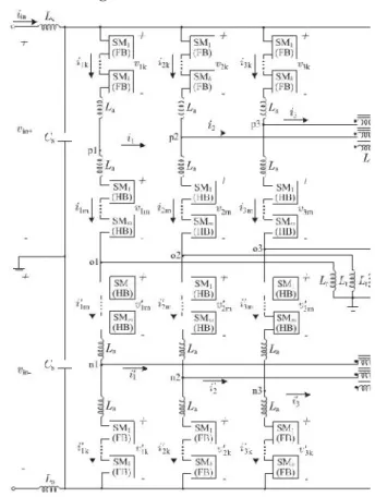
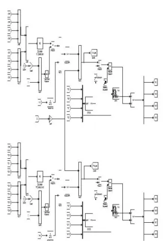
Figure. 2.1. Three-string DC-MMC architecture with input and output filtering:
(a) circuit diagram (b) switching cell configurations for j th half-bridge SM (HB/SM)
and j th full-bridge SM (FB/SM).
Fig. 2.1(a) shows the three-string architecture of the DC-MMC for deployment in bipolar HVDC networks. The DC-MMC performs single-stage dc/dc conversion by utilizing interleaved strings of cascaded SMs. Each string is comprised of two pairs of arms; each pair of arms consisting of an inner arm and an outer arm, where an arm is defined as a set of cascaded SMs. The arms of each string are
series-stacked in symmetric relation about an associated midpoint, i.e., o1, o2, o3, with the inner arms flanked by the outer arms. Each inner arm and outer arm employs m half-bridge SMs (HB/SMs) and
k full-bridge SMs (FB/SMs), respectively. Circuit
configurations for the HB/SM and FB/SM switching cells are given in Fig. 2.1(b). Arm chokes La accommodate the switching action of the SMs. A path, enabled here by inductor Lr, links the strings together via their midpoints and serves to establish circulating ac currents required by the dc/dc conversion process. Input filtering for the DC-MMC is optionally provided by Ls and Cs. However, output filter element Lf is necessary to attenuate ac voltages present at the dc output nodes of each string. The magnetizing inductance Lf of each set of coupled inductors is suitable to provide the large impedance needed for attenuation of the ac output filter currents. Moreover, use of coupled inductors as shown ensures cancellation of dc flux within the core. Capacitors Cf are a practical consideration to sink high-frequency ac currents introduced by switching action of the SMs. The use of passive elements Lf and Cf is a relatively low cost and simple implementation as compared to alternative active-filtering solutions. General sizing considerations for the output filters is provided in the Appendix. In comparison to the three-phase dc/ac MMC, the three-string architecture in Fig. 2.1 shares a similar modular structure. As will become more apparent in subsequent sections, the three-string implementation of the proposed DC-MMC may be viewed as the three-phase dc/ac DC-MMC structure adapted for single-stage dc/dc conversion. Unlike the recently proposed dc/dc converter which is formed by series-stacking two conventional three-phase dc/ac MMCs, the operation and control of Fig.2.1 is fundamentally different from that of the dc/ac MMC.
2.2. Two-String Architecture
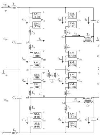
Fig. 2.2. Two-string DC-MMC architecture with input and output filtering.
2.3. Principle of Operation
In Figs. 2.1 and 2.2, the input network voltages vin+
and vin– can be unevenly split between the arms of
each string. For example, arm voltages v1k (outer
arm) and v1m (inner arm) can have unequal dc
components that sum to vin+. The same applies to vʹ1m
(inner arm) and vʹ1k (outer arm) with vin−. Division of
vin+ and vin−as described is achieved by controlling
the number and polarity of SM capacitors inserted along each string via switching action, where possible switching states for the jth HB/SM and FB/SM are vsmj= {0, +vcj} and vsmj={0,−vcj, +vcj},
respectively. The output network, represented by
vout+ and vout−, is coupled across the inner arms of each string as shown. DC power transfer between networks can be reversed by changing polarity of iin. Bidirectional dc power transfer is easily accommodated as the SMs inherently permit bidirectional current flow. The arrangement of HB/SMs and FB/SMs in Figs. 2.1 and 3.2 permits both step-up and step-down voltage level conversion for the DC-MMC. The voltage conversion ratio D and its complement D are defined as
≙ = (3.1)
′≙ 1 − (3.2)
From (3.1) and (3.2) the operating modes of the DC-MMC are summarized:
1) step-down operation: 0 < D < 1 and thus 0 < D < 1;
2) step-up operation: D > 1 and thus D < 0. For step-down operation where the voltages at nodes p1, p2,p3 (and n1, n2, n3) relative to ground always remain below vin+ (and above−vin−), the FB/SMs in
Fig. 1 and Fig. 2 need only function as HB/SMs. That is, the FB/SMs can be replaced with HB/SMs1 as long as the outer arms of each string are never required to inject negative voltages. However, by exploiting the additional switching state (i.e., vsmj=−vcj) provided by FB/SMs,
the aforementioned node voltages can exceed their respective dc input rails. This enables step-up operation and thereby the ability of the DC-MMC to interconnect HVDC networks of similar voltage levels. The range of permissible voltage conversion ratios depends primarily on the SM ratio k to m and maximum allowable SM capacitor voltage. Thus,
vout+and vout−can be generated within a range of
step-up and step-down voltage conversion ratios, without the use of an intermediate ac transformer.
Step-up capability for the DC-MMC is in practice most beneficial for values of D near unity. Designing for larger values of D, e.g., D = 1.3, is not cost effective as the input and output terminals of the DC-MMC could in this case simply be “swapped”
and the voltage conversion ratio changed accordingly, e.g., D = 1/1.3. However, by designing for a small stepup range around unity, for example, 0.9 < D < 1.1, the DCMMC can accommodate both networks fluctuating around their nominal values. This would otherwise be impossible to achieve using only HB/SMs. The DC-MMC’s ability to
interconnect HDVC networks of similar voltage levels is a significant operational advantage, as future HVDC grids will likely be formed in part by meshing together smaller preexisting dc grid segments—some of which will assuredly be at similar voltage levels.
Figure. 2.3. Principle of operation for two-string DC-MMC architecture in Fig. 2.2: DC current (solid lines) and circulating ac current (dotted lines) paths are shown. Average ac power exchange between arms (Pac ) for SM capacitor
charge balancing is indicatedby the bold arrows.
It is also possible to link the string midpoints using capacitors, however, this is done at the expense of high-impedance (capacitively) grounding the DC-MMC structure. Based on the above discussion, the principle of operation of the two-string DC-MMC architecture is conceptualized in Fig. 2.3. As the two-string and three-string architectures have the same operating principle, the former is chosen here for simplicity. DC current paths are shown with solid lines while circulating ac current paths are represented using dotted lines. Pac
signifies the average ac power exchanged between each pair of arms for SM capacitor power balancing. A nonzero dc power transfer (i.e., iin= 0) necessitates
a nonzero Pac to keep the SM capacitor voltages
balanced. The polarity of ac power exchange between arms depends on the DC-MMC operating mode. Although this balancing process will be analyzed later, a simple visual indicator of its necessity is that the dc current carried by each outer arm relative to the adjacent inner arm are of opposite directions. The requisite Pacis achieved through the interaction of the
circulating ac currents and ac components of the arms voltages. The shuttling of average ac power between arms is done in a near lossless manner as the circuit impedance consists of reactive elements. This power transfer mechanism, a well-known concept in traditional ac power systems for transferring average power between networks, is the key enabling mechanism by which single-stage dc/dc conversion for series-cascaded SMs is realized. An important characteristic of the topology in which also applies for Fig. 2.1, is the inherent symmetry in ac current paths about the converter midpoint. This symmetry, enabled by the physical linking of string midpoints, is
exploited to achieve natural cancellation of ac voltages across the input and output dc terminals.
3. ANALYSIS OF DC-MMC OPERATION
In Section 3.3 introduced the bipolar DC-MMC architecture and provided an overview of its principle of operation. This chapter discusses the DC-MMC operation in greater depth, by utilizing a simplified string model to study the ideal single-stage dc/dc conversion process. Based on the analysis, a modulation scheme for the ac arms voltages that satisfies SM capacitor power balance for all possible operating modes is proposed. Unless otherwise indicated, the following assumptions are enforced: 1) each arm has a large number of SMs such that ideal sinusoidal ac voltages are synthesized; 2) ac voltages and currents are represented by their steady-state fundamental frequency components; 3) resistance terms are neglected; and 3) ac output filter currents are negligible. The last assumption implies Lf is sufficiently high such that, for each string, the ac filter currents are small relative to the ac component of the arms currents, e.g., |˜i1| |˜i1k|, |˜i1m| and |˜i1| |˜i1k|, |˜i1m|. The notation˜i denotes the fundamental
frequency component of i, i.e., ˜i(t) = Iˆ cos(wmt +θi). 3.1. Single-Stage DC/DC Conversion Process
each arm are represented with ideal voltage sources, which is common practice in dc/ac MMC analysis. These sources model both the dc and fundamental frequency ac components of the arms voltages. All currents are separated into their dc and ac parts with
n denoting the number of interleaved strings, e.g., n =
2 for Fig. 3.2. Observe from Fig. 3.1, the dc current through the inner arms increases as D becomes smaller. For D<0.3, the inner arms carry a dc current greater than |iin/n|. This operating region thus incites
high conduction losses, and may necessitate additional inner arms installed in parallel to avoid derating of power transfer between networks. The ability to parallel multiple arms is enabled by the inclusion of La in each arm.
Fig. 3.1. Simplified model for string #1 of DC-MMC in Figs. 3.1 and 3.2, with ideal output
filtering and ac filter currents neglected.
Restructuring of arm chokes in Figs. 3.1 and 3.2 to eliminate individual chokes is possible, provided the basic requirement of an inductance in every voltage loop is not violated. Each string follows the dc/dc conversion process in Fig. 3.1. The outer arms and inner arms of each string carry a dc current of |iin/n | and |(Dʹ /D)iin/n |,
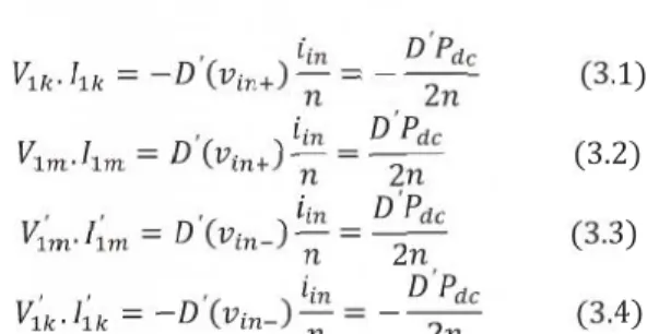
respectively. To ensure steady-state power balance of
each SM capacitor in string #1, the following average power constraints must be met:
. = − ′( ) = − ′
2 (3.1)
. = ′( ) =
′
2 (3.2)
′ . ′ = ′( ) =
′
2 (3.3)
′ . ′ = − ′( ) = −
′
2 (3.4)
V1k· I1kdenotes the phasor dot product, i.e., V1k· I1k
= (Vˆ Iˆ/ 2)cos(θv − θi). The notation V1k and I1k
signifies the fundamental frequency ac rms phasors for v˜1k and ˜i1k, respectively. That is, V1k =
(Vˆ/√2)∠θv and I1k = (Iˆ/√2)∠θi. Pdc is the total dc
power transfer between networks, as shown in Fig. 3.1, where Pdc > 0 corresponds to iin> 0. Power
balance constraints (3.1) through (3.3) reveal an average ac power equal to |Dʹ Pdc/2n| must be
exchanged between each outer arm and the adjacent inner arm. This is the same power exchange as given by Pac in Fig. 3, however, in Fig. 3 the polarity is explicitly shown. The direction of power exchange depends on the polarities of D (step-up/step-down) and Pdc (dc power transfer direction). For example, Fig. 3 shows the outer arms must deliver average ac power to the inner arms for: 1) D >0, Pdc> 0; and 2) D < 0, Pdc< 0. A set of constraints similar to (3.1)
through (3.3) can be formulated for the remaining string(s) in Figs. 3.1 and 3.2. To ensure a net ac voltage is not impressed across the input or output dc terminals, requirements are imposed on the synthesized arms voltages
= − ′ (3.5)
= − ′ (3.6)
In general, symmetry constraints similar to (3.3) and (3.6) are imposed on each string. Taking into consideration the phase shift between modulating waveforms of each string, interleaving of strings as shown in Figs. 3.1 and 3.2 offers natural cancellation of ac output inductor currents independent of D. For
example, ˜i1 and ˜i2 in Fig. 3.2 always sum to zero as
they are phase shifted by 180◦. As a result, Cf ideally carries zero current and pole voltages vout+ and vout
− are free of fundamental frequency ac stimuli. However, in practice Cfwill carry a small amount of
high-frequency current due to switching of the SMs. Based on the preceding discussion, the DC-MMCs in Figs. 3.1 and 3.2 internally circulate a total average ac power of |D Pdc |. Note interconnecting two
circulate 30% of the total dc power transfer in terms of ac power.
3.2. Steady-State Power Balance of SM Capacitors
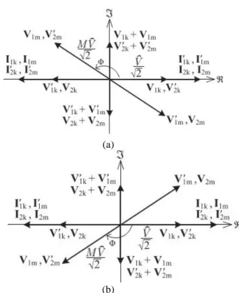
There are infinitely many combinations of ac arms voltages and resulting ac arms currents that can satisfy power balance constraints (3.1) through (3.3) and arms voltage constraints (3.3) and (3.6). The same notion applies to a similar set of equations that can be formulated for the remaining string(s) in Figs. 3.1 and 3.2. However, only the two-string architecture is analyzed in this section as it is the simplest multistring implementation of the DC-MMC. In particular, ac phasor diagrams used in converter analysis are simplified, ensuring key aspects of the single-stage dc/dc conversion process are clearly illustrated. Fig. 3.2 gives two example ac phasor diagrams that illustrate the fundamental power transfer mechanism employed to achieve steady-state power balance of each SM capacitor in Fig. 3.2, for all possible operating modes of the DC-MMC. The peak magnitude of the ac arms voltages is denoted by
Vˆ . Φ is the phase shift between ac voltages of each
outer arm and the adjacent inner arm, with positive
values of Φ defined for the inner arm voltage leading
the outer arm voltage. For example, positive values
of Φ for string #1 correspond to V1m leading V1k and V1m leading V1k . Note the modulating waveforms of each string are displaced by 180◦.
It is easy to visualize via phasor dot products that each pair of inner and outer arms in Fig. 3.2 exchange equal average ac power as dictated by (3.1) through (3.3). However, adopting such a strategy constrains each pair of arms to equally share the reactive power requirements of the composite load formed by Lrand La. This implies each arm operates
at an equal ac power factor (in Fig. 3.2, the example
case of power factor equal to 0.707 is shown where Φ
= ±90 ◦). A preferred strategy is to impose unity power factor on the outer arms while realizing near unity power factor operation for the inner arms as shown in Fig. 3.3 Here, M is the ratio of inner arm to outer arm ac voltage magnitudes, e.g., M = |V1m/V1k |. For a fixed Vˆ, this modulation scheme minimizes
the circulating ac currents needed for the dc/dc conversion process when operating with larger values of D. Moreover, it significantly reduces the circuit reactance required to establish the circulating ac currents. Based on Figs. 3.1 and 3.3, the average power exchanged between each outer arm and the adjacent inner arm is
(a)
(b)
Fig. 3.2. Fundamental frequency ac rms phasor diagrams that illustrate the power transfer mechanism used to achieve power balance of SM
capacitors in Fig. 3.2, with ac output filter currents neglected, valid for: (a) D < 1, iin> 0 and
D > 1, iin< 0; (b) D < 1, iin< 0 and D > 1, iin> 0.
/ = 3 sin (3.7)
Where
= ( + ) (3.8)
Positive values of Pk/m denote average ac power
delivered from each outer arm to the adjacent inner arm of the same string. In general, Pk/m is adjusted
by changing any combination of M, Vˆor Φ.
Converters designed with smaller Xr offer reduced
circuit var requirements and result in values of |Φ|
approaching 180◦. Equation (3.8) reveals the DC-MMC can in fact be operated with Lr equal to zero.
(a)
(b)
Figure. 3.3. Fundamental frequency ac rms phasor diagrams depicting modulation strategy to ensure power balance of SM capacitors in Fig. .2.1 while imposing unity power factor on outer arms
and near unity power factor operation on inner arms, with ac output filter currents neglected, valid for: (a) D < 1, iin> 0 and D > 1, iin< 0; (b) D
< 1, iin< 0 and D > 1, iin> 0.
Fig. 3.2 (and similarly Fig. 3.1) can be connected together and, possibly, or, if desired, solidly grounded. In this case, the arm chokes solely provide the reactance needed to setup the circulating ac currents. However, it must be stressed midpoint inductors Lrneed only to carry ac currents while arm
chokes La must carry both dc and ac currents.
Allocation of circuit inductance to Lrversus Lais the
outcome of a converter design optimization, which therefore enables cost reduction and is outside the scope of this paper. The simulations utilize a nonzero
Lr. Equating (3.7) with the required average power
exchange as dictated by (3.1) through (3.3) gives
3 sinΦ=
′
2 (3.9)
Power balance criteria (3.9) is a primary design equation quantifying the amount of average ac power that must be exchanged between arms in steady state, as a function of the voltage conversion ratio and dc power transfer between HVDC networks. Furthermore, (3.9) provides additional insight into DC-MMC operation as it relates ac and dc power
transferred through the mechanisms,by substituting n=2
reveals each pair of arms in Fig. 2 exchange |DʹPdc/3|
of average ac power via circulating ac currents.
4.1 SIMULINK DIAGRAMS :
4.1.1. Proposed simulink model diagrams:
Figure 4.1 Two string DC-MMC architecture with input and output filtering.
Figure 4.2 block diagram of half wave bridge. 4.1.3. circuit diagram for half wave bridge:
Figure 4.3. Switching cell configuration for half wave bridge.
4.1.4. Submodules of full wave bridge:
Figure 4.4. block diagram of full wave bridge. 4.4.5. circuit diagram for full wave bridge:
Figure 4.5. Switching cell configuration for full wave bridge
4.4.6. Control stragey of half wave bridge:
Figure 4.6. open loop voltage & current control of half wave brige
Figure 4.7. open loop voltage & current control of full wave brige
4.1.8. Ouput:
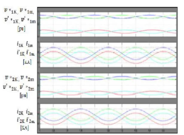
Figure 4.8. Simulation results for two-string DC-MMC.
4.1.9. Simulation Results:
Two operating scenarios for the two-string DC-MMC are simulated in PLECS to validate the open-loop voltage control strategy proposed. The scenarios include: 1) D = 0.5 (step-down); and 2)D = 1.1 (step-up). For each scenario, the dc power transfer between networks Pdc is 14MW. A full switched model of Fig. 3.2 is implemented with four SMs per arm, i.e., k =m = 4; ideal switches are utilized. In both cases iin> 0 (and thus Pdc> 0) such that Fig. 3.3(a) and (b) is utilized. To ensure power balance of SM capacitors, the two-string DC-MMC must exchange DʹPdc/4 of average ac power between inner and outer arms (see Fig. 3.1). The fundamental modulating frequency of the arms voltages is selected as 50 Hz. The APOD SPWM scheme is adopted, although alternative modulation schemes can be used. .In the subsequent discussions, the string model in Fig. 5.1 and phasors diagrams in Fig. 5.3 are heavily leveraged in comparing simulation results with the DC-MMC analysis
Step-Down Operation:
Figure. 4.9. Simulation results for two strings DC-MMC with D=0.5 and iin>0; V= 3.5kVPK, Vncap
=2.2kv, Ls=0mH, Cs=0µF.
The dc input and output voltages are ±8.8 and ±4.4 kV, respectively. iin and iout have average values of 0.795 and 1.59 kA, respectively. For the DC-MMC to facilitate the transfer of 14 MW, each outer arm delivers DʹPdc/4 = 1.75 MW of average ac power to the adjacent inner arm (i.e., Pk/m = +1.75 MW). This is achieved with an ac voltage for the outer arms of ˆV =3.5 kVpk and circulating ac currents of 1.0 kApk.
Fig. 4.4 shows the ac currents in the arms circulate in a symmetric fashion about the converter midpoint as dictated by Fig. 4, e.g.,˜i1k=˜i1m=−˜iʹ1m = −˜iʹ1k. All of the arms have the same dc current magnitude of 0.398 kA (iin/2) due to the fact Dʹ= D = 0.5. However, outer arms currents i1k ,iʹ1k, i2k, iʹ2k have a positive average value (+0.398 kA) while inner arms currents i1m,iʹ1m, i2m, iʹ2mhave a negative average value (–0.398 kA). The opposing polarity of dc arms currents aligns with Fig. 5.1 and is a result of the DC-MMC operating in step-down mode. As demonstrated by i1, i2 and iʹ1 iʹ2 waveforms, Lf imposes a large ac impedance and confines the circulating ac currents within the DC-MMC structure. This validates the prior assumption of negligible ac output inductor currents.
In Fig. 4.4, the ac components of the arms modulating signals (i.e., scaled versions of ac arms voltages) and ac components of the arms currents align with the phasor diagram in Fig. 3.3(a). Average ac power is delivered from each outer arm to the
adjacent inner arm, with outer arms operating at unity power factor and
inner arms supplying the necessary vars. For
example, and in Fig. 8 are phase-shifted 180◦(outer arm delivering average ac power at unity power factor) while slightly lags˜i1m (inner arm receiving average ac power near unity power factor and supplying vars). To supply reactive power the inner arms have a slight larger ac voltage magnitude relative to the outer arms, as illustrated in Fig. 3.3(a).SM capacitor voltage waveforms plotted for string #1 verify charge balance is achieved via the described power transfers. Similar waveforms exist for string #2. The balancing of SM capacitor voltages as shown validates the adopted closed loop ac current control strategy. As can be seen in Fig. 4.4, iinand iout contain a small second harmonic (i.e., 100 Hz) ripple component. This open-loop operating characteristic of the DC-MMC is not captured as the analysis is restricted to fundamental frequency operation. The second harmonic current ripple can be mitigated by increasing the energy storage capacity of the SMs (i.e., increasing Csm ). Furthermore, it is likely that supplemental arm voltage control can be incorporated to suppress the generation of second harmonic voltages, similar to the dc/ac MMC. For this case study, the SM capacitors are sized to achieve acceptable 100-Hz current ripple as well as tolerable capacitor voltage ripple.
Figure 4.10: Simulation results for two-strings DC-MMC with D=1.1 and iin>0; V= 1.2kVPK, Vncap
=2.9kV, Ls=0.5mH, Cs=40µF.
The input voltage of ±8.8 kV is now stepped up to ±9.68 kV. This scenario is chosen to
demonstrate the DCMMC’s ability to interconnect dc
networks of similar voltages by exploiting FB/SMs in the outer arms. The average value of iin remains the same as for step-down mode (0.795 kA), however, iout now has an average value of 0.723 kA due to the relation iin = Diout. For the same Pdc= 14MW, only 0.35 MWof average ac power is exchanged between arms in F as opposed to the 1.75 MW needed for step-down operation with D = 0.5. This is because |Dʹ| has decreased from 0.5 to 0.1. However, as Dʹ=
−0.1 but Pdc remains positive, the polarity of power exchange has reversed and is now from inner to outer arms (i.e., Pk/m =−0.35 MW). This is achieved with
ˆ V = 1.2 kVpk and circulating ac currents of 0.583 kApk.
The average value of outer arms currents i1k ,iʹ1k, i2k, iʹ2k in Fig. 9 remains unchanged from the simulated step-down scenario (+0.398 kA), which is consistent with Fig. 4.1. The dc component of inner arms currents i1m ,iʹ1m, i2m, iʹ2m, however, is now +0.036 kA, i.e., flowing toward the neutral, as necessary for boost operation. Relative to the outer arms, the inner arms of the DC-MMC need only carry a small amount of dc current for values of D near unity.
In Fig. 4.10, the ac components of the arms modulating signals and the ac arms currents align with the phasor diagram in Fig. 4.3(b). Average ac power exchange is now from each inner arm to the adjacent outer arm. The outer arms still operate at unity power factor while the inner arms supply vars.
For example, and in Fig. 6.10 are in phase (outer arm receiving average ac power at unity power factor) while lags by nearly 180◦(inner arm delivering average ac power near unity power factor and supplying vars). The described waveforms demonstrate the DC-MMC’s ability to meet power
balance of each SM capacitor while performing step-up voltage level conversion.
To facilitate step-up operation the nominal voltage of each SM capacitor in Fig. 4.10 has increased from 2.2 to 2.9 kV. This increase in Vncap which for simplicity in this case study is imposed for all arms, permits the inner arms to achieve the dc output voltage required for step-up mode.
In comparison to Fig. 6.9, the waveforms for step-up operation display significantly more switching ripple content. This stems from using a relatively low number of SMs in each arm (four) in order to reduce the simulation complexity and run time.To compensate for the low number of SMs, the arm choke inductance and SPWM carrier frequency are selected to accommodate the added ripple during step-up. In addition, input filter elements Ls= 0.5 mH and Cs= 40μF are utilized for the stepup scenario to reduce switching ripple for iin . For the step-down scenario, an input filter is not required. This is affirmed by very low switching ripple content in Fig. 4.9. Note, in both Figs. 4.9 and 4.10 the DC-MMC can provide bidirectional fault blocking as the outer arms have sufficient voltage to withstand the larger of the input or output dc terminal voltages.
5.1 Fuzzy rules:
5.2 Membership Functions
A membership function (MF) is a curve that defines how each point in the input space is mapped to a membership value (or degree of membership) between 0 and 1. A membership function for a fuzzy set A on the universe of discourse X is defined as µ A: X→ [0,1], where each element of X is mapped to a
value between 0 and 1. This value, called membership value or degree of membership, quantifies the grade of membership of the element in X to the fuzzy set A. Membership functions allow us to graphically represent a fuzzy set. The x axis represents the universe of discourse, whereas the y axis represents the degrees of membership in the [0,1] interval. Simple functions are used to build membership functions. Because we are defining fuzzy concepts, using more complex functions does not add more precision. Below is a list of the membership functions we will use in the practical section of this tutorial. Triangular function: defined by a lower limit a, an upper limit b, and a value m, where a < m < b.
Fig 5.2Membership functions plots, are the input 1, input2 and output of fuzzy controller respectively. These plots are obtained according to the rules written in the fuzzy tool box and the switching process depends upon these rules
CONCLUSION
A new modular multilevel dc/dc converter, termed the DC MMC, is presented for the interconnection of bipolar HVDC networks. The DC-MMC features a new class of bidirectional single-stage dc/dc converters utilizing interleaved strings of cascaded SMs. Power balance for each SM capacitor is achieved via circulating ac currents, which are established by reactive elements linking each string.
The two-string and three-string architectures for the DC-MMC are introduced, where the latter shows similarity to the three-phase dc/ac MMC structure. In general, an arbitrary number of strings can be interleaved. By employing a unique arrangement of HB/SMs and FB/SMs for each string, the DC MMC can provide both up and step-down operations and interconnect HVDC networks of similar voltage levels. Moreover, the utilization of a sufficient number of cascaded FB/SMs in the outer arms enables bidirectional fault blocking capability similar to a dc circuit breaker.
reduces the blocking voltages of the high frequency switching operation and ripple content in the inductor. The results were analyzed through MATLAB/SIMULINK environment R2009a.
REFERENCES
[1] Gregory J. Kish, Student Member, IEEE, Mike Ranjram, Student Member, IEEE, and Peter W. Lehn,
Senior Member, IEEE” A Modular Multilevel
DC/DC Converter With Fault
Blocking Capability for HVDC Interconnects”
IEEETRANSACTIONS ON POWER
ELECTRONICS, VOL. 30, NO. 1, JAN 2015
[2] R. Majumder, C. Bartzsch, P. Kohnstam, E. Fullerton, A. Finn, and W. Galli, “Magic bus: High -voltage DC on the new power transmission
highway,”IEEE Power Energy Mag., vol. 10, no. 6,
pp. 39–49, Nov. 2012.
[3] W. Chen, A.Q. Huang, C. Li, G. Wang, and W.
Gu, “Analysis and comparison of medium voltage
high power DC/DC converters for offshore wind
energy systems,” IEEE Trans. Power Electron., vol.
28, no. 4, pp. 2014– 2023,
[4] J. W. Bialek, “European offshore power grid demonstration projects,” in Proc. IEEE Power Energy Soc. General Meet., Jul. 2012, pp. 1–6.
[5] D. Das, J. Pan, and S. Bala, “HVDC light for large offshore wind farm integration,” inIEEE Power Electron. Mach. Wind Appl., Jul. 2012, pp. 1–7.
[6] J. Robinson, D. Jovcic, and G. Joos, “Analysis
and design of an offshore wind farm using a MV DC grid,” IEEE Trans. Power Del., vol. 25, no. 4, pp.
2164–2173, Oct. 2010.
[7] C. Meyer, M. Hoing, A. Peterson, and R. W. De
Doncker, “Control and design of DC grids for offshore wind farms,” IEEE Trans. Ind. Appl., vol.
43, no. 6, pp. 1475–1482, Nov./Dec. 2007.
[8] S. S. Gjerde and T. M. Undeland, “Control of
direct driven offshore wind turbines in a
DC-collection grid within the wind farms,” in IEEE Trondheim PowerTech, Jun. 2011, pp. 1–7.
[9] A. Orths, A. Hiorns, R. Van Houtert, L. Fisher, and C. Fourment, “The European north seas countries’ offshore grid initiative—The way
forward,” inIEEE Power Energy Soc. General Meet.,
Jul. 2012, pp. 1–8.
[10] P. Fairley, “Germany jump-starts the supergrid,”
IEEE Spectr., vol. 50, no. 5, pp. 36–41, May 2013. [11] D. C. Ludois and G. Venkataramanan, “An
examination of AC/HVDC power circuits for interconnecting bulk wind generation with the
electric grid,”Energies, vol. 6, no. 3, pp. 1263–1289, 2010.
[12] R. Adapa, “High-wire act: HVDC technology:
The state of the art,”IEEE Power Energy Mag., vol.