1
Notion Of Artificial Labs, Slow Global Warming
And Advancing Engine Studies: Perspectives On
A Computational Experiment On Dual-Fuel
Compression-Ignition Engine Research
Tonye K. Jack, Emmanuel N. Nyeche
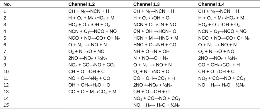
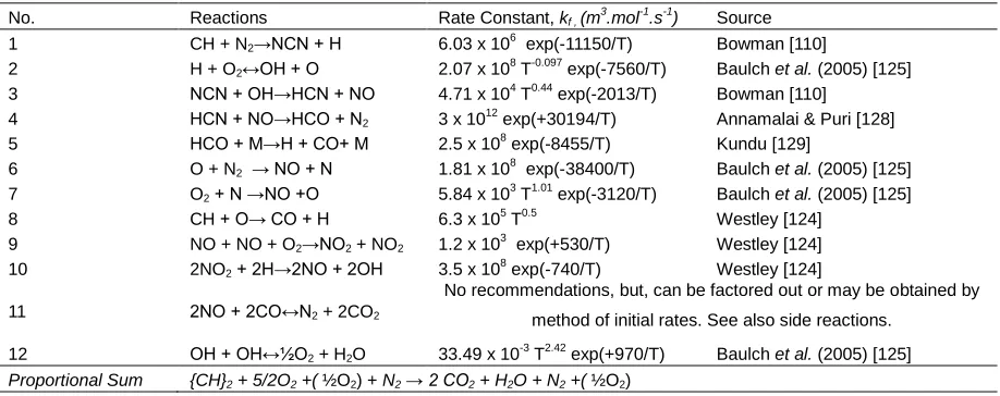
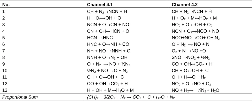
Abstract: To appreciate ‗clean‘ energy applications of the dual-fuel internal combustion engine (D-FICE) with pilot Diesel fuel, to aid public policy formulation in terms of present and future benefits to the modern transportation, stationary power, and promotion of oil and gas ―green- drilling‖, the brief to an engine research team was to investigate the feasible advantages of dual-fuel compression-ignition engines, guided by the following concerns: (i)
Sustainable fuel and engine power delivery? (ii) The requirements for fuel flexibility? (iii) Low exhausts emissions and environmental pollution? (iv)
Achieving low specific fuel consumption and economy, for maximum power? (v) The comparative advantages over the conventional Diesel engines? (vi)
Thermo-economic modeling and analysis for the optimal blend as basis for a benefit/cost evaluation? Planned in two stages for reduced cost and fast turnaround of results - initial preliminary stage with basic simple models, and advanced stage with more detailed, complex modeling. The paper describes a simplified MATLAB based computational experiment predictive model for the thermodynamic, combustion and engine performance analysis of dual-fuel compression-ignition engine studies operating on the theoretical limited-pressure cycle with several alternative fuel-blends. Environmental implications for extreme temperature moderation are considered by finite-time thermodynamic modeling for maximum power, with predictions for pollutants‘ formation and control by reaction rates kinetics analysis of systematic reduced plausible coupled chemistry models through the NCN reaction pathway for the gas-phase reactions classes of interest. Controllable variables for engine-out pollutants emissions reduction and in particular NOx elimination are identified. Verifications and Validations (V&V) through Performance Comparisons were made using a clinical approach in selection of Stroke/Bore ratios greater-than and equal-to one (≥1), low-to-high engine speeds, and medium to high power requirements from data of existing dual-fuel engines and convertible real diesel engines applied in different industry sectors. The results obtained show that dual-dual-fuel engines operating on limited-pressure cycle have economical and environmental advantages in terms of engine efficiency, and fuel consumption; with the engine emissions results showing promise of operating within the desired United Nations‘ guide for slow climate change, with reduced carbon dioxide (CO2).
Index Terms: Alternative Fuels, Compression-Ignition Engines, Diesel Engine, Dual-Combustion Cycle, Dual-Fuel Engine, Engines, Internal Combustion Engine, Limited-Pressure Cycle, Marine Engines, MATLAB, Pollutant Control, Simulation.
————————————————————
1 Introduction
THE three terms: Renewable, Alternative and Sustainable when applied to Energy, are used interchangeably to describe sources different from depleting fossil-based energy. In current use, the terms are also used to describe better management of fossilised sources of energy due to the finite global reserve limits of exploited and exploitable natural resources, and conformable control measures by concerned Countries‘ Governments in periods of risks to energy stability. Such risks, affect economic planning, due to energy price escalation and the attendant ripple effects on inflation in every sector of a Country‘s economy. Preventive approaches to the risks depend on seeking economically, and politically feasible alternatives. Several such alternatives have been investigated and applied.
In this paper, the Dual fuel alternative for internal combustion engines (ICE) is of interest. Applied in several industrial sectors, the benefits of the dual-fuel internal combustion engine (D-FICE) alternatives that offer attractive options for safety critical, and often uncertain applications in areas such as: sea-going marine vessels, municipal bus services, and military operations are: (a.) greatly reduced emissions, (b.) retention of conventional diesel engine torque and high power characteristics, (c.) safety and energy security in terms of emergency switch-over to diesel, (d.) reduced maintenance costs [1]. Marine, Military, Municipal Bus Services and Oil Drilling Applications dominate the current use of the dual-fuel Compression-ignition engines [2], [3], [4], [5]. The major attraction! Fuel supply flexibility, and interchange in remote areas where fuel supply is limited, energy security in particular reference to Military war time and emergency needs, and fuel costs; a very interesting application being, in Marine Liquefied Natural Gas (LNG) ships; where there is need to utilize the extractable energy from the boil-off (natural boil-off gas, called N-BOG) or evaporating gas, economically [6]. In other applications, the LNG is stored in tanks [5], [2]. The Dual-Fuel Compression-Ignition engine operates on two modes: (i) The ―Gas mode‖ – in which an environment friendly alternative ―primary fuel‖ is mixed with air at inlet, and at just towards the end of the compression stroke, a pilot diesel fuel is injected at high pressure, and acts as a ―liquid spark plug‖, taking advantage of the heat of compression to initiate ignition and combustion; (ii) the Diesel mode – where the engine operates predominantly on the Diesel Fuel [7], [8], [4]. In this paper, the terminology ―Gas mode‖ is generalised and applies to the atomised state and mode of delivery of any of the possible alternative ―primary fuels‖ that may be used during the __________________________
Tonye K. Jack is a Registered Engineer, with industry and engineering design consulting experience. He taught Mechanical Engineering classes at the then Rivers State University of Science and Technology (now Rivers State University) and more recently at the University of Port Harcourt.; Tel: +234 803 676 6323; E-mail:
compression stroke, (natural gas, LNG, biogas, ethanol, methanol, etc.) [9], [5], [4], [3], [2]. Thus, one major opportunity in the Dual-Fuel Technology application is the conversion of existing Diesel engines to dual-fuel engines; this possibility of switch in fuel use, allows manufacturers of ICE to offer Diesel Engine users the options of converting their equipments to D-FICE units, if the feasibility of such conversions are thermodynamically economical and profitable (TEP) [10], [1], [3]. The feasible solution must be a dual-fuelled engine that has same or higher compression ratio, and thermal efficiency than a conventional diesel only fuelled engine, and delivers low exhaust pollutant emissions [11]. Such low exhausts emissions are achievable when there is complete chemical equilibrium in the combustion of the fuels used [12], [9]. Achieving complete combustion of the fuels requires time [13], [12], [9]. It is thus proposed in this work that, to allow time for complete combustion, the engine working cycle model to satisfactorily provide complete combustion is the limited-pressure cycle, in which, heat is added partly at constant volume and partly at constant pressure [14], [12], [9]. Nyeche [15], thus, applied the limited-pressure cycle model for the Compression-Ignition Engine, Dual-Fuel Analyzer [15] (DFA) computer-aided tool. As improvements in dual-fuel technology give encouragements to existing Diesel Engine owners to convert, two load dependent, ―knock controlled‖ technological methods of delivering the alternative ―primary fuel‖ in the atomised state are offered to end users –in steady load, the Fumigation principle, in which a homogenous blend of the alternative ―primary fuel‖ and air, is delivered at the inlet for compression; and in variable load, the gas injection methods (centre-point, multi-point or direct), whereby, inlet delivered air is first compressed and the alternative ―primary fuel‖ is injected prior to burning [16], [17], [18], [19], [11], [1]. Proper blending can be made possible with thorough use of a fuel composition sensor in which an engine control and management system (ECMS), automatically adjusts the Air-Fuel (A/F) ratio for the required blend [20]. In other technological applications, atomised delivery of the alternative ―primary‖ fuel into the cylinder manifold/chamber is by electronically controlled injector unit (ECU) interfaced with the original Diesel manufacturer‘s engine controller to deliver optimised levels of engine performance through effective gas substitution rates for minimum emissions [8], [1]. The ECU injector approach is also applied in the timed delivery of the pilot diesel [8], [11]. The concerns of: (i) Cost, (ii.) ease and simplicity of the installation, governs the choice of technological application in such operational requirements; with the fumigation method having been assessed to be the lesser expensive and simpler to apply of the two methods [1]. While current pricing of one such alternative ―primary fuel‖, natural gas, may be tied to the price of crude oil, and may appear not to make much of an operational cost difference in periods of high oil prices, it is suggested that the benefits listed have to be considered as a whole, to obtain the desired optimum dual-fuel engine usage performance. In the sections that follow, after a review of some related earlier and recent trends in D-FICE research, the considerations leading to, and requirements for the thermodynamic, combustion and performance models‘ developments in the DFA tool are presented.
2 REVIEW OF PREVIOUS RELATED WORKS
3 improving performance, Matthews [29] developed what he
called ―the Efficiency Rule‖, a separate set of relationships, of: Brake, indicated Power, indicated and mean effective pressures, indicated and brake specific fuel consumptions, as functions of the energy efficiencies of: thermal, volumetric, combustion, and mechanical efficiencies, and other engine parameters. Pirouz-Panah and Asadi [30] conducted computer-aided performance predictions of dual-fuel Diesel engines constructed with thermodynamic models of Diesel, blended separately with Liquefied Petroleum Gas (LPG) and Compressed Natural Gas (CNG) with reference to engine cycles, and in particular based on limited-pressure cycle, and the result compared to the performance of an engine operating on Diesel only fuel. Pirouz-Panah and Asadi [30] concluded that, increased gas proportion in dual-fuel engines results in higher indicated power, and indicated mean effective pressure, and thus, more work done per cycle of engine operation, with better fuel economy, without appreciable change in thermal efficiency. In a similar but experimental approach Pirouz-Panah, Sarabchi and Kosha [31] carried out experimental investigations and engine performance studies on a dual fuel (LPG-Diesel blend) direct injection diesel engine under various load conditions. The work showed that with equal power, the LPG-diesel fuel engines had better performance with improved fuel economy, and reduced emissions. They also investigated different proportions of LPG-Diesel blend and concluded that the optimal blend is 30 % LPG-70% Diesel. Ajav and Akingbehin [32] in an experimental study on some fuel properties of ethanol extracted from Nigerian sugarcane, blended with diesel fuel to determine suitability for use in compression-ignition engines, established that Diesel-ethanol blends containing 5-, 10-, 15-, and 20- percent ethanol content have similar fuel properties in comparison with Diesel; and all blends were highly flammable with flashpoint temperatures that were below the ambient, and calorific or heating values of all blends though lower than that of Diesel fuel, but, insignificant, when analysed at the 5-percent level of significance. For proper mass transfer and fulfilling metering requirements in engine operation, Ajav and Akingbehin [32] deduced that the determining factor of viscosities of the blends decreased as the ethanol content in the blends were increased. Bahri, Osman, and Oguz [33] in developing a model for natural resource preservation presented the results of a thermo-ecological optimization for optimum ICE operation, by evaluating and comparing the performance of endoreversible dual cycle ICE under: (i) maximum ecological function and (ii) maximum power conditions. The results of their investigation have a cautionary guideline note, that, since optimal values of the principal engine parameters, such as compression ratio, pressure ratio and cut-off ratio, which maximize the ecological objective function, lead to the advantage of lower entropy generation, and higher thermal efficiency, it must be noted that, on the negative side such a design results in lower power output. In related experimental investigation to Ajav and Akingbehin [32] on a single-cylinder, direct injection CI engine with modified inlet duct for injection of ethanol, Kowalewicz and Pajączek [34] showed that ethanol to diesel fuel ratio up to over 50-percent may be applied, with engine thermal efficiency increased at increasing load, and observed reductions in, soot, green house gas (CO2) and NOx emissions. Alexandrov, Orlov, and Ochkov [35] using MathCad, MatLab, Mathematica and Maple developed tools for interactive mode thermodynamic cycles calculations via
using (i) Diesel and Hydrogen, and (ii) Hydrogen and Compressed natural gas (CNG), to find the effects of such engine conditions as: the optimum mixture strength through an equivalence ratio, and combustion temperature and pressure on quality of exhaust emissions. Joshi, Poonia, and Jethoo [46] presented the results of a mathematical model of a Liquefied Petroleum Gas (LPG) – Diesel Dual-Fuel Engine investigation through a computer simulation for optimising and predicting the engine performance and combustion characteristics. Brusstar [47] in a major methanol policy conference forum presentation by the United States Environmental Protection Agency (USEPA) highlighted the Dual Fuel Diesel (D)-Methanol (M) engine performance (better efficiency) and emission (no exhaust after treatment) advantages of D50/M50 and D10/M90 when compared to conventional Diesel Blends, D100/M0, on a brake mean effective pressure (BMEP) and brake thermal efficiency (BTE) versus speed plot indicating improved performance, with the D10/M90 blend giving better results. Kargul [48] at the Diesel Engine Emissions Reduction (DEER) Conference on Fuels and High-Performance Lubricants, stated the gains from Natural gas and Methanol use as alternative fuels. Kargul [48] reported a 5-percent efficiency advantage over conventional Diesel. In studying Methane-Diesel Dual Fuel (DDF) engine option, Königsson [49] highlights the main challenges of DDF operation and suggests early pilot Diesel Injection to achieve Homogenous Charged Compression-Ignition (HCCI)/Reactivity Controlled Compression-Ignition (RCCI) type combustion with combustion phasing controlled by the Diesel-to-Methane ratio to overcome limits to performance and emission at light loads. Christen and Brand [50] proposed needed technology building blocks, and presented the results of a simulation study applying the concept of Miller cycle, two-stage turbo-charging and variable valve timing and control management with the objective of improving fuel consumption and meeting the requirements for International Maritime Organisation (IMO) Tier 3 NOx emissions regulations in both Diesel and Dual fuel engines. Asghari and Mousavi [51] in a similar work to that of Bahri etal. [33], studied the operational performance of dual-combustion cycle engines with variable specific heat capacity, and considering heat loss by assuming approximately constant cylinder wall temperature, and friction loss of the piston, together with key engine parameters, derived optimum relationships for the power output and thermal efficiency of working fluid using finite time thermodynamics analysis. Peter [52] in studying the effects of natural gas substitution rates on a large dual fuelled (Natural Gas-Diesel) engine performance under varying load conditions and constant speed, reported that engine power remains unchanged for substitution rates up to 40 %, but decreases with higher substitution rates; furthermore, Peter [52] deduced that engine economy in terms of brake specific fuel consumption is affected with Natural Gas substitution rates beyond 50 % performance, and with serious consequences of unacceptable hydrocarbon and carbon monoxide pollutant emissions with Natural Gas substitution rates up to 80%. Brenneisen et al. [53], investigated the performance improvements on running rural community Electricity Powered Diesel Generators on Dual Fuel Diesel-and-Fuel-gas-from-burnt-Biomass as part of supporting the social and community programs of a Brazil Government Diesel Power project with reported saving in Diesel use, 43.8% increase in power, as result of stable voltage and a maximum current at the generator, and per kilowatt savings in energy
cost to the consumer. Ramjee, Reddy and Kumar [54] reported an over 75-percent improvement in performance and reduced emissions in Diesel –Compressed Natural Gas (CNG) Dual Fuel Mode Engines when compared to Diesel only fuelled engines. While in a similar work, Ehsan and Bhuiyan [55] reported an 88 % improvement in Dual Fuel Mode performance over conventional Diesel. Azimov, Tomita, and Kawahara [56], document the results of combustion mode analysis experiments of dual fuelled engine model types (Natural gas; Diesel Synthesis Gas; and Diesel-Hydrogen Gas), and suggested the use of PREMIER
5 using Hydrogen in Dual Fuel Compression Ignition engines.
Rashidi, Hajipour and Fahimirad [61], investigated the effects of initial temperature, combustion and heat transfer factors on the efficiency, and the net work output of an air-standard Dual cycle. Inyeni, Jack, and Etebu [62], developed application software for Diesel engine thermodynamics and engine performance analysis using MATLAB. The software provides a fast calculation of diesel engine parameters and takes care of the tedium of repetitive hand calculations when parameter(s) values vary.
3 ENGINE CYCLE PROCESS
For Heat Engines, a cycle process analysis is essential to produce driver power from the work of heat [63]; and, to achieve full and complete burnt combustion of the fuels, time is needed [12], [13]. In that regard, for efficient engine thermodynamic performance of the dual-fuel engine, an engine cycle model based on limited-pressure cycle was adopted in developing the DFA tool. This engine cycle, also known as dual combustion cycle or Trinkler cycle proposed by the Russian Engineer, Gustav Trinkler in 1904 [64], [14]). In this cycle, heat is added in two stages – a part at constant volume and the final at constant pressure [13], [63]; and with the two stage heat addition processes as applied in a D-FICE, ignition centers are created for continuous turbulent flame propagation throughout the gaseous fuel-air mixture from timed-ignition of the injected Diesel fuel, and with the increased admission of alternative fuel such as natural gas leading to improved engine performance, for any quantity of diesel fuel [42], which agrees with the PREMIER [56] concept. In Fig. 1 is the theoretical limited-pressure or dual combustion cycle operation pressure-volume (P-V) diagram.
3.1 Decisions on Input Parameters and Development of Graphical User Interface (GUI) for the Dual Fuel Analyser (DFA) Models
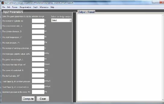
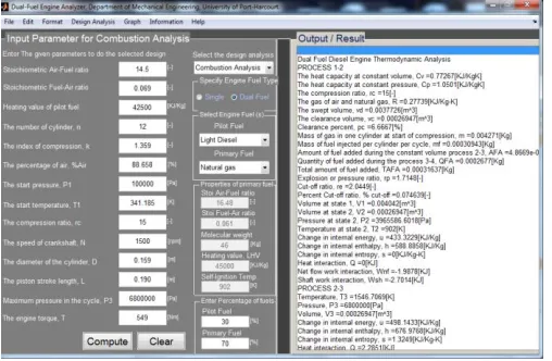
The Dual Fuel Analyser (DFA) [15] program provides computation models for thermodynamics, engine performance and combustion analyses. The decisions on the necessary input parameters for proper analysis were guided by reported achievements from some open literature (both experimental and analytical), typical available nameplate engine data from Diesel engine manufacturers, manufacturers‘ brochures, and recommendations in the literature on acceptable standard inputs for the dual fuel engine, dual-combustion cycle. The general program launch GUI is as shown in Fig. 2. In Fig. 2, the Drop-Down design analysis Select options are: Thermodynamic Analysis; Engine Performance Analysis;
Combustion Analysis Modelling.
3.2 Thermodynamics Analysis Program Sequence Modelling
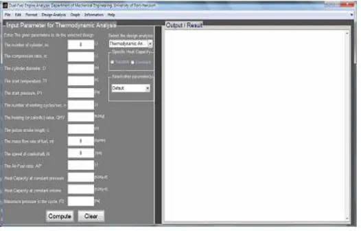
The thermodynamics analysis dual fuel engine model applied is derived from the processes involved in the limited-pressure cycle and the first law of thermodynamics. The model can predict the behavior and properties of the working fluid(s) in the cylinder of D.F engine. Fig. 3 shows the GUI for the Thermodynamic Analysis model; the check options allowing for variable or constant specific heat analysis; and the other drop-down offering additional input capabilities. As much as possible, Equations’ numbers for the Thermodynamic Analysis model computations have been written in order of Sequence Logic as applied for program reasoning. In developing the DFA program, the objective was to have a Dual-Fuelled engine, with similar or improved performance in comparison to a Diesel fuelled engine. The basis question was: Which {thermodynamic functional(s) parameters, and engine Mechanical (geometrical) parameters}; will give OPTIMISED {Fuel Economy parameters; at same or optimal Power Requirements and reduced emissions}? Expressed mathematically: Which {thermodynamic functional(s) (rC, rP, rE, k), and engine Mechanical (geometrical) Parameters (D, L, nc, Vs)}; will give OPTIMISED {{Fuel Economy Parameters (ISFC, BSFC, η); at optimum Power Requirements (IP, BP, TQ, N) and reduced emissions (HC, CO2, CO, NOx)}? Typical Engine terms apply, as in functionals: rC = compression ratio; rP = pressure-ratio; rE = cut-off ratio; and k = specific-heat ratio. Geometric properties are: D = Bore Diameter; L = Stroke length; nc = number of cylinders; and Vs = swept volume.
Fig. 2. General launch graphical user interface of DFA software.
Pmax
QH,1
3
1 2
4
5 QH,2
exh
P1
vc vd
Volume
Pr
es
su
re isentropic
Fig. 3. DFA thermodynamics analysis module input GUI
3.2.1 Temperatures, Volumes and Pressures
In new build Dual Fuel Engine or Diesel-to-Dual fuel Engine conversion technologies, the thermodynamic principles of the Diesel engine operating limits in terms of in-cylinder temperatures and pressures apply [8]. The state point temperatures, volumes and pressures are dependent on the non-dimensional thermodynamic functional parameters, rp, rC, rE, and k, and can be defined by the corresponding function equivalent dimensionless relationship:
v p E
C
p C
C V V T T V V P P k
r r
r , , , , , ,
3 4
3 4
2 1
2
3 (1)
Where, the symbol, Ф indicates respective function equivalence. The pressure at the end of compression, the state point 2 in Fig. 1 is:
(2)
In Fig. 3, the values recommended by ASABE [65] for a dual-combustion cycle initial conditions are atmospheric. Regulation for International Atmospheric conditions exists. The values adopted by Nyeche [15] in the Dual Fuel Analyser (DFA) Program are: initial pressure, P1 =1 bar, and at ambient inlet temperature, T1 [65]. Under Supercharge condition, more pressure is required at the inlet than at under atmospheric condition [12]. In some Countries, assumed reference Standard atmospheric datum temperatures are usually taken at 15 oC (288K), 20 oC (293 K) or 25 oC (298 K) [12], [13]. And, yet, for other Countries, it is higher. The influence of initial temperature conditions on dual cycle engine have been investigated and reported by Rashidi et al. [61]. Hardenberg and Hase [28] studied the effect of ambient temperature and pressure on pressure rise and delay. The ―rule of thumb‖ limiting condition for Diesel engine maximum compression pressure, P2, is within: 30-50 bar [13]; for Kolchin and Demidov [66], the pressure and temperature, respectively, at the end of compression are within the limits: 35-55 bar; 700 to 900 K [66]. The temperature T2, at the end of compression can be obtained from:
(3)
However, around about the temperature, T2, also defines the ignition point for the start of combustion. The condition can best be taken as the ignition temperature of the primary ―alternative‖ fuel in the dual fuel state, since in practice the air-plus-alternative gaseous fuel mixture, (within the flammability limits [24]), is compressed, until it is heated above the auto-ignition temperature of the high pressure spray injected Diesel; and, this allows for calculation of the compression ratio of the dual fuelled engine [67], [65], [63]. Thus, (3) can be rewritten as in (3a):
1 1
1 2
k
C T T
r (3a)
In separate input model options of the DFA program, the compression ratio is available as input, and, a controllable and optimisation parameter. The Compression ratio for Diesel Engines can range from: 12 – 24 [13], [9]. ASABE [65] suggests that the compression ratio be at least 16 for self-ignition [65]. For a fixed self-ignition temperature, T2, it can be confirmed by (3a) that lower values of the ambient initial temperature, T1, will result in higher compression ratio, rC. This was shown by Rashidi et al. [61] to have effect on the net work output and thermal efficiency with a series of graph plots. Note that for inlet natural inductive preheating conditions, the temperature, T1, is higher, and can range from 310-350 K for naturally aspirated Diesel Engines, and 320-400 K for supercharged four-stroke engines [66]. The ignition temperature in the single fuel dual-cycle is taken as the self-ignition temperature of Diesel Fuel. The auto-self-ignition temperatures of all the considered fuels are shown in Section 6 as obtained from the literature. The total gas volume, V1, at Bottom Dead Centre (BDC) and the Clearance volume, V2, at the Top Dead Centre (TDC) are related to the engine mechanical (geometrical) parameters {D, L, nC} and obtained as a function of the cylinder displacement volume, vd, (or Swept volume, vS); evaluation of the state point cylinder gas volumetric values follows:
Cylinder Swept or Displacement volume is:
(4)
Compression volume or Clearance Volume is:
1
2
C S C
r v V
v (5)
Percentage clearance
(6)
7 For a typical ICE application, the mass of the trapped gas, in
this case, of the Dual- Fuel engine (air- plus- gaseous or aspirated alternative fuel [19]) during the compression process remains essentially unchanged [65], and can be estimated from:
Mass, ma maf (8)
Where, ma = mass fraction of air, and maf =mass fraction of alternative fuel in the air-plus-aspirated alternative fuel; mm is more like a lumped-mass in the compression process.
The mass of air, ma aVdV (8a)
Where, the parameter, ηV, is the volumetric efficiency, to account for the admission losses in the intake valve [21], and greater than 90 % for Diesel engines [9], and under supercharge conditions could exceed 100 % [13]. Equations (2)-(8) govern the Cycle Process 1-2: Isentropic compression of Air-plus-Atomised Alternate fuel blend in this fuel, dual-cycle application of Fig. 1. Equations (9, 9a, 10-15) are derived, and used for the analysis of Cycle Process 2-3: Isochoric (constant volume) heat addition, Qinv (indicated as 1st - stage heat addition in Fig. 1 = QH,1) - that is reaction and rapid explosion in the combustion chamber resulting in a sudden rise in the gas pressure inside the working cylinder. In the analysis of an engine thermodynamic limited-pressure or dual combustion cycle model, ASABE [65], recommends that a maximum attainable cycle temperature, T4, be set. No reasons were advanced; however, it is most likely related to metallurgical considerations as advised by [13]. Applying the ASABE [65] suggestion of pegging the maximum cycle temperature value, T4, will allow for the computation of the cut-off ratio, rE, as defined by (19). And, a reduced cut-off can increase the cycle efficiency [66]. But, the cycle state point @4 represents the end of the combustion process, and dependent on earlier state point conditions such as at air induction which may vary. Equally, the maximum peak temperature has an effect on the exhaust gas temperature and, hence, the gas emission as seen from relationships (17), (21) and (28). Pegging too high a value for, T4, can reduce cycle efficiency, and also increase the exhaust temperature and hence, the emissions. And, at too low a, T4, the required pressure rise and explosion, for efficient combustion may not be achieved, as is shown and deducible from (19) by the likely reduced cut-off. So, the decision not to use, T4, as an input variable, since the required cylinder pressures for proper combustion may not be attained. As noted by Azimov etal., [56], the peak cylinder pressures during the cycle is influenced by the injection duration timing (advance and delay), which is related to combustion process. Penninger et al. [63] makes similar observation and notes that, the maximum attainable peak pressure is also influenced by delay period preceding the first stage rapid combustion process at constant volume, whereby, after injection commences, the Diesel fuel undergoes an induction period, and is allowed to evaporate (atomise), and mix with the air-natural gas blend. This they state is the cause of the delay period and the determinant of the time of ignition [63]. Described as a Post-ignition phase is the explosion event of the ignited fuels-air mixture in the cylinder, termed Diffusive
combustion with the mixture temperature greater than its auto-ignition temperature, resulting in a rapid pressure rise [63], due to the heat release [13]. Hardenberg and Hase [28] have shown that the cylinder pressure and temperature during ignition delay can be used to describe the ignition properties, and ignition quality of fuels. Proposed for this research effort is the peak cylinder pressure control, and hence, indirect influence of the ignition timing, since, such parameter(s) control will allow for more complete cycle events processes [9], [13]. Thus, the maximum peak pressure (P3 = P4) is decided as a value to be ―pre-determined‖ or a predictable input, allowing for the pressure ratio to be computed as a variable property in cycle event analysis, as in (9a):
2 3
2 3
T T
P P
rP (9)
1 3
P r
P r k
C
P (9a)
Kolchin and Demidov [66] states that the constant volume pressure increase depends mainly on quantity of fuel supplied, shape of combustion chamber (swirl-chamber, pre-chamber, and open), and the mixing method (film or volumetric mixing) and corroborating the observations of [56], [63[, [28] notes, that, the pressure ratio is influenced by the fuel ignition delay period, an increase in which results in a pressure increase within the range: rp = 1.2 – 2.5, with lower values applicable for swirl-chamber and pre-chamber, and higher values applying to open combustion chambers [66], thus,
(10)
pressure ratios as in (11):
(11)
3.2.2 First-Stage Heat Supplied or Added During Constant Volume
This is due to the compression heating, and injected Diesel ignition of the compressed lumped mass, mm. Nyeche [15] assumed averaged constant specific heat throughout the cycle based on DFA models that can be treated as air standard, ideal gas, or fuel-air cycle analysis; continuity of lumped compressed mass, mm, and thermal equilibrium by relating the ―temperature rise during combustion‖ with the energy content in the Diesel fuel in computation of the heat supplied at constant volume, Qinv, which for complete combustion with the products, CO2, H2O, is as shown by (12) [9], [14]:
d stage
HV dv m
inv m C T T m Q
Q 3 2 1 1 (12)
Equation (12) is further modified for an incomplete combustion, whereby a fraction of the fuel energy content is not fully released, and so such end products CO, H2, and particulate matters are contained in the exhausts; (12) in terms of the last term is then of the form, (12a):
d stage
HV dinv CE m Q
Q (12a)
(CE) is referred to as the combustion efficiency, a factor, less than or equal to one (i.e. ≤ 1), indicating degrees of inefficiency in the combustion process, which reduces with lean, stoichiometric mixtures, and increases with a rich mixture lacking oxygen [9]. In the Diesel Mode, by (12), Amount in (kg) of Diesel fuel injected or added - AFA-, during constant volume is: stage d d HV inv m Q Q AFA
1 (13)
This is a negligible injected atomised Diesel mass. Where, QHV-d, is the calorific or heating value of the injected Diesel fuel. Total Amount of Diesel fuel added (TAFA) -for the two stages of the heat addition in (kg):
d stage d stagem m m F A m
TAFA 1 2
/
(14)
In the Gas or Dual-Fuel Mode, the heating value of the air-plus-aspirated alternative fuel blend is taken into consideration, and an equation has been derived. For the thermodynamics model, the air-fuel ratio, A/F, is based on chemically correct database input value in the DFA program. In the combustion model, actual calculated Air-to-Diesel fuel, A/F ratio is applied by Nyeche [15]. Another method to accurately calculate the effective air-to-alternative fuel-plus-injected Diesel Fuel mixture, (A/F) mix ratio, during the heat addition combustion process, has been given by Zhang et al. [70] by the following relationship:
d HV af HV af d a mix Q Q m m m FA/ (14a)
The second term in braces of the denominator of (14a) is the normalisation for, Alternative Fuel – to – Diesel Fuel conversion equivalence based on energy content. Zhang et al. [70] by assuming same input chemical energy or energy content, proposed the following fuels-masses - to - heat contents inverse ratio relationship (14b):
af LHV d LHV d af Q Q m m (14b)
Where, QLHV-d and QLHV-af are the lower heating values of Diesel and alternative fuels respectively. A database of reference alternative fuel properties such as heating values, self-ignition temperatures is provided in the program. And yet, another method by, Qamar [71] provides a general chemical reaction effects equation for estimation of the mixture A/F ratio. By identifying the number of carbon, hydrogen, oxygen and nitrogen, the theoretical A/F ratio for the complete combustion of a CHON general fuel of molecular composition CHON with air, can be estimated by (14c):
01 . 14 16 008 . 1 01 . 12 5 . 0 25 . 0 8 . 137 S FA (14c)
The combustion equation in 100-percent theoretical air can be written as in (14d) [69]:
(14d)
By applying (14c), estimates of the, A/F, values for each fuel (CH and CHO types) considered in this project are compared to literature obtained as listed in Section 6. Such estimated values can be used in assessing the mixture strength of the combustible fuel(s). An equation of that form by way of the reciprocal of mixture strength, the equivalence ratio, ФT, is given by Egusquiza, Braga and Braga [72] as in (14e):
For an alternative fuel-air mixture -plus pilot fuel combustion:
a d d af af T m F A m F Am / /
(14e)
Masses of air and alternative fuels can be estimated from the substitution ratio, SR, and equivalence ratio relationships given by Egusquiza et al. [72] or Papagiannakis and Hountalas [42]. For Egusquiza et al. [72] the substitution ratio of the Diesel – to-alternative fuel, SRd/af is:
dS d af d m m
SR / 1 (14f)
Pk C
P r T r
r T
T3 1 1 2
O2 3.76.N2
1CO2 2H2O 3N2N O H
9 Where, md = mass of diesel in dual mode; mdS = mass of
diesel in conventional diesel operation. As a guide, Di Blasio et al. [73] recommends, the mixture heating value be based on the proportional mass fraction (pmf) of the primary fuel in a Dual fuel engine which as suggested, can be estimated from the relationship: d af af m m m pmf (14g)
The calculation of the mixture heating value then follows from (14h):
HV af
HV dmix
HV pmf Q pmf Q
Q 1 (14h)
In this research effort, the Zhang et al. [70] and Di Blasio et al. [73], relationships (14b), (14g), and (14h) are considered and solved simultaneously, to arrive at the derived and the somewhat elegant (14i) for the mixture heating value, QHV-mix:
HV af HV d
af HV d HV mix HV Q Q Q Q Q
2 (14i)
By Fig. 1, V3 V2 (15)
3.2.2.1 Heat Supplied During Constant Pressure
For the Process 3-4: Isobaric (constant pressure) heat addition, Qinp, (indicated as 2nd - stage heat addition in Fig. 1 = QH,2) - that is slow combustion inside the working cylinder:
The peak or maximum pressure: P4 P3 (16)
The state point temperature, T4, at peak pressure relationship – (17) is derived as a function of the heat added between state points 3 and 4, and the actual mass, mm - (8), of the gas volume at intake plus that of the added Diesel fuel throughout the cycle as:
(17)
Alternatively,
E P k C r r
r T
T4 1 1 (17a)
Furthermore, because the Engine cycle processes are reaction rate and time dependent, computations for the extreme temperature, T4, can be done by the method of Finite-Time Thermodynamics (FTT) – (see section on maximum work modelling). In (17), Heat supplied or added during constant pressure, Qinp, is,
(18)
And, Quantity of Diesel fuel added, (QFA), during constant pressure process is:
)
(TAFA AFA
QFA (18a)
Kolchin and Demidov [66], sets the value of, T4, in modern Diesel engines within the range: 1800 – 2300 K. These may vary, and higher values may apply in ideal dual combustion
cycle analysis. The dimensionless cut-off ratio, rE, can then be obtained from: 3 4 3 4 V V T T
rE (19)
Typical values for Diesel engines, rE = 1.2 – to – 1.7 [66]. The gas volume, V4 rEV3 (20)
Percent cut-off as a function of the stroke volume:
1 1 100 % C E E r r r (20a)
Cycle Process 4-5: Isentropic expansion requirements can be analysed by: The temperature at the inlet of the exhaust pipe or start of exhaust, T5, is:
kE P r
r T
T5 1 (21)
The pressure at the start of exhaust, P5, is:
k C E k r r V V P
P
5 4 4
5 (21a)
Again, to guide Engine Designers, Kolchin and Demidov [66], suggests the pressure, P5 and temperature, T5 respectively, be in the range: P5 ≡ 2 – 5 bar; T5 ≡ 1000 – 1200 K. From (21) and (21a), it can be seen that the selected value of specific heat ratio, k, affects the calculated values of P5 and T5, with lower values giving lower T5 and hence, lower exhaust temperature. But, as noted by [9], there is an optimally acceptable value of exhaust temperature for efficient engine operation.
3.2.2.2 Heat Rejection
Process 5-1: Isochoric heat rejection, Qrv
Exhaust volume, V5 V1 (22)
Heat rejected during constant volume Process 5-1, again assuming air standard conditions and mass conservation:
m TAFA
C
T5 T1
Qrv m V (23)
The Work done per cycle, W, is obtained by the following:
rv
S Q
Q
W (24)
Where, Total heat supplied, QS, is:
S inp S inv inp inv S Q Q Q Q Q Q
Q 1 (25)
And, Qrv is as defined by (23). The Fractions of energy inputs at constant pressure, and constant volume, are, defined by (26) and (26a) respectively:
S inv dc Q Q B
1 (26a)
Combustion efficiency, d HV d S Q m Q CE (27)
3.2.2.3 Exhaust Gas Temperature, Pressure and Mass
Pulkabrek [74] provides a relationship for estimating the exhaust gas temperature based on ideal gas isentropic expansion relationship of (28):
k k
EVO exh EVO exh P P T T 1 (28) In which:
Texh = Exhaust gas temperature; Pexh= Exhaust gas pressure;
TEVO= Cylinder temperature when exhaust valves open; PEVO= Cylinder pressure when exhaust valves open (EVO). At ―blow-down‖, the exhaust pressure, Pexh, is same as intake ambient pressure, 100000 Pa Therefore, Exhaust temperature, Texh, can be written as in (28a):
k k
exh P T T 1 5 5 100000 (28a)
Mass of exhaust gases, mexh, can be estimated from (28b) [74]:
exh exh
RT V
m (100000 ) 1 (28b)
Where, the volume is taken at the hypothetical state of, V1 = initial volume [74]. For environmental protection, through significantly reduced emissions, though with possible reduced efficiency, and engine wear, a portion of the exhaust gases are re-circulated back to the cylinder inlet to dilute or replace excess oxygen provided by the incoming air-stream in the pre-combustion mixture, for eventual reduction of the peak in-cylinder temperatures, in what is termed Exhaust Gas Recirculation technology or simply EGR [75]. The reason advanced by [75] is, the dependence of emissions formation on the high temperatures generated, and so, a lowering of the combustion chamber temperatures will stem the amount of emissions. The literature reports that, because of the diluting effect in Recycled Exhaust Gas (EGR) on the residual gases left from the previous combustion, effective intake air temperature at the beginning of the next compression process will be different from previous and/or normal atmospheric conditions. Equations (29) – to - (30) describe the variables involved in exhaust gas recirculation (EGR) estimation as applied in DFA:
Exhaust residual: 5 5 100000 1 P T T r x exh C r (29)
Mass of exhaust gases before blow-down:
5 5 5 RT V P
mexhBBD (29a)
Mass of exhaust gases after blow-down:
exh exhABD
RT V
m (100000 ) 5 (29b)
Mass of exhaust gases during blow-down:
exhABD exhBBD
DBD
exh m m
m (29c)
Percent exhaust gas exited during blow-down:
exhBBD exhDBD exhDBD m m
P 100 (29d)
Percent exhaust gas recycled, EGR:
exhDBD
EGR P
P 100 (29e)
Burnt gas fraction in fresh intake mixture:
r
rEGR
b x x
P
x
1 100 (29f)
Inlet charge temperature entering cylinder:
r exh r a x T x T T 1 1 (30)Under supercharge and turbo-charge conditions, with higher pressures at inlet, the charge air is inductively preheated, leading to a higher temperature at the start of compression, Tci, and can be estimated by the relations of [66]:
k k p
ci P T T / 1 1 1 100000 (30a)
P1 and T1 are then, the supercharge inlet charge conditions. In the version of the DFA reported here, a general dynamic compressor model is adopted, with constant average polytropic efficiency, ηP, assumed in the program as: ηP = 76 %. This was left out in other DFA version.
3.2.3. The influence of Specific Heat Ratio
Specific heat capacity at constant volume,
(31)
Specific heat capacity at constant pressure,
1 k kR R C
CP v (32)
11 V C
k 1 8.315 (33)
For Compression: The value of Cv can be based on air standard conditions, by which Cv =Cva for air applies, in line with (33a) and (33b) as given by [66]. For real or actual cycle conditions, Cv = mixture Cvm will be used for computations. For Expansion: Cv= Cvc for combustion gases. Example Methods for calculation of the specific heat of the combustion gases can be obtained from [66], [41], and [9]. The following relationship by [66] can be applied for the computation of the specific heat at constant volume for air, Cva, values at the temperature ranges specified:
For Temperature range: 0 - 1500 oC –
m
va T
C 20.6 0.002638 (33a)
1501 - 2800 oC –
m
va T
C 22.723 0.001449 (33b)
Equation (12) has been written to indicate the dependence of the specific heat on temperature, in this case the temperature difference. Using the suggested guide to states‘ points limiting conditions, earlier stated, estimate of the, k, values can be predicted based on average values in the range of application for Diesel Engine compression ratios using the following relationship given by [66]:
For Compression:
C r T T k log log log1 2 1
(34)
The values of the expansion process
For Expansion:
E C r r T T k log log log1 4 5 (34a)
Equation (34a) can be rewritten as in (34b) by expressing T4 and T5 in terms of the initial temperature, T1, as in (17a) and (21) respectively, which are based on relations provided by Giri [76]:
E C k E P E P k C r r r r T r r r T k log log log 1 1 1 1 (34b)ASABE [65] recommends using average value of k = 1.33 for the entire cycle. That compares with Kolchin and Demidov [66] suggestion of using: k=1.4 - for air; k=1.3 – for combustion products; k=1.35 - for mixture of air and combustion products. For blended mixtures, using Specific heat at constant pressure, Cp, a method of estimating the specific heat ratio, k, was shown by Johnson, Myers and Uyehara [77]. The formulation of Johnson et al. [77] is by a linear equation based on the specific heats at constant pressure and constant volume of the two gases as in (35) and (35a) respectively:
pf ff pa fa
p m C m C
C (35)
vf ff va fa
v m C m C
C (35a)
The mass fractions are a function of the fuel-air ratio, (F/A), in (kgfuel/kgair),
Where,
Mfa=mass fraction of air (kgair/kgmixture):
A F m fa 1 1 (35b)Mff=mass fraction of fuel (kgair/kgmixture)
A F mff / 1 1 1 (35c)Equations for the specific heats at constant pressure for air and the gases can be obtained from Kolchin and Demidov [66], Johnson et al. [77], and Sinnott [78] and other sources in the open literature. Heywood [9] provides related equations for the estimation of the specific heat at constant pressure, Cp, for different fuel types. Equations based on, Cp, are also proposed by Guha [41]. Guha [41] equations for dry air and combustion gases are based on an eighth-order polynomial equation [41]. The temperature range for the Guha [41] applications are 200 – 2000 K. Nyeche [15] in the DFA program applied constant specific heat all through the cycle, with the possibility of adjusting the values to meet predictable thermodynamic parameter(s) condition(s), both in single- and Dual- fuelled engines; the Dual fuel mode is based on the Johnson et al.[77] model – variable specific heat (mixture of air and the alternate fuel). In applications, it is often recommended to base the value of k, on the average temperature of the gases between any two state points [79], [80], [81]. Such computations of, k, can be made efficiently using weighted molal specific heat at constant pressure of the blend gases, at the compression stage and the combustion gases at the expansion stage, at two reference temperatures, and either interpolating or extrapolating, for the required k values computation. Stone [82] relying on data provided by Reid, Prausnitz, and Sherwood [83], presented equations and coefficients for the molal specific heat at constant volume, for reactants and products of combustion.
3.2.4. Thermal Efficiency of the Limited-Pressure Cycle
The cycle thermal efficiency is a function of the cycle state points‘ temperatures; and the pressure, compression, and cut-off ratios, have influence on the thermal efficiency as defined by (36):
rp rc re k
T T T T T k cycle , , , 1, 2, 3, 4, 5, (36)
net net cycle W Q
(36a)
1 . 1 1 1 1 1 1 3 4 2 3 1 5 E P P k E P k v cycle r r k r r r r T T k T T T T C (36b)
maximum attainable cycle pressure as an input parameter, since variations in the maximum attainable pressure will have influence on the engine cycle efficiency attainable.
3.2.5. Work and Power Output of the Dual Combustion cycle Engine
By (24), and assuming air-standard model, Net Work done per cycle, Wnet, can be expressed as:
Q Q Q m
C T3 T2 C T4 T3 C T5 T1
Wnet inv inp rv v p v (37)
And, the effects of initial temperature on the derived equations - (3), (11), (17) and (21), and the dimensionless engine parameters on the work done per cycle is given by (37a).
(37a)
3.2.5.1 Maximum Work/Power Modeling- A method in Finite-Time Thermodynamic
Equation (17), may predict the maximum temperature highly, which may be out of range limit and unrealistic for typical costs of effective materials for engines. Though high temperature materials may be selected, there may be the need to moderate the value. It is noted that, the maximum temperature is dependent on previous “through” input and states’ variable conditions and contributes to what is termed the afterburn or aftercombustion [66], [13]. What then will be the ‗Equation of Operation‘ for determining the maximum temperature? In deciding such, one must take into consideration, the internal and external processes reaction rates during: compression, combustion and dissipation (the coupling to the environment – exhaust) which are dependent on ―across‖ temperature - temperature differences in each process. Properly calculated or defined ―across‖ temperatures allow for thermal compatibility or thermal stability – power stability. The required ‗Equation of Operation‘ is: Total Work done equation. From the open literature, the relationship of such states‘ variables to the potential to do work is known. As a start, let‘s consider the derived Atmaca, Gumus and Demir [85] work done per cycle relationship for a limited-pressure cycle as in (37b):
T3 T2 k T4 T3 T5 T1
mCv
W (37b)
Or as an intensive property, specific work, w, as in (37c):
T w m
Cv W
w / (37c)
Note the unit of the intensive specific work property, w, has been written to indicate the temperature [K] dependence as against kJ/kg. Equation (37b) can be re-written as:
1 1 1
1 5 1 3
4 3 2
3 2
T T T T
T kT T
T T mCv
W (37d)
By substitution of (9), (19), and (21), in (37d), the relationship of (37e) is obtained:
2 1 3 1 1 1
k
E P E
p kT r T r r
r T mCv
W (37e)
Then, by (37e) the intensive property, specific work, w, is also a function of, pressure, P, as shown by (37.1e):
T P
w m
Cv W
w / , (37.1e)
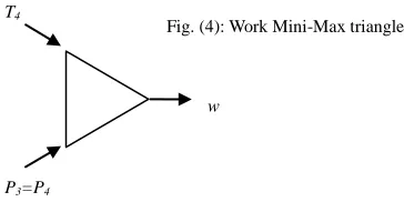
According to Bejan [86], for a system such as defined by the system states 1-2-3-4-5-1, in Fig. 1, a property of the system in this instance, W, and defined by the specific work, w, of (37.1e) reaches the minimum or maximum, when two other properties are held fixed or constant, as in this instance, the constant predetermined maximum pressure, and calculated ―fixed‖ maximum temperature. Bejan [86] notes that the three properties form a triangle. In this paper this is called work Mini-Max triangle as illustrated by Fig. (4):
In real engines, processes and reactions such as fuel injection and preparation, the increase or decrease of state point variables are time and rate dependent, with all cycle events of significance occurring in finite times and dependent on finite rates. Added to that are the choice of engine materials, materials properties limits and the accompanying consequent costs in using higher material grades. Thus, such set limits constraints, will often lead the engine designer to find optimal operating conditions. In the seminal work of Andresen, Salamon, and Berry in 1984 - ―Thermodynamics in Finite Time‖ [87], they refer to such search for optimal conditions as: search for ―Criteria of Merit‖; and a question of finding realistic limits to improve performance of real processes [87]. See also Andresen [88] and Hoffmann [89]. The methods have been successfully applied by Chen et al. [90], Ust et al. [91], Atmaca et al. [85], Asghari et al. [61], Rashidi et al. [51], Ebrahimi [40], [38] and others. The maximum temperature, T4, in the cycle, which is also the maximum combustion temperature, occurs at the predetermined maximum pressure, and by (37b), an increase in T4 will increase the work output, with T4 being dependent on the initial conditions. Thus, by (37.1e), too high or too low a specific work output can result in higher design (materials) and operating (fuel consumption, maintenance) costs [12]. The question that follows is: what is the optimal value of the combustion chamber temperature, T4, at (P3 = P4), that will maximise the fuel/air ratio at combustion, maximise the work output (the objective function) at high cycle efficiency, and hence, the power produced? High efficiency might mean using more expensive fuel and, hence, incurring high cost per rated power output; however, of concern is fuel economy – reasonable quantity fuel delivered that maximises the power output. From (36b), higher, T4, value will reduce the cycle efficiency! By the triangle principle of Bejan [86] – Fig. (4), and in relation to this effort, and the question posed, the peak maximum pressure, (P3=P4), is thus related to the power output, as shown by (37e). In this application, a key criterion of
w T4
P3=P4
By the triangle mini-max principle, dw≤0, at constant T4; (P3=P4)
Fig. (4): Work Mini-Max triangle
k
E P k
C P
E P v
net m C T kr r r r r r
W 1 1
.
1 1
13 merit is the pressure ratio; thus, by considering optimum
pressure ratio at maximum work, the ‗Equation of Operation‘, in the form of (37e) is differentiated with respect to the pressure ratio, rP, and set to zero in line with extreme event variational condition, i.e.:
1
21
2 T r 0 T r T
T dr
dW k
E k
E P
(37f)
Or
1 2
T T
rEk (37g)
The remodeled maximum temperature, T4, after substituting for, rE, by the relation of (19) is:
k k
T T T T
1
3 1 2
4
(37i)
The compression ratio for optimum pressure ratio and maximum work and hence, maximum power delivery is then,
1
3 4
k k
C
T T
r (37h)
The choice for maximum work criterion is backed by Andresen et al. [87] note, that, with such maximum power attainment and stability, comes, a price to pay for reduced efficiency, stating the observations of Curzon and Ahlborn, that, typical power producing units operate closer to the point of maximum power than at maximum efficiency. But, can the same results be obtained if the consideration was attaining maximum efficiency at cut-off? How then can the Maximum Work, and hence, maximum power output be attained? What are the control measures for, and path, to achieving maximum power? Will such measurable(s) be controllable for achieving fuel economy and meeting emissions regulations requirements?
3.2.6. Volumetric Efficiency
Volumetric efficiency, as applied in the program is defined as the ratio of the actual volume drawn of the charge at suction reduced to standard temperature and pressure, S.T.P, to the Engine Displacement or Swept volume.
(38)
3.3 Engine Performance Analysis Models
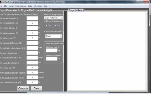
The efficient complete conversion of chemical fuel energy into useful mechanical work determines Engine performance [13]. The GUI for the engine performance analysis is shown in Fig. (5):
Fig. 5. DFA for engine performance analysis.
The required performance equations are:
(i.) Power ifo
IP ,BP ,FP
(39)Where, ifo = ―in form of‖
000 , 60 2
_ Q
NT BP
Power Brake
(39a)
BP IP FP Power
Friction _ (39b)
(ii.) Load
W ,MEP ,F,N,TQ
(40)Force on the piston:
(40a)
Where, (40.1a)
Work done by the engine:
MEP
vdW (40b)
Mean Effective Pressure:
P P P P P V V V V V V k
MEP 1, 2, 3, 4, 5, 1, 2, 3, 4, 5, s, (40c)
Or
P r r k
MEP 1, C, E, (40.1c)
Where, Ф, indicates a functional.
Also
Volume Swept
Done Work
MEP
(40d)
Note that MEP is expressed as, based on shaft work (Brake Mean Effective Pressure -BMEP), and on indicated or total power (Indicated Mean Effective Pressure-IMEP). The importance of the two ratios: IMEP/P3 and IMEP/P1 is taken into consideration in determining the maximum pressure, P3. In predicting real engines performance, available MEP values, in manufacturers‘ catalogue often published as BMEP, and Volume
Swept
P T S at e ch of volume