AVOID SYNCHRONIZATION LATENCY USING VLSI
IMPLEMENTATION
R.Keerthiga
1, T. M. Senthil Ganesan
2 1PG Scholar, Department of VLSI Design,
2Assistant Professor
Theni Kammavar Sangam College of Technology, Tamilnadu, (India)
ABSTRACT
The phenomenon of metastability is inherent in clocked digital logic. Many techniques have been presented for
minimizing metastability, both for crossing clock domains, and for handling asynchronous inputs. Flip-flops are
among these systems and can take an unbounded amount of time to decide which logic state to settle to once
they become metastable. This problematic behavior is often prevented by placing the setup and hold time
conditions on the flip-flop’s input. However, in applications they induce catastrophic failures. These events are
fundamentally impossible to prevent but their probability can be significantly reduced by employing
synchronizer circuits. The latter grant flip-flop longer decision time at the expense of introducing latency in
processing the synchronized input. The main contributions include two novel solutions for the problem of
synchronization. Speculation technique is the main theme that helps reducing synchronization latency.
Keywords: Metastability, Setup Time, Hold Time, Synchronization, Latency
I. INTRODUCTION
Metastability is a phenomenon that can cause system failure in digital devices, including FPGAs, when a signal
is transferred between circuitry in unrelated or asynchronous clock domains. This paper describes metastability
in FPGAs, explains why the phenomenon occurs, and discusses how it can cause design failures. The calculated
mean time between failures (MTBF) due to metastability indicates whether designers should take steps to reduce
the chance of such failures. This paper explains how System reliability can be improved by reducing the chance
of metastability failures with design techniques and optimizations.
II. METASTABILITY
The purpose of enforcing the setup and hold time conditions on combinational paths is to constrain the input of
every flip-flop: to ensure that it is held stable for at least tsu seconds before the clock edge and that it remains
stable for no less than th seconds afterwards. By doing so, flip-flop outputs are guaranteed to behave in a
pre-determined manner: they transition to the logic level of the input monotonically, with a nominal transition time
and within a nominal clock-to-q delay. These properties are essential for the design of deterministic
synchronous systems.
In some applications, however, the setup and hold times of a flip-flop’s input cannot be always satisfied. For
example, when the flip-flop is used to sample a real-time signal, input transitions can occur at any time relative
to the clock edge. For a clock edge occurring at tclk, if a transition occurs after tclk-tsu and before tclk + th (this
described above. In other words, it may transition or not transition at all, it may transition after a long delay with
a longer rise/fall time or it may produce multiple output transitions (behave non-monotonically).
Historically, flip-flops were not known to behave in this manner in the early days following their invention. It
was believed that a flip-flop whose setup and hold time conditions were violated will either succeed or fail to
capture the logic value of the input. The impact of these violations on the delay, transition time and
monotonicity of the flip-flop output had not been foreseen. In consequence, multiple early synchronous
computers which have included unconstrained flip-flops exhibited mysterious failures whose root cause was not
identified until the first mathematical analysis of the problem was published in 1952. The anomalous behavior
of unconstrained flip-flops was attributed to metastability: a pseudo-stable state in which a bistable element is
neither logic high nor low but somewhere in between.
The duration of the metastable condition is a probabilistic phenomenon, and therefore there is no guaranteed
maximum time. One can't build a bistable device such as a flip-flop that cannot go metastable. Metastability can
appear as a flip-flop that switches late or doesn’t switch at all. It can present a brief pulse at a flip-flop output
(called a runt pulse) or cause flip-flop output oscillations. Any of these conditions can cause system failures.
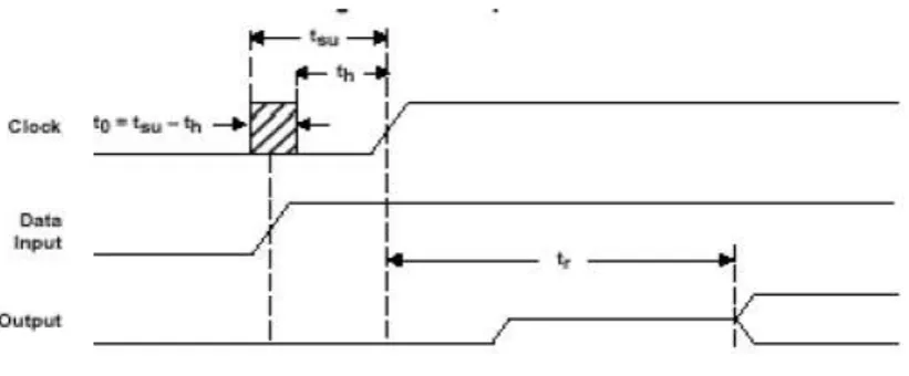
For a simple CMOS latch, valid data must be present on the input for a specified period of time before the clock
signal arrives (setup time) and must remain valid for a specified period of time after the clock transition (hold
time) to assure that the output functions predictably. This leaves a small window of time with respect to the
clock (t 0) during which the data is not allowed to change. If a data edge occurs within this aperture, the output
may go to an intermediate level and remain there for an indefinite amount of time before resolving itself either
high or low.
Fig. 2.1 Metastability Trigger
This metastable event can cause a failure only if the output has not resolved itself by the time that it must be
valid for use (for example, as an input to another stage); therefore, the amount of resolve time allowed a device
plays a large role in calculating its failure rate. Whenever there is any such violation, the output voltage is
anywhere between a logic high and a logic zero. In such a condition the flip-flop takes additional time to settle
to a stable output. And this stable output depends upon the process technology, manufacture and environment
conditions that may force the output to go to a particular value. There is no way that the final state can be
predicted.
This operation is analogous to a ball rolling over a hill. Each side of the hill represents a stable state, and the top
illustrated hill to roll down one side or the other, thermal and induced noise will jostle the state of the flip-flop
causing it to move from the quasi-stable state into either the logic 0 or logic 1state. Hence, the output is random.
In any case the CP-Q delay of the f/f is increased. The extra delay may be ten or twenty times longer than the
normal Clk-Q delay. This extra time is called the metastable resolution time. However, metastability may not
always result in unpredictable output. If provided sufficient time with proper excitation, the frequency to
frequency can in fact settle to a stable state.
Metastable events are associated with data transitions occurring close to the active edge of the clock. Because a
timing violation has occurred, the flip-flop will exhibit erratic behavior. The erratic behavior manifests itself in
the form of an extended propagation delay with an unpredictable resolution of the Q output (of f/f). This
metastable event can cause a failure only if the output has not resolved itself by the time that it must be valid for
use therefore, the amount of resolve time allowed for a device plays a large role in calculating its failure rate.
2.1 Scenarios of Metastability Occurance
Whenever setup and hold violation time occurs, metastability occurs, so it is to be seen when this signal violates
this timing requirement.
When the input signal is an asynchronous signal.
When the clock skew is more (rise time and fall time is more than the tolerable Values).
When interfacing two domains operating at two different frequency.
When the combinational delay is such way that, it changes flip-flop’s input in the required window (setup +
hold window)
2.2 Metastability Measurement
In order to define the metastability characteristics of a device, 3 things must be known
Possible sequence that the device will enter a metastable state
Period of device remain in that state
Measured propagation delay of the device.
2.3 Methods to Avoid Metastability
Synchronize any asynchronous input through one path that has at least one and preferably two flip-flops in
series.
The flip-flops should be running on the same edge of your system clock as the rest of the circuit. This will
limit the area of potential problems to one path instead of several.
Use buffered flip-flops, or un-buffered flip-flops with minimum load.
Ensure that setup time of the destination flip-flop is met. This will avoid the creation of metastable
conditions inside the circuit and minimize the propagation of any should they occur
Use metastability hardened Flip-flops.
III. METHOS TO AVOID SYNCHRONIZATION LATENCY
3.1 SPECULATION
An alternative strategy to mitigate synchronization latency is to use redundant hardware to perform speculative
equivalent number of computation cycles. If computing an output based on an asynchronous input requires n
synchronization cycles and m computation cycles, this method yields a processing time of max(m, n) cycles as
opposed to m + n for conventional synchronization. This reduces the total latency to tb + T _ max(m, n) where
tb is the bundling delay. Metastable states occur relatively rarely compared to handshake requests and that
incurring two cycles to synchronize each individual handshake is thus unwarranted. Their scheme involves
using a single flip-flop k as a synchronizer and speculating that it does not become metastable. A detector circuit
can then reliably identify, n cycles later, whether k has actually become metastable. If this was the case, each
register in the synchronous block is restored to a backup copy which is kept in an n-level stack. Using this form
of speculation, the latency of processing the asynchronous request is reduced to a single cycle only (plus tb).
The cost is that each register needs to be duplicated n times.
3.1.1 Advantages
Approach is entirely architectural and does not target the synchronization process itself.
It does not rely on any assumptions about the relationship between the communicating clocks.
It does not require fast metastability-resolving flip-flops.
Trading reliability and low-latency with duplicated hardware will be an increasingly-affordable option in
future technologies because of the continuous growth of available design area
3.2 Datapath Unfolding
Speculation is the use of either time or resource redundancy to perform potentially useful work. Modern digital
systems employ speculation at different abstraction levels. For example, memory management speculatively
populates cache hierarchies with pre-fetched data to reduce the impact of slow memory access on processing
speed. Also, processors that use branch prediction execute the instructions following branches speculatively to
increase throughput. This is because restoring the state of a pipeline in the case of un-speculation is trivial. For
example, when a branch condition in a pipelined processor is evaluated, invalid instructions in the fetch and
decode stages can be discarded by flushing these stages. On the other hand, speculative computations cannot be
“reversed” in a similarly straight-forward manner in non-pipelined systems. This is because non-pipelined
systems have loop dependencies (i.e. feedback paths) such as the one represented by the expression x + 1. The
existence of loop dependencies can corrupt the system state in the case of un-speculation (pipelined systems are
free from such dependencies by definition). Nevertheless, arbitrary designs can be converted into functionally
equivalent pipelines by unfolding. Although pipelining a design by unfolding is used primarily to increase
throughput, it can also be used to perform speculative computations during synchronization cycles. To
demonstrate how, consider the generic synchronous module. The module is represented by a Moore machine
consisting of the state register R, the combinational block C and the asynchronous port [req, d, ack]. To
maintain reliability, two flip-flops are added to synchronize req. The latency introduced by this chain can be
“hidden” by speculatively computing what the machine state would have been if req changed two cycles earlier.
IV. PROPOSED METHOD
4.1 Sequenced Latching
A novel technique to latch data reliably during synchronization cycles is the technique of Sequenced Latching.
In short, a synchronizer is used as a state machine to sequence a series of latching operations. The synchronizer
is constrained such that its state does not change when a latching operation fails. Therefore, any failed latching
V. COMPARISON OF SPECULATIVE TECHNIQUES
In Speculative Synchronization, method uses a single flip-flop k to synchronize the asynchronous handshake
and a detector to reliably identify. When a metastable state is identified, the machine is restored to a previous
correct state. This approach can be summarized as “assume, execute, verify then correct if necessary”.
In Data path unfolding, additional instances of the entire machine are used to speculatively compute the machine
states following the arrival of data. The assumption used here is that the value of the asynchronous data bus was
valid n cycles earlier. This approach can be summarized as “assume, verify then execute”.
In Sequenced Latching, unlike the other two speculative methods, sequenced latching makes an individual
assumption on each synchronization cycle. The assumption is that the transition of the synchronizer flip-flop Si
is captured by its successor Si+1. The delays between the synchronizer flip-flops and the sequenced pipeline
stages are constrained such that data moves through the pipeline safely when this assumption holds.
VI. CONCLUSION
The growing number of asynchronously-clocked cores in modern systems means that the negative performance
impact of clock domain crossing latency is likely to increase. Two novel architectural solutions (data path
unfolding and sequenced latching) that are free from these limitation are proposed. The proposed methods
leverage hardware duplication to speculatively compute the first few system states following a change in the
asynchronous input. This allows a system to hide synchronization latency by overlapping it with the
computation of the first few data-dependent states. The simulation results shows that metastability occurrence
can be detected and based on the count the occurrence can be reduced which helps in reducing synchronization
latency. The future work can be extended to work on the clock domain interface performing adaptive
synchronization.
REFERENCES
[1]. Baghini, M., and Desai, M., “Impact of technology scaling on metastability performance of CMOS
synchronizing latches,” in Proc. 7th Asia South Pacific, 15th Int. Conf. VLSI Design. Proc., Design
[2]. Chakraborty, A., and Greenstreet, M., “Efficient self-timed interfaces for crossing clock domains,” in
Proc. 9th Int. Symp. Asynchron. Circuits Syst., May 2003, pp. 78–88.
[3]. Chaney, T. J., and Molnar, C. E., “Anomalous behavior of synchronizer and arbiter circuits,” IEEE Trans.
Comput., vol. 22, no. 4, pp. 421–422, Apr. 1973.
[4]. Dally, W., and Tell, S., “The even/odd synchronizer: A fast, all-digital, periodic synchronizer,” in Proc.
IEEE Symp. Asynchron. Circuits Syst., May 2010, pp. 75–84
[5]. Ginosar, R., “Metastability and synchronizers: A tutorial,” IEEE Design Test Comput., vol. 28, no. 5, pp.
23–35, Sep.–Oct. 2011.
[6]. Greenstreet, M., “Implementing a stair chip,” in Proc. IEEE Int. Conf. Comput. Design, VLSI Comput.
Process, Oct. 1995, pp. 38–43.
[7]. Jones, I. W., Yang, S., and Greenstreet, M., “Synchronizer behavior and analysis,” in Proc. 15th IEEE
Symp. Asynchron. Circuits Syst., May 2009, pp. 117–126.
[8]. Kessels, J., Peeters, A., Wielage, P., and Kim, S.-J., “Clock synchronization through handshake signaling,”
in Proc. 8th Int. Symp. Asynchron. Circuits Syst., Apr. 2002, pp. 59–68.
[9]. Kinniment, D., Bystrov, A., and Yakovlev, A., “Synchronization circuit performance,” IEEE J. Solid-State
Circuits, vol. 37, no. 2, pp. 202–209,Feb. 2002.
[10]. Sarmenta, L., Pratt, G., and Ward, S., “Rational clocking [digital systems design],” in Proc. IEEE Int.
Conf. Comput. Design, VLSI Comput. Process., Oct. 1995, pp. 271–278.
[11]. Yang, S., Jones, I., and Greenstreet, M., “Synchronizer performance in deep sub-micron technology,” in
Proc. 17th IEEE Int. Symp. Asynchron. Circuits Syst., Apr. 2011, pp. 33–42.
[12]. Yun, K., and Dooply, A., “Pausible clocking-based heterogeneous systems,” IEEE Trans. Very Large
Scale Integr. (VLSI) Syst., vol. 7, no. 4, pp. 482–488, Dec. 1999.
[13]. Zhou, J., Ashouei, M., Kinniment, D., Huisken, J., and Russell, G., “Extending synchronization from
super-threshold to sub-threshold region,” in Proc. IEEE Symp. Asynchron. Circuits Syst., May 2010, pp.
85–93.
[14]. Zhou, J., Kinniment, D., Russell, G., and Yakovlev, A., “Adapting synchronizers to the effects of on chip
variability,” in Proc. 14th IEEE Int. Symp. Asynchron. Circuits Syst., Apr. 2008, pp. 39–47.
[15]. Zhou, J., Kinniment, D., Russell, G., and Yakovlev, A., “A robust synchronizer,” in Proc. IEEE Comput.
Soc. Annu. Symp. Emerg. VLSI Technol. Archit., Mar. 2006, pp. 442–443.
BIOGRAPHICAL NOTES
MS.R.KEERTHIGA is presently pursuing M.E final year in Electronics and Communication Engineering
Department (specialization in VLSI design) from Theni Kammavar Sangam College of Technology, Theni,
Tamilnadu, India.
Mr.T.M.SENTHIL GANESAN is working as a Assistant Professor in Electronics and Communication