311 |
P a g e
MITIGATION AND ANALYSIS OF VERY FAST
TRANSIENT
OVER
VOLTAGES(VFTOS)
OF
TRANSFORMER
IN
765KV
GAS
INSULATED
SUBSTATION (GIS) USING WAVELET TRANSFORM
K.Prakasam
1, Prof. M. Surya Kalavathi
2, D.Prabhavathi
31
Department of EEE, JNTUCEA, JNTUA, (India)
2
Department of EEE, JNTUHCEH, (India)
3
Department of EEE, JNTUCEA, JNTUA, (India)
ABSTRACT
Mitigation and analysis of very fast transient over voltages (VFTO) is very important in gas insulated substations
(GIS) .In this paper a power transformer rating of 400MVA in 765kV/400kV gas insulated substation has been
considered and different techniques for mitigation and analysis of very fast transient over voltages (VFTOs) at the
transformer are applied and the same results are analyzed by the application of discrete wavelet transform (DWT) as
wavelet transform gives the accurate results. The proposed system has been designed with Mat Lab software
platform and the system is simulated to evaluate the peak values of VFTOs generated at the both at transformer and
open end with and without damping methods (Ferrite ring and nono crystalline). The results show that the peak
value of VFTOs can be considerably reduced by introducing the above damping methods. The outcomes are
explored to wavelet transform for transient information. By the application of wavelet transform it has concluded
that an exact measurement VFTOs can be obtained
Keywords: Damping, Ferrite, Peak, Transient, Surges, Wavelet.
I. INTRODUCTION
During switching operation of disconnecting switches in gas insulated substations number of re strikes and pre
strikes occurs and due to which voltage collapses with in very short duration (nanoseconds) at switching gap. The
travelling surges generated by the switching operations travel either direction of the system. The super imposition of
these reflected waves cusses rise of voltage which is known as very fast transient over voltages(VFTOs).The VFTO
in GIS are greater concern if GIs is operating at higher voltage level. The major problems associated with the very
fast transient over voltages (VFTOs) generated in GIS causes , Flash over to ground at the disconnecting switch
312 |
P a g e
VFTOs, Di-electric strength is reduced under VFTOs, if non-uniform electric field is formed by the particles(primarily metallic), effect on equipments such as bushing, power transformer and instrument transformers,
Transient Enclosure Voltage (TEV) on external surface of the sheath. This may cause flashovers to nearby grounded
objects. Which necessitates suppressing the magnitude of VFTOs?
II. MITIGATION AND ANALYSIS OF VFTOS
The new approaches are presented in this paper. A matched ferrite ring, nanocrystalline and RF resonator formed by
shielding inside the GIS. The very fast transient over voltages (VFTOs) in the proposed system has been studied
well and the most suitable methods (ferrite ring and nanocrystalline) have been chosen for mitigation of VFTOs and
are presented in the following section. The parameters of proposed system have been estimated based on very fast
transient nature. The surge impedance (Z0), velocity of propagation (υ) and formative time (τ) can be evaluated from
the following equations.
As per the literature survey it has been observed that, the VFTOs can damp to a great considerable level of peak
using ferrite rings. The most of the authors tested the ferrite ring under low voltage and low frequency and
conventional comparison given between the shunt resistor and ferrite ring, this paper introduced a new method of
analysis of very fast transient over voltages VFTOs which is known as wavelet transform as the VFTOs are concern
to high frequency transients. The comparable circuit of ferrite ring is shown in the following figure3.
Fig.1.Equivalent circuit of ferrite ring
Most of the authors tested the ferrite ring under low voltage and low frequency and conventional comparison given
313 |
P a g e
gets saturation. Since the nanocrystalline exhibits enhanced electrical property in the high frequency range (100KHz to 3MHz) and have high Dielectric strength. The nanocrystalline is modeled as R, L connected in series and
connected in parallel with capacitor. The parameters of R= 150Ω, L=0.002mH and C = 0.001nF chosen in the
design of nanocrystalline. The equivalent circuit of nanocrystalline is shown in the following figye4.
Fig.2.Equivalent circuit nanocrystalline
The RF resonator is a high frequency radio frequency device tuned to a dominant harmonic frequency. The RF
resonator can be electrically treated as LC circuit tuned to high frequency and low quality factor. The estimated peak
magnitudes of VFTOs with RF resonator have been produced in the next section. From the outcomes of the
proposed system it has been cleared that the peak magnitude of VFTOs can be considerably reduced.
2.1 Modelling of Proposed system
The simulation model of proposed system has been done using mat lab platform. The parameters of the system are
estimated based on very fast transient nature (VFT).
58
58
OHT L
80pF 765kV/400kV GIS Si mul ati on Model
Discre te , Ts = 5e -005 s.
powe rgui v + -Voltage Measurement2 v + -Voltage Measurement1 v + -Voltage Measurement Vcb T o Workspace2 Vtr
T o Workspace1
vds T o Workspace
Scope2 Scope1 Scope -K-Gai n1 -K-Gai n Conn1 Conn2 DS
DC Voltage Source
80pF1
80pF 51
4nF1 4nF
242 120nf8 120nf9
120nf7 120nf6 120nf52 120nf50 120nf49 120nf48 120nf47 120nf46 120nf45 120nf44 120nf43 120nf42 120nf41 120nf40 120nf4 120nf39 120nf38 120nf37 120nf36 120nf35 120nf34 120nf33 120nf32 120nf31 120nf30 120nf3 120nf29 120nf28 120nf27 120nf26 120nf25 120nf24 120nf23 120nf22 120nf21 120nf20 120nf19 120nf18 120nf17 120nf16 120nf14 120nf13 120nf12 120nf11 120nf10 120nf1
314 |
P a g e
III. SIMULATION TEST RESULTS
The simulation test has been carried at transformer and at open end to estimate the magnitude of very fast transient
over voltages (VFTOs) and rise time. The simulation outcomes of the proposed system have been presented in this
section.
Fig.4.VFTO at Transformer under no damping
Fig 4 represents the VFTO at the transformer under no damping conditions. From the figure 4 it can be observed that
the peak magnitude of VFTO is 2.09p.u and the rise time is 48ns
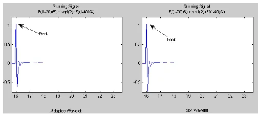
Fig.5.VFTO at Transformer with wavelet transforms (Db4)
Fig 5 represents the VFTO at the transformer under no damping conditions estimated with wavelet transform (Db4).
From the figure 5 it can be observed that the peak magnitude of VFTO is 2.02p.u.
0 50 100 150 200 250
-2 -1.5 -1 -0.5 0 0.5 1 1.5
Time in (ns)
M
ag
nit
ud
e
of
V
olt
ag
e
in
p.
u
VFTO at Transformer (Vtr) with Ferrite ring
Peak
Fig.6.VFTO at Transformer with ferrite ring
Fig 6 represents the VFTO at the transformer with ferrite ring. From the figure 6 it can be observed that the peak
315 |
P a g e
Fig.7.VFTO at Transformer with ferrite ring
Fig 7 represents the VFTO at the transformer with ferrite ring with wavelet transform (Db4). From the figure7 it can
be observed that the peak magnitude of VFTO is 1.38p.u.
0 50 100 150 200 250
-1.5 -1 -0.5 0 0.5 1 1.5
Time in (ns)
M
ag
ni
tu
de
o
f V
ol
ta
ge
in
p
.u
VFTO at Transformer (Vtr) with Nanocrystalline
Peak
Fig.8.VFTO at Transformer under no damping
Fig 8 represents the VFTO at the transformer under with ferrite ring. From the figure 8 it can be observed that the
peak magnitude of VFTO is 1.18p.u and the rise time is 32ns
Fig.9.VFTO at Transformer under no damping
Fig 9 represents the VFTO at the transformer with ferrite ring with wavelet transform (Db4). From the figure it can
316 |
P a g e
0 50 100 150 200 250
-2 -1 0 1 2
Peak
Fig.10.VFTO at open end under no damping
Fig 10 represents the VFTO at the transformer under no damping. From the figure it can be observed that the peak
magnitude of VFTO is 1.81p.u and the rise time is very more.
Fig.10.VFTO at open end under no damping
Fig 10 represents the VFTO at the transformer under with ferrite ring. From the figure 10 it can be observed that the
peak magnitude of VFTO is 1.81p.u and the rise time is very more.
0 50 100 150 200 250
-1.5 -1 -0.5 0 0.5 1 1.5
Time in (ns)
M
ag
ni
tu
de
o
f V
ol
ta
ge
in
p
.u
VFTO at Openend (Voc) with Ferrite ring
Peak
Fig.11.VFTO at open end with ferrite ring
Fig 11 represents the VFTO at open end with ferrite ring. From the figure 11 it can be observed that the peak
317 |
P a g e
Fig.12VFTO at open end with ferrite ring
Fig 12 represents the VFTO at open end with ferrite ring with wavelet transform (Db4). From the figure12 it can be
observed that the peak magnitude of VFTO is 1.25p.u.
0 50 100 150 200 250
-2 -1.5 -1 -0.5 0 0.5 1 1.5
Time in (ns)
M
ag
ni
tu
de
o
f V
ol
ta
ge
in
p
.u
VFTO at Open end (Voc) with Nanocrystalline
Peak
Fig.13.VFTO at open end with ferrite ring
Fig 13 represents the VFTO at open end with nanocrystalline. From the figure 13 it can be observed that the peak
magnitude of VFTO is 1.27p.u and the rise time is >200ns.
Fig.14.VFTO at open end with ferrite ring
Fig 14 represents the VFTO at open end with nanocrystalline. From the figure 14 it can be observed that the peak
318 |
P a g e
0 50 100 150 200 250
-0.8 -0.6 -0.4 -0.2 0 0.2 0.4 0.6 0.8 1 1.2
Time in (ns)
M ag ni tu de o f V ol ta ge in p .u
VFTO at Transformer with RF Resonator
Peak
Fig.15.VFTO at transformer with RF resonator
Fig 15 represents the VFTO at transformer with RF resonator. From the figure 15 it can be observed that the peak
magnitude of VFTO is 1.02p.uand rise time is 18ns.
Fig.16.VFTO at transformer with RF resonator
Fig 16 represents the VFTO at transformer with RF resonator with wavelet transform (Db4). From the figure 16 it
can be observed that the peak magnitude of VFTO is 1.02p.uand rise time is 16.7ns.
0 50 100 150 200 250
-3 -2.5 -2 -1.5 -1 -0.5 0 0.5 1 1.5
Time in (ns)
M ag ni tu de o f V ol ta ge in p .u
VFTO at Open end (Voc) with RF Resonator
Peak
Fig.17.VFTO at open end with RF resonator
Fig 17 represents the VFTO at open end with RF resonator. From the figure 17 it can be observed that the peak
319 |
P a g e
Fig.18.VFTO at open end with RF resonator
Fig 18 represents the VFTO at open end with RF resonator. From the figure 18 it can be observed that the peak
magnitude of VFTO is 1.02p.uand rise time is 16.7ns.
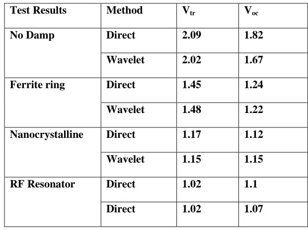
TABLE 1 PEAK MAGNITUDE OF VFTO IN P.U
Test Results
Method
V
trV
ocNo Damp
Direct
2.09
1.82
Wavelet
2.02
1.67
Ferrite ring
Direct
1.45
1.24
Wavelet
1.48
1.22
Nanocrystalline
Direct
1.17
1.12
Wavelet
1.15
1.15
RF Resonator
Direct
1.02
1.1
Direct
1.02
1.07
IV. CONCLUSIONS
320 |
P a g e
By employing the ferrite ring, the peak magnitude of VFTO at transformer has been reduced by 30.62%
and with nanocrystalline it has been reduced by 46.55% as well as with RF resonator the peak magnitude
reduced by 51.12%. In the second stage of research work the peak magnitude of VFTO at open end has
been reduced by 32.97% and with nanocrystalline it has been reduced by 39.45% similarly with RF
resonator it has been reduced by 42.16%.
In the proposed system the percentage of reduction has been analyzed with reference to no damping
conditions. However the accurate estimation of peak magnitudes of VFTOs has been achieved by the
application of wavelet transform (Db4).
ACKNOWLEDGMENT
Acknowledgments I would like to express my gratitude to Dr.M Surya Kalavathi, madam garu who has
encouraged me to pursue this work and taught me the “art of „Analysis and Mitigation methods Very Fast
Transients over Voltages (VFTOs) in gas insulated substations‟ and „Applications of Wavelet Transform
in Electrical Engineering‟ is my pleasure to acknowledge role of my co author D.Prabhavathi in
completion of this work.
REFERENCES
[1] Bi.Tiechen, and Lu.,Zhang, “Calculation of Very Fast Transient Overvoltage in GIS”, IEEE/PES Conference on
Transmission and Distribution, 2005,Vol.4..
[2] Kamakshaiah., “Simulation and measurement of very fast transient over voltages in a 245kv gis and research
on suppressing method using ferrite rings” ARPN Journal of Engineering and Applied Sciences, vol. 5, No. 5,
2010,88- 95.
[3] V.Vinod Kumar, Joy .M.Thomas and M.S. Naidu, “VFTO Computation in a 420kV GIS”, Eleventh
International Symposium on High Voltage Engineering, (Conf. Publ. No. 467), 1999,pp. 319-32.
[4] S.A. Boggs, F.Y.Chu and N. Fujimoto „Disconnect Switch Induced Transients and Trapped charge in GIS‟,
IEEE Transactions on Power Apparatus and Systems, Vol. PAS-101, 1998,pp. 3593-3596.
[5] Y. Shibuya, S. Fuji, and N. Hosokawa, “ Analysis of very fast transient over voltage in transformer winding”,
IEE Proc. Generation transmission and distribution, Vol.144, No.5,1997, pp461-46.
[6] H. Nobuhiro Shimoda,. I.,Murase, and H.Oshima ,Aoyagi, I. ,Miwa, "Measurement of transient voltages
induced by disconnect switch operation", IEEE Transactions on Power Apparatus and Systems,
321 |
P a g e
[7] J.A.P.Martinezm R. Iravani, A. Keri and D. Povh1” Modeling guidelines for very fast transients in GasInsulated substations”, IEEE working group modeling and analysis of system transients, Vol.11, no.4, 1998, pp,
2028-2047.
[8] N. Hosokawa, „Very fast Transient Phenomena associated with Gas Insulated Substations‟, CIGRE, 1996, pp.
33-13, .
[9] S.Cariimavoid and R. Mahmutdehajid, “More accurate modeling of Gas insulated components in digital
simulations of very fast transients”, IEEE Transactions on Power delivery, Vol.7, NO.1, pp. 434-441, 1963.
[10]R. Witzman „Fast Transients in Gas Insulated substations – Modeling of Different GIS components‟, Fifth ISH,
Braunschweig,. WorkingGroup33. Pp.13-09, „Very Fast Transient Phenomenon Associated With GIS, CIGRE,
1998.
[11]U.Riechert, Krüsi and D. Sologuren-Sanchez, “Very Fast Transient Overvoltage‟s during Switching of
Bus-Charging Currents by 1100 kV Disconnector”, CIGRÉ Report A3-107, 43rd CIGRÉ Session, 2010,pp.22-27.
[12]S.Burow, U. Riechert, W. Köhler and S. Tenbohlen, “New mitigation methods for transient overvoltages in gas
insulated substations”2013,.
[13] A.J Martinez. “Statistics Assessment of Very Fast Transient Overvoltages in Gas Insulated Substations”. IEEE