40
Analysis of Efficient Architectures for FIR Filters using
Common Subexpression Elimination Algorithm
M. Thenmozhi, N. Kirthika
Abstract -Finite Impulse Response (FIR) filters are widely applied in multistandard wireless communications. The two key requirements of FIR filters are reconfigurability and low complexity. In this paper, two reconfigurable FIR filter architectures are proposed, namely Constant Shift Method [CSM] and Programmable Shift Method [PSM]. The complexity of linear phase FIR filters is dominated by the number of adders (subtractors) in the coefficient multiplier. The Common Subexpression Elimination (CSE) algorithm reduces number of adders in the multipliers and dynamically reconfigurable filters can be efficiently implemented. A new greedy CSE algorithm based on Canonic Signed Digit (CSD) representation of coefficients multipliers for implementing low complexity higher order FIR filters. Design examples shows that the filter architectures offer power reduction and good area and speed impr ovement over the existing FIR filter implementation.
Keywords- Software Defined Radio (SDR), channelizer, FIR filter, common subexpression elimination.
————————————————————
I INTRODUCTION
Recent advances in mobile computing and communication applications demand low power and high speed VLSI Digital Signal Processing (DSP) systems. One of the most important operations in DSP is finite impulse response filtering. The FIR filter performs the weighted summations of input sequences and is widely used in mobile communication systems for variety of tasks such as channelization, channel equalization, pulse shaping and matched filtering due to their properties of linear phase and absolute stability. The digital filters employed in mobile systems must be higher order and realized to consume less power and operate at high speed. Recently evolving as a promising technology in the area of wireless communications is Software Defined Radio (SDR). The idea behind SDR is to replace most of the analog signal processing in the transceivers with digital signal processing in order to provide the advantage of flexibility through reconfiguration or reprogramming. This will support multistandard wireless communications in different air-interfaces to be implemented on a single hardware platform [2]. SDR receiver must be realizing of low power consumption and high speed. The most computationally demanding block of a SDR receiver is channelizer which operates at the highest sampling rate [3]. Channel filter which extracts multiple narrowband channels from a wideband signal using a bank of FIR filter. In polyphase filter structure, decimation can be done to channel filtering so that need to operate only low sampling rates. The speed of operation of the channel filter is reduced by using polyphase filter structure [4]. The aim of the wireless communication receiver is to realize its applications in mobile, low area and low power is possible by implementation of FIR channel filter.
Channelizer requires high speed, low power and reconfigurable FIR filters. The problem of designing FIR filters is dominated by a large number of multiplications, which increases area and power even if implemented in full custom integrated circuits [5]. The multiplications are reduced by replacing them into addition, subtraction and shifting operation. The main complexity of FIR filters is dominated by the number of adders/subtractors used to implement the coefficient multipliers. To reduce the complexity, the coefficient can be expressed in common subexpression elimination methods based on Canonical Signed Digit (CSD) representation to minimize the number of adders/subtractors required in each coefficient multiplier. The aim of CSE algorithm is to identify multiple occurrences of identical bit patterns present in coefficients, to eliminate the redundant multiplications. The proposed CSE method which improved adder reductions and low complexity FIR
filter compared to the existing implementation. The
reconfigurability of FIR filter depends on Reconfigurable Multiplier Block (ReMB). The ReMB, which generate all the coefficient products and multiplexer which select the required coefficient depends on the inputs. This multiplexer used to reduce the redundancy in the multiplier block design [6]. In wireless communication application reconfigurable filters are meet adjacent channel attenuation specification. In this paper, to propose two architectures that integrates reconfigurability and low complexity. The architectures are Constant Shift Method (CSM) and Programmable Shifts Method (PSM) [7]. Multiplication of single variable (input signal) with multiple constants (coefficients) is known as Multiple Constant Multiplications (MCM) [8]. The MCM is optimized for eliminating redundancy using proposed CSE algorithm to minimize the complexity. This paper is organized as follows. The CSE method is reviewed in section II. The greedy common subexpression elimination algorithm is proposed in Section III. In Section IV, the proposed FIR filter architecture is introduced. Design results and comparison are shown in Section V. Section VI provides the conclusion.
2 COMMON SUBEXPRESSION ELIMINATION
A CSE algorithm using binary representation of coefficients for the implementation of higher order FIR filter with a fewer number of adders than CSD-based CSE methods is used. CSE method is more efficient in reducing the number of adders needed to realize the multipliers when the filter coefficients are represented in the binary form. The observation is that the number of unpaired bits (bits that do not form Common Subexpressions (CSs)) is considerably few for binary coefficients compared to CSD coefficients, particularly for
_______________________ M.Thenmozhi
PG Scholar-M.E. VLSI Design Sri Ramakrishna Engineering College
Coimbatore, Tamilnadu
[email protected] N.Kirthika
Assistant Professor-M.E. VLSI Design Sri Ramakrishna Engineering College
Coimbatore, Tamilnadu
41
higher order FIR filters. The Binary CSE (BCSE) algorithm deals with elimination of redundant binary common subexpression that occurs within the coefficients. The BCSE technique focuses on eliminating redundant computations in coefficient multipliers by reusing the most common binary bit patterns (BCSs) present in coefficients [9]. The number of BCSs that can be formed in an n-bit binary number is 2n − (n + 1).
For example, a 3-bit binary representation can form four BCSs, which are [0 1 1], [1 0 1], [1 1 0] and [1 1 1]. These BCSs can be expressed as
[0 1 1] = x2 = 2−1x + 2−2x (1)
[1 0 1] = x3 = x + 2 −2
x (2)
[1 1 0] = x4 = x + 2 −1
x (3)
[1 1 1] = x5 = x + 2−1x + 2−2x (4)
where x is the input signal. Note that other BCSs such as [0 0 1], [0 1 0] and [1 0 0] do not require any adder for implementation as they have only one nonzero bit. A straightforward realization of above BCSs would require five adders. However x2 can be obtained
from x4 by a right shift operation (without using any extra adders).
x2 = 2 −1
x + 2−2x = 2−1(x + 2−1x) = 2−1x4 (5)
Also, x5 can be obtained from x4 using an adder:
x5 = x + 2 −1
x + 2−2x = x4 + 2 −2
x. (6)
Thus, only three adders are needed to realize the BCSs x2 to x5. The
number of adders required for all the possible n-bit binary subexpressions is 2n−1 − 1. The number of adders needed to
implement the coefficient multipliers using the binary
representation-based BCSE is considerably less than the CSD-based CSE methods.
3
GREEDY
COMMON
SUBEXPRESSION
ELIMINATION ALGORITHM
The new CSE algorithm combines three techniques, binary Horizontal Subexpression Elimination (HCSE), binary Vertical Subexpression Elimination (VCSE) and hardwiring of the final stages, which reduces the number of adders. This technique focuses on eliminating redundancy by searching and selecting patterns with a look ahead technique in coefficient multiplier [10]. The previous methods only based on (BCSs), for example x3 to x6 are formed from the binary representation of coefficient as follows.
[0 1 1] = x3 = 2 −1
x1 + 2 −2
x1 (7)
[1 0 1] = x4 = x1 + 2 −2
x1 (8)
[1 1 0] = x5= x1 + 2−1 x1 (9)
[1 1 1] = x6 = x1 + 2 −1
x1+ 2 −2
x1 (10)
A direct realization of the BHCSs (7) to (10) would require 5 adders. But as x5 can be obtained from x3 by a shift operation and x6
from x5 using an adder, only 3 adders are required to realize the
BHCSs.
x3= 2 -1
x1+ 2 -2
x1 = 2 -1
( x1+ 2 -1
x1 ) = 2 -1
x8 (11)
x6 = x1 + 2 -1
x1 + 2 -2
x1 = x8 + 2 -2
x1 (12)
The main disadvantage of the BHCSs is formed without a look-ahead and therefore many bits are left ungrouped after obtaining the
BHCSs. The proposed CSE method can be explained using the example of a 12-tap FIR filter coefficients shown in Table I.
Table I Filter Coefficients representation of CSD
The patterns are obtained based on a look-ahead method, as shown in Table II and III. Table II shows the conventional horizontal subexpression formation for an example filter h0 and h1, whereas Table III shows the same fusing our look-ahead method. In Table II the two bits are ungrouped. Whereas in Table III all the bits are grouped this minimizes the number of adders. The HCSs x3= [1 0
1], x4 = [1 0 -1], x5 = [1 0 0 1],x6 = [1 0 0 -1] and VCS x2 = [1 1].
Table II Sequential Grouping (Horizontal Method)
Table III Look Ahead Method Grouping
Table IV formed by Table I by substituting HCSs, [1001] =5, [101] =3 and VCS [11] =2. Super-subexpression (SSs) is formed by identical shifts between them or an HCS and nonzero bits. In Table II, the SS 8 and SS 9 are formed. From the HCS [101] and the bit „1‟and „-1‟ with a shift difference of one between them. (as in h3 and h4 ).
Table IV Final Representation of FIR Filter Coefficient
From Table IV, the output of the example can be expressed as
yk =2- 3 x2 +2-5 x6 +2-10 x3 +2-5 x2[- 1]+ 2 -7 x6[ -1]+ 2- 10x3[- 2]+ 2- 4 x9[ -3]+ 2 -11x2[-3] +2- 4 x9[ -4] +2- 2 x5[ -5]+ 2- 7 x5[ -5](13)
42
solution in application of specific filters. In SDR receivers, the channel filter coefficients need to be changed as the filter specification. So, reconfigurability is needed for SDR channel filters. In next section two architectures are proposed that incorporates reconfigurability into the greedy CSE based low complexity filter architecture.
4 PROPOSED FIR FILTER ARCHITECTURES
In this section, the proposed FIR filter architecture is presented. Fig.1 shows proposed FIR filter architecture based on the transposed direct form. The dotted portion in Fig. 3 represents the Multiplier Block (MB) [coefficient multiplier share the same input].
Fig. 1 FIR Filter Architecture (Transposed direct form).
The MB reduces the complexity of the filter implementations, by exploiting MCM. The redundancy occurs in MCM, that redundant computations are eliminated using greedy CSE. In Fig. 1, PE-i represents the processing element corresponding to the ith coefficient. PE performs the coefficient multiplication operation with the help of a shift and add unit. The architecture of PE is different for proposed CSM and PSM. In the CSM, the filter coefficients are partitioned into fixed groups and hence the PE architecture involves constant shifters. But in the PSM, the PE consists of programmable shifters (PS). The FIR filter architecture can be realized in a serial way in which the same PE is used for generation of all partial products by convolving the coefficients with the input signal (x[n] *h) or in a parallel way, where parallel PE architectures are employed.
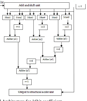
A. Architecture of Constant Shift Method
The CSM architecture is quite straight forward. The basic design in this approach is to store the coefficients directly in the LUT. These coefficients are divided into groups of 3-bits and are used as the select signal for the multiplexers. In this architecture the number of multiplexer units required is [n/3], wherenis the wordlength of the filter coefficients. For example, if the filter coefficients are 9-bit, then the number of multiplexers required is 3. This approach can be explained with the help of a 9-bit coefficient h= „0.111111111‟. This h is the worst-case 9-bit coefficient since all the bits are nonzero. Since n=9, the number of multiplexers required is 3. The coefficient his expressed as
y =2-1x+2-2x +2-3x +2-4x +2-5x +2-6x +2-7x +2-8x+2-9x (14) By partitioning equation (8), we obtain
h = 2-1 (x +2-1x+2-2x +2-3x +2-4x +2-5x +2-6x +2-7x+2-8x) (15)
h = 2-1 (x +2-1x+2-2x +2-3 (x +2-1x +2-2x) +2-6(x +2-1x+2-2x) (16)
Now the terms (x +2-1x +2-2x) and (x +2-1x) can be obtained from the shift and add unit. Then by using the 3 multiplexers, precisely using two 8:1 and one 4:1 (for the last two bits of the filter coefficients), the intermediate sums shown inside the brackets of (16) can be obtained. The final shifter unit will perform the shift
operations 2−1, 2−3 and 2−6. Since these shifts are always constant, programmable shifters are not required. The final adder unit will add all the intermediate sums to obtain h*x [1].
Fig. 2 CSM Architecture for 16bit coefficient
The CSM architecture for the 16-bit filter coefficient is shown in Fig. 2.
The steps involved in CSM are as follows: Step 1: Get the input x.
Step 2: Get the coefficients from the LUT and use as the select signal for the multiplexers.
Step 3: Perform the final shifting function on the output of the multiplexer.
Step 4: Perform the addition of intermediate sums using the final adder unit.
Step 5: Store the final result, h*x, in the delay unit „D‟.
Step 6: Go to step 2 if the coefficients in the LUT are not finished, else go to 1.
The three most significant bits of the coefficient will be given as the select signal to the Mux1, the next 3-bits to Mux2 and so on till the least significant bits to the last multiplexer.
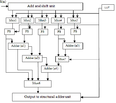
B. Architecture of Programmable Shift Method
The PSM approach is based on the common subexpression elimination algorithm presented. Unlike the CSM method where constant shifts are used, the PSM employs programmable shifters. The advantage of PSM over CSM is that the former architecture always ensures the minimum number of additions and thus minimum power consumption. This is because PSM has a pre analysis part. The filter coefficients are analyzed using the CSE algorithm [7]. Thus the redundant computations (additions) are eliminated and the resulting coefficients in a coded format are stored in the LUT. The coding can be explained as given below. Consider the coefficient h,
h = [1010011001010011] (17)
By using the CSE, substituting 2= [1 1], 3= [1 0 1], (16) becomes
h = [3000020003000020] (18) Then (12) will be stored in the LUT as
43
have 8 possible combinations (from [000] to [111]), it requires 3 bits, and y can have values from [0001] to [1111] for a 16-bit coefficient and hence requires 4 bits. (It must be noted that 2−1 is being applied always after final addition (17) and hence 2−16 will not occur). Thus for storing {x,y} 7 bits are required. The shift and add unit is identical for both PSM and CSM. The number of multiplexer units required can be obtained from the filter coefficients after the application of greedy CSE. The number of multiplexers will be corresponding to the coefficient that has the maximum number of operands. The architecture for the PSM method with programmable shifts (PS) is shown in Fig. 3.
The steps involved in PSM are as follows:
Step 1: Obtain the BCSs from filter coefficients using CSE algorithm.
Step 2: Store the resultant coefficients in the prescribed format as in (18) in the LUT.
Step 3: Get the input x.
Step 4: Get the coefficients from the LUT and use as the select signal for the multiplexers and the programmable shifters.
Step 5: Perform the final shifting function on the output of the multiplexer using PS.
Fig. 3 PSM architecture for 16bit coefficient
Step 6: Perform the addition of intermediate sums using the final adder unit.
Step 7: Store the final result, h*x, in the delay unit „D‟.
Step 8: Go to step 4 if the coefficients in the LUT are not finished, else go to 3
5 RESULTS AND COMPARISON
In this section, the synthesis results of the binary CSE and greedy CSE CSM and PSM architectures are presented and parameters like area, power and delay are compared. The Xilinx 12.3i ISE used for synthesizing purposes. Table shows the synthesis results of CSM and PSM 16-tap FIR filter that has a coefficient wordlength of 16 bits.
Table V Delay Comparison between Binary CSE and Greedy CSE
PARAMETER Binary CSE Greedy CSE
DELAY(ns) CSM PSM CSM PSM
10.045 10.750 9.576 9.651
Table VI Area Comparison between CSM and PSM
PARAMETER Binary CSE Greedy CSE
Number of Gate Count CSM 1525 PSM 1504 CSM 1516 PSM 1495
Table VII Power Comparison between CSM and PSM
The comparison table V shows that greedy CSE CSM architecture
results in high speed filters and the comparison table VI and VII shows the greedy CSE PSM architecture results in low power and low area filter implementations.
6 CONCLUSION
The proposed two new approaches are CSM and PSM, for implementing reconfigurable higher order filters with low complexity. The proposed CSM and PSM methods make use of architectures with fixed number of multiplexers and the reduction in complexity is achieved by applying the greedy CSE algorithm. The CSM architecture results in high speed filters and PSM architecture results in low area and thus low power filter implementations. The PSM also provides the flexibility of changing the filter coefficient
wordlengths dynamically. The proposed reconfigurable
architectures can be easily modified to employ any common subexpression elimination (CSE) method, which results in architectures that offers good area and power reductions and speed improvement reconfigurable FIR filter implementations.
ACKNOWLEDGEMENT
The authors thank the Management and Principal, of Sri Ramakrishna Engineering College, Coimbatore for providing excellent computing facilities and encouragement.
REFERENCES
1. Mahesh, R. and Vinod A. P. (2010) „New Reconfigurable
Architectures for Implementing FIR Filters with Low Complexity‟, computer-aided design of integrated circuits and systems, Vol. 29, No. 2.
2. Vinod, A.P. and Lai, E.(2006) „Low Power and
High-Speed Implementation of FIR Filters for Software Defined Radio Receivers‟, IEEE Trans. WirelessCommun., Vol. 5, No. 7, pp. 1669–1675.
3. Mitola,J.(2000) “Object-oriented approach wireless
systems engineering,” in Software Radio Architecture.
4. Wang,Y.and Mahmoodi,H. (2004) “Hardware architecture
and VLSI implementation of a low-power high-performance polyphase channelizer with applicationsto subband adaptive filtering,” in Proc. IEEE Int. Conf. Acoust. Speech Signal Process, vol. 5., pp. 97–100. 5. Hartley, R.I. (1996) „Subexpression Sharing in Filters
Using Canonic Signed Digit Multipliers‟, IEEE Trans. Circuits Syst. II, Vol. 43, No. 10, pp. 677–688.
PARAMETER Binary CSE Greedy CSE
44
6. Demirsoy, S.S. Kale, I. and Dempster, A.G. (2004)
„Efficient Implementation of Digital Filters Using Novel Reconfigurable Multiplier Blocks‟, in Proc. 38th Asilomar Conf. Signals Syst. Comput., Vol. 1. pp. 461–464.
7. Mahesh, R. and Vinod, A.P. (2006) „Reconfigurable Low
Complexity FIR Filters for Software Radio Receivers‟, in Proc. 17th IEEE Int. Symp. Personal Indoor Mobile Radio Commun. (PIMRC), Helsinki, Finland.
8. Potkonjak, M. Srivastava, B. and Chandrakasan, A.P
(1996) „Multiple Constant Multiplications: Efficient and Versatile Framework and Algorithms for Exploring Common Subexpression Elimination‟, IEEE Trans. Comput.-Aided Design, Vol. 15, No. 2, pp. 151–165.
9. Mahesh, R. and Vinod, A.P. (2008) „A New Common
Subexpression Elimination Algorithm for Realizing Low Complexity Higher Order Digital Filters‟, IEEE Trans. Comput.-Aided Design Integr. Circuits Syst., Vol. 27, No. 2, pp.217–219.
10. Vijay, s. and Vinod, A.P. (2007) „A Greedy Common
![Table IV formed by Table I by substituting HCSs, [1001] =5, [101] =3 and VCS [11] =2](https://thumb-us.123doks.com/thumbv2/123dok_us/9124568.1447486/2.612.317.570.286.443/table-iv-formed-table-i-substituting-hcss-vcs.webp)