http://www.sciencepublishinggroup.com/j/ijbbmb doi: 10.11648/j.ijbbmb.20170203.11
Review Article
Radioactive Ion Beam Targets and the Associated
Processes
Firdous Ahmad Khan
Department of Physics, Government Degree College Anantnag, Anantnag, India
Email address:
To cite this article:
Firdous Ahmad Khan. Radioactive Ion Beam Targets and the Associated Processes. International Journal of Biochemistry, Biophysics & Molecular Biology. Vol. 2, No. 3, 2017, pp. 16-21. doi: 10.11648/j.ijbbmb.20170203.11
Received: July 12, 2017; Accepted: July 20, 2017; Published: September 19, 2017
Abstract:
A large number of targets is required to produce different types of radioactive species. These radioactive ion beams have many uses in addition to their use in various kinds of experiments in different branches of physics. In this article different geometries of RIB targets, the diffusion and surface adsorption processes related to the targets etc. have been explained. Importance of composite thick targets (CTT) and the vacuum infiltration technique used to fabricate such targets have also been discussed.Keywords:
RIB, Diffusion, RVCF, Composite Thick Target, Gamma Spectrum1. Introduction
The field of Radioactive Ion Beams (RIBs) has emerged as one of the most interesting fields in nuclear physics from the last few decades. Many of the nuclear reactions in nuclear physics and astrophysics, inaccessible to experimental study using stable beams can be studied with accelerated RIBs [1, 2]. The study of RIBs have allowed us to explore the properties of isotopes that have a proton-to-neutron ratio very different from the stable isotopes in an unprecedented way [3, 4, 5]. In supernovae nuclear reactions proceed on time scales of typically sec-min. Thus nuclei produced with comparable half lives play a significant role in such nucleosynthesis processes [6]. One can implant and use a selected isotope as a tracer to study the evolution of a protein. There are applications of RIBs in solid state physics [7], materials science, surface sciences, biology, and medicine etc. As the short lived radioactive atoms are not naturally available on earth so they have to be produced through nuclear reactions. There are two complementary techniques to produce good quality RIBs: the Isotope Separation On Line (ISOL) and the Projectile Fragmentation Separator (PFS) technique. In both the techniques targets are irradiated by projectile particle beams and nuclear reactions take place.
There is thus a demand for targets that satisfy different conditions required for a suitable RIB target [8, 9]. Now different
properties of RIB targets on which their selection is made, the design criteria, and how they are prepared will be discussed.
2. Target Material Requirements
3. Target Geometries
Geometry of a target material plays an important and vital
role in the fabrication of efficient target materials. On solving Fick's second law by variables separable method its solution can be carried out for three different kinds of target geometries,
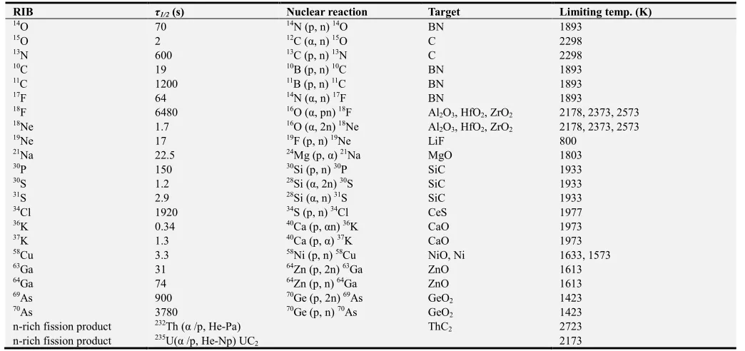
Table 1. Tentative list of RIBs with the corresponding target materials.
RIB τ1/2 (s) Nuclear reaction Target Limiting temp. (K)
14O 70 14N (p, n) 14O BN 1893
15O 2 12C (α, n) 15O C 2298
13N 600 13C (p, n) 13N C 2298
10C 19 10B (p, n) 10C BN 1893
11C 1200 11B (p, n) 11C BN 1893
17F 64 14N (α, n) 17F BN 1893
18F 6480 16O (α, pn) 18F Al
2O3, HfO2, ZrO2 2178, 2373, 2573
18Ne 1.7 16O (α, 2n) 18Ne Al
2O3, HfO2, ZrO2 2178, 2373, 2573
19Ne 17 19F (p, n) 19Ne LiF 800
21Na 22.5 24Mg (p, α) 21Na MgO 1803
30P 150 30Si (p, n) 30P SiC 1933
30S 1.2 28Si (α, 2n) 30S SiC 1933
31S 2.9 28Si (α, n) 31S SiC 1933
34Cl 1920 34S (p, n) 34Cl CeS 1977
36K 0.34 40Ca (p, αn) 36K CaO 1973
37K 1.3 40Ca (p, α) 37K CaO 1973
58Cu 3.3 58Ni (p, n) 58Cu NiO, Ni 1633, 1573
63Ga 31 64Zn (p, 2n) 63Ga ZnO 1613
64Ga 74 64Zn (p, n) 64Ga ZnO 1613
69As 900 70Ge (p, 2n) 69As GeO
2 1423
70As 3780 70Ge (p, n) 70As GeO
2 1423
n-rich fission product 232Th (α /p, He-Pa) ThC
2 2723
n-rich fission product 235U(α /p, He-Np) UC
2 2173
e.g., spherical (powder), cylindrical (fiber) and planar (foil) geometries [10, 11]. For spherical, cylindrical and planar geometries, the analytical expressions for the optimum target thicknesses are given as:
A sphere of diameter, ds
ds (cm) = 2π{Dτ1/2}1/2 (1)
A cylinder of diameter, dc:
dc (cm) = 4.8{Dτ1/2}1/2 (2)
A plate of thickness, x:
x (cm) = π {Dτ1/2}1/2 (3)
Where τ1/2 = half-life of the produced radioactive species. Thus, by taking care of the target dimensions according to the above basic equations the release rate of a particular radioactive isotope can be optimized. These dimensional criteria play an important and vital role in the design of targets. Now there are two important experimental observables F(t') and Y(α)which tell how efficient and useful a target is. F(t'), called the fractional activity, measures the fraction of isotopes still remaining in the target [12]. Its rapid decrease with time is the sign of a useful system.
ˊ ∑ ˊ
(4)
assuming a homogeneous isotope distribution as initial condition. The coefficients cm are given by cm= (m -1/2)2, (j0, m/ π)2 and m2, for the three geometries, foil (n = 1), fiber (n = 2) and particle (n = 3) respectively. j0, m is the mth positive root of the Bessel function of order zero and t' is a unitless scaling
parameter and is related to diffusion time τD and heating time t as
t' = t/τD and τD = a2/(π2D) (5)
where a foil of thickness 2a, a fiber or a particle of diameter 2a are assumed. D is the diffusion coefficient. Using the expression for F(t'), the experimental release data can be used to obtain an effective diffusion constant for a given target material at a given temperature. Such calculations are carried out using a software called Radioactive Ion Beam Optimizer (RIBO) [13].
Figure 1. Fraction of radioisotopes F(t') vs scaled diffusion parameter t' for the three geometries.
< ̂> = , , (6)
respectively, for n = 1, 2 and 3.
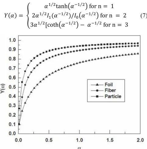
Another quantity Y(α), called diffusion yield, is of great importance and is used in characterizing an on-line system [16]. It measures the quantity of the radioactive species that comes out of the target material before decaying. The probability of such an escape is given by [17]
⁄ tanh% ⁄ & for n 1
2 ⁄ , ⁄ /,.% ⁄ & for n 2
3 ⁄ 0coth% ⁄ & 2 ⁄ for n 3
(7)
Figure 2. Diffusion yield Y(α) vs α.
respectively, for the three geometries. Here, α = τND/a2, τN is
the mean life of the species and Is(x) is the modified Bessel
function of order s. For small α values which indicates the limit of the short-lived radioisotope, Y(α) tends to α1/2, 2α1/2 and 3α1/2 for n =1, 2 and 3 resp. It is also seen that the limiting form is proportional to the dimensionality of the geometry of the target i.e., n. For foil, fiber and particle with the same a the mean escape time of diffusion is in the ratio of 5: 1.875: 1 for a long-lived radioisotope, while the diffusion yield is in the ratio of 1: 2: 3 for a sufficiently short-lived radioisotope. Figure 1 shows how F(t') varies as a function of t' for the three geometries when D ~ 10-7 cm2/s. The Figures 1 and 2 show that F(t') falls more rapidly for spherical (particle) geometry and also Y(α) attains its limiting value much more quickly than the other two geometries. Thus the particle target geometry appears to be the most preferred.
4. Diffusion
Whenever the nuclear reactions take place in a target material, the radioactive species produced have to be taken out from the target to carry out some useful experiments. As there is a concentration gradient of radioactive atoms they will move through the target until an equilibrium state is reached [18]. The net flux, J, of the radioactive species is related to the concentration gradient by Fick's first law as
J = -D334 (8)
Its time-dependent form is Fick's second law which allows for the creation S(x, t) and the lossof particles as given by relation
3
3 5
3
34 6 7 8, 2 9 8, (9)
Where D is assumed to be independent of concentration. One- and three-dimensional forms of Fick's second law can be solved using a simulation program called DIFFUSE [19]. It can also be used to determine the diffusion coefficient D for a particular target material combination. Fick's second law can be solved by variables separable method for three different kinds of target geometries e.g., spherical (particle/powder/grains), cylindrical (fiber) and planar (foil) geometries. In case of a uniform distribution of radioactive species with a primary ion beam intensity I and charge Z, the production rate density S is given by
S(x,t) = =>?:;< (10)
e = electron charge, n = number of interaction nuclei per unit volume, l = length of target material, σ = production cross-section of the species, V = volume of the irradiated sample. While the same for a Gaussian distribution is given as
S(x,t) = :;<
=>?@√ exp 02 E 82 F 8 G H⁄ I J (11)
It is the case with an ion implanted distribution. Where a is the standard deviation of the distribution and <x> is the depth of the distribution from the surface. σnl =1 for the ion implantation experiments. The energy loss function of the projectile in the target material is calculated by the use of computer code SRIM [20], which is then used to numerically determine <x> and distribution of the implanted species within the target material. These parameters depend on the projectile, projectile energy, density and atomic number of the target material. The distribution function of the implanted species is used to derive the parameters for the creation function S. The output of the SRIM is used as input into ANSYS [21] to calculate the temperature distribution in the target material. The E term is given by
E(x,t) = nλ (12) Where λ = 0.693/τ1/2. This term usually vanishes for stable element ion implantation. For solids, the diffusion coefficient, D, is dependent on the energy required to move the atoms or vacancies from site to site (activation energy), HA and the temperature T as
D = D0exp{-HA/kT} (13)
its slope. A very useful empirical relation [22] has been given as HA~ 38TM (14)
where TM is the melting temperature of the material.
In order to maximize the release of radioactive species from the target, it is necessary to operate the target at high temperatures. The target limiting temperature is set by the temperature at which the vapor pressure adversely affects the ionisation efficiency of the ion source. When the target temperature becomes of the order of half of its melting point, there occurs a net grain growth and removal of pores due to the coalescence of neighbouring grains in a local cluster. This process is called “sintering”, results in a longer diffusion time and hence prevents the smooth passage of the radioactive species from within the target [23]. However by using the doping techniques, the effect of sintering in the targets can be lowered.
5. Surface Adsorption
While diffusing out of the target material, the radioactive species produced may stick to the surface of the vapor transport tube due to the process of adsorption. This time delay, that is excessively long in relation to the life-time of the radioactive species, results in a significant loss of beam intensity. The extent of loss due to adsorption is given by the residence time of a particle on a surface. It depends upon the temperature as is given by Frenkel equation:
τ= τ0exp[Had/kT] (15)
where Had is the heat of adsorption, k is Boltzmann constant, T the absolute temperature, τ0 is the time required for a single
lattice vibration (~ 10-13s). The heat of adsorption value depends upon the adsorbent/adsorbate combination.
In thermal equilibrium with a surface the desorption rate of adsorbed atoms per unit area is given by
KL
K 7 M N
OPexp02Q@K⁄ JRM (16)
where the temperature dependent function S(T) gives the probability that the particle will stick to the surface, N the number of atoms adsorbed per unit area, and ω0/2π = 1/τ0.
Now as it is desirable to minimize the residence times of the radioactive ions on the surface of the target ion source, so the choice of the materials of construction for the vapor transport system is extremely important. It has been found that coating the inner surfaces of the transport tube with materials of low enthalpy of adsorption significantly reduce residence times. Thus the nobel metals such as iridium, rhenium etc. are suitable for this use [24].
6. Composite Thick Targets
The intensity of a radioactive ion beam is given by
I = σ.NT.ϕ.εtarget.εsource.εsep.εtransp (17)
σ = reaction cross-section (cm2), NT = number of target atoms per unit area (cm-2), ϕ = primary beam intensity, εtarget
the target efficiency, εsource the ion source efficiency, εsep the
mass separator efficiency and εtransp efficiency of transmission
to the user set-up. For a particular nuclear reaction σ is fixed and if ϕ is also constant then I depends only on the number of target nuclei per unit area. In the energy range 30 - 100 MeV, the typical target thickness is ~ few gm/cm2, while at about 500 MeV proton energy the typical target thickness is ~ few hundred gm/cm2. As in case of thick targets practically no atoms come out from deep inside the thick target. As I depends on NT so it is advisable to achieve the given thickness with the maximum possible surface area. One way to do this is to use a large number of thin targets stacked together instead of one thick target. But experiments show that these thin foils don’t allow the radioactive species to diffuse easily. So it is rather desirable to find a low density, highly permeable matrix for the target deposition [25].
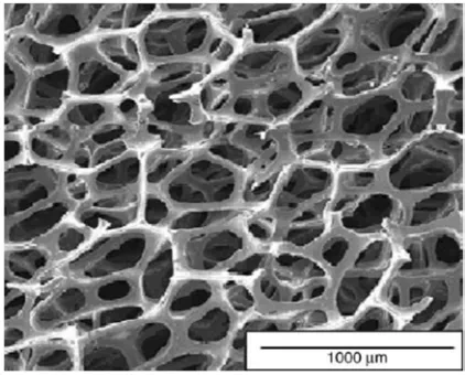
The low-density target matrices such as Reticulated Vitreous Carbon Fibers (RVCF) are the suitable carbon thick targets as well as used for the deposition of other target materials. It is specially made carbon foam, where the cylindrical fibers (5-6µm diameter) are continuous ligament structures. RVCF has the advantage of higher surface-to-volume ratio (RS/V), the efficient transport of heat deposited in the target by the primary beam and good machining characteristics. Since matrices with higher compression ratios have larger surface-to-volume ratios for a given target material coating thickness, targets can be shortened by using compressed RVCF. RVCF occurs in uncompressed (ρ ~ 3.3% ρ0 ~ 0.05 g/cm3) and compressed forms, where ρ and ρ0 are the respective densities of RVCF with ρ0 ≈ 1.538 g/cm3, which is the density of the solid glass carbon. For uncompressed RVCF, the surface-to-volume ratio is ≈ 32.2 cm2/cm3. 2xRVCF, 4xRVCF and 6xRVCF are respectively compressed by a factor of 2, 4 and 6 in one direction and their surface-to-volume ratios are 64.4, 128.8, 193.2 cm2/cm3 respectively. Many target materials (e.g., UC2,
SiC etc.) have been successfully deposited on RVCF to fabricate high-quality, robust and tightly bound highly permeable targets.
7. Vacuum Infiltration Technique
The technique which is used for target deposition must be able to infiltrate the target matrix while controlling the uniformity and thickness of the target. There are many techniques to fabricate RIB targets e.g., physical vapor deposition (PVD), electrophoresis deposition (ED), sol-gel coating (SGC), Chemical Vapor Infiltration (CVI) technique, Chemical Vapor Deposition (CVD) technique and electrolytic deposition technique. As the target designs require deposition of controlled thickness of the target materials onto the interior surfaces of highly permeable matrices, most of these techniques are inappropriate. Besides, each of these techniques is target specific.
Some of the techniques like CVI and CVD are very time consuming and expensive. PVD is limited to line-of-sight deposition. SGC and CVI/CVD involve a number of complex chemical reactions. A new technique, called vacuum
infiltration technique, of depositing a variety of target materials on RVCF has been developed. It being very fast, close to universal infiltration coating technique and inexpensive is used widely. A drawing of the apparatus is shown in Figure 4.
This technique is used for uniform deposition of target compounds onto highly permeable matrices to form short diffusion length targets. Here the target material is reduced to fine powder with powder particle size ~ 1µm with an ultrasonic milling device, typically operated for 40 minutes and then mixed into commercially available binder. Besides, a commercially available dispersant is added to the mixture in order to prevent the individual particles from aggregating. The methodology is based on the vacuum coating of this mixture onto RVCF. If the target material and the RVCF interact, then the RVCF is pre-coated with a thin layer (~ 1-2µm) of chemically inert material (e.g., Ta, W etc.) to prevent reduction reactions.
Figure 4. A drawing of the vacuum infiltration apparatus.
The apparatus consists of a container equipped with a tapered (45°) holder machined into the top face for capturing RVCF discs. A hole with diameter ~1mm is drilled from the apex of the taper through the container. It is used for pulling air through the sample during infiltration coating on connecting the container to a mechanical vacuum pump through a valve. The excess target material is efficiently trapped in a small container that screws directly beneath the sample holder port. This feature is especially important for radioactive material target fabrication.
During coating the valve is opened to pull air through the target matrix. To ensure uniformity of target material/binder-solution, it is vigorously shaken by using an ultra-sonic vibrator during the deposition process. The target material solution is aspirated over the RVCF disc. When the vacuum forces pull the fluid through the sample it is turned over using tweezers. The vacuum is used to pull the target material back through the RVCF disc in order to ensure uniformity in coating.
After coating, the target samples are out-gassed in a vacuum
furnace with pressure reduced to ~ 100 mbar. Then to drive off the volatile components of the binder solution the target temperature is gradually and linearly increased to a temperature ~ 350°C.
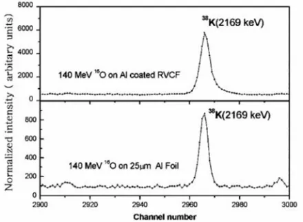
Figure 5. γ-spectrum containing 2169 keV γ-peak of38K produced from “thick”
The Figure 5 shows a portion of the gamma spectrum which compares the yields of the released radioactive species from a composite thick target and a plain thin foil target [26]. To fabricate a composite thick target aluminium was deposited on a RVCF disc by physical vapor deposition. The disc had a surface area of 32.2 cm2/cm3. O16 beam, from VECC cyclotron, Kolkata, India produced Al27(O16, αn)K38 reaction. High-Purity Germanium detector (HPGe) measured the yields from the gamma emission. The measurements showed an enhancement of 7.1 times in yield for the composite target compared to the plain thin foil target. This enhancement was due to the higher surface to volume ratio of the composite thick target and is quite close to the theoretically predicted value of 8.6 times.
8. Conclusion
There is need of a large number of robust and efficient radioactive ion beam targets for use in nuclear physics and other branches of physics. Radioactive ion beams are used to explore the properties of isotopes that have a proton-to-neutron ratio very different from the stable, to study supernovae nuclear reactions and other nucleosynthesis processes. One can study the evolution of a protein using such beams. There are applications of RIBs in solid state physics, materials science, surface sciences, biology, and medicine as well.
Fick's second equation can be solved for three types of geometries, namely spherical, cylindrical and planar geometries. But the spherical geometry comes out to be the most efficient of the three. Though the diffusion rate of the radioactive species can be increased with temperature, but it gives rise to sintering at higher and higher temperatures which reduces the diffusion rate significantly. Adding some dopants to the target material reduce the sintering. The chemical nature of the target should be so that the radioactive species produced spends less time inside which minimizes the residence time.
As the intensity of a radioactive ion beam also depends on the number of target nuclei per unit area and because no atoms come out from deep inside the thick target, so it is desirable to achieve the given thickness with the maximum possible surface area. RVCF is a suitable material to act as matrix for the deposition of target materials. It has a large surface-to-volume ratio and efficiently transports the heat deposited in the target by the primary beam. This increase in the surface-to-volume ratio increases the yield by an order of magnitude. The vacuum infiltration technique, used to fabricate composite thick targets, is a fast, inexpensive, close to universal infiltration coating technique and uniformity promising.
References
[1] G. D. Alton, J. R. Beene, J. Phys. G 24 (1998) 1347.
[2] G. D. Alton, J. R. Beene, R. L. Auble, D. Stracener, Indian J. Phys. 76S (2002) 9.
[3] I. Tanihata. et al., Phys. Lett. B 160 (1985) 380. [4] P. G. Hansen, B. Jonson, Europhys. Lett. 4 (1987) 409. [5] W. Schwab, et al., Z. Phys. A 350 (1995) 283. [6] A. E. Champagne, Isospin Lab. works. ORNL (1992). [7] H. Haas, Isospin Lab. workshop, ORNL (1992).
[8] Y. Zhang, G. D. Alton, Nucl. Instr. and Meth. A 521 (2004) 72. [9] G. D. Alton, J. C. Bilheux, A. D. McMillan, Nucl. Instr. and
Meth. A 521 (2004) 108.
[10] J. Crank, The Mathematics of Diffusion, second ed., Claredon, Oxford, 1975.
[11] H. S. Carslow, J. C. Jaeger, Conduction of heat in solids, second ed., Clarendon, Oxford, 1959.
[12] H. L. Ravn, et al., Nucl. Instr. and Meth. 139 (1976) 267. [13] www.cern.ch/ribo.
[14] H. L. Ravn, L. C Carraz, J. Denimal, E. Kugler, M. Skarestad, S. Sundell and L. Westgaard, Nucl. Instr. and Meth. 139(1976) 267.
[15] L. C. Carraz, I. R. Haldorsen, H. L. Ravn, M. Skarestad and L. Westgaard, Nucl. Instr. and Meth. 148 (1978) 217.
[16] M. Fujioka, Y. Arai, Nucl. Instr. and Meth. 186 (1981) 409. [17] H. L. Ravn, S. Sundell and L. Westgaard, J. Inorg. Nucl. Chem
37 (1975) 383.
[18] Diffusion in the condensed state, eds. J. S. Kirkaldy and D. J. Young (The Institute of Metals, London, 1987), Ch. 1. [19] DIFFUSE is a code that solves Fick’s second equation. It was
written by G. D. Alton, J. Dellwo and I. Y. Lee.
[20] J. F. Ziegler, The transport of ions in Matter, SRIM2003, IBM Research, Yorktown Heights, New York 10598, USA, 2003. [21] ANSYS is a finite element computer program an product of