Reflectionless High-Selective Bandpass Filter Based on Acoustic
Wave Resonators
Jordi Verd´u*, Daniel Ulinic, and Pedro de Paco
Abstract—Reflective filters are characterized by a frequency response with good matching at the band of interest and usually reactive impedance out of those frequencies which may adversely affect the system performance. On the other hand, reflectionless filters are characterized by good matching characteristic not only at the interest frequencies, but in the whole frequency spectrum which improves the overall linearity, efficiency, and reduces instability scenarios at the system level. Although several reflectionless structures can be found in the literature, the concatenation of different reflectionless sections, combined with the use of acoustic resonators has not been exploited yet. The particular electrical behavior of acoustic wave resonators, where two different resonant frequencies are found, allow to obtain a frequency response with high selectivity due to the presence of transmission zeros below and above the passband. A bandpass filter has been designed following the described procedure with a fractional bandwidth F BW = 2%, a pair of transmission zeros below and above the bandpass, and an improved out-of-band rejection with respect conventional topologies.
1. INTRODUCTION
Reflective filters are the most popular solution in charge of shaping the spectrum content, but simultaneously are responsible for several practical difficulties including: potential instability of integrated amplifiers with high out-of-band gain and unpredictable nonlinear effects resulting from the reactive harmonic loading, as well as potential damage to high-power transmitters with large harmonic content [1]. On the other hand, reflectionless became an attractive solution to previous difficulties since good matching condition is achieved not only at the interest frequency band, but also in the outer regions. This can be achieved by taking advantage of complementary even- and odd-mode equivalent circuits as seen in [2–4]. Also dissipative impedance matching sections can be used in order to cancel the reflected wave by means of lumped elements [5], but also using other technologies, for example multilayer stripline [6].
Moreover, from the filter point of view, the reflectionless condition is also useful in order to obtain more sophisticated frequency responses since different filtering sections can be directly concatenated without the need to include any extra matching mechanism. This has been proposed in [4], where the cascading is used to have a control on the achievable bandwidth of the filter response, but also with the aim of designing duplexers.
Although several reflectionless structures have been previously reported, the use of acoustic technology has not been exploited in this class of filters. In this sense, acoustic wave resonators (SAW/BAW) show a particular frequency behavior characterized by two resonant frequencies [7, 8] at which the input impedance is zero and infinite. Taking advantage of extracted pole nature of such resonators, very high-selective bandpass responses can be achieved due to the presence of transmission
Received 24 July 2018, Accepted 25 September 2018, Scheduled 12 November 2018
* Corresponding author: Jordi Verd´u ([email protected]).
transmission zeros can be controlled as it will be shown in the design procedure.
This work presents a very high-selective reflectionless bandpass filter with improved out-of-band rejection based on AW resonators. First, the lowpass protoype will be discussed. Then, taking advantage of the properties of reflectionless structures and the properties of acoustic wave resonators, the design procedure for a bandpass response with transmission zeros below and above the passband is described. As a validation example, a bandpass filter is shown using fabricated AW resonators, with a fractional bandwidthF BW = 2% and a pair of transmission zeros below and above the passband. In addition, the effects on the return losses of possible unbalances in the structure are described. Finally, the conclusions are presented.
2. LOWPASS PROTOTYPES BASED ON AW RESONATORS
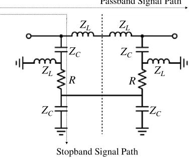
The design of the lowpass reflectionless microwave filters is based on the connection of two highpass prototypes networks taking advantage of the even- and odd-mode equivalent circuits [2, 3]. Although this work is focused on the design of a bandpass filter, other arrangements in the lowpass prototype are suitable to obtain bandstop frequency responses [4]. A perfect matching condition (S11= 0) entails that Γeven =−Γodd, which is equivalent tozeven=yodd. The constraints to keep duality and symmetry lead to the prototype in Fig. 1, as explained in [2], where the dashed line represents the symmetry plane. Although extra elements can be added to have more flexibility [2], the value of the elements must follow the next relation,
ZL= 1/ZC (1)
The electrical behavior of the AW resonator is usually modeled in the bandpass domain by the Butterworth-Van Dyke (BVD) model, formed by a series LAW-CAW tank, modeling the acoustic behavior, in parallel with a static capacitance C0 modeling the electric behavior [9]. On the other hand, the dangling resonator is an attractive and useful representation of the lowpass model [7, 10] which is at the same time related with the lowpass BVD model as shown in Fig. 2. The impedance of the series AW resonator is defined for the lowpass BVD equivalent circuit as,
ZAW(Ω) = jXSE−0
(ΩLSE−m+XSE−m) XSE−0+ ΩLSE−m+XSE−m
(2)
As previously commented, the frequency solution leading to ZAW = 0 Ω is known as the resonance frequency fr (also series frequency), while the frequency solution for ZAW = ∞ Ω is known as anti-resonance frequencyfa(also parallel frequency). The frequency difference betweenfrandfais given by the electromechanical coupling constantk2eff which is a parameter defined by the material system [10]. As will be further discussed, this is directly related with the bandwidth of the filter response.
ZL ZL
ZL
ZL
R R
ZC ZC
ZC
ZC
Passband Signal Path
Stopband Signal Path
B JR
b
JML -JML
JR
-JML
JML
jB
jb s
LSE-m jXSE-m
jXSE-0
(b)
(a) (c)
Figure 2. Nodal representation (a), Equivalent circuit schematic (b) and lowpass BVD model (c) for the series AW resonator.
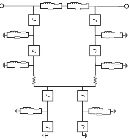
Figure 3. Basic configuration for the lowpass reflectionless prototype based on AW resonators (Section 1).
Taking into consideration the symmetry conditions mentioned above but also the technological restrictions which forces the specific BVD model, the configuration in Fig. 1 can be modified to the case of using AW resonators as shown in Fig. 3 (Section 1). The inversion of the impedance, as stated in Eq. (1), is achieved by means of unitary admittance inverters, being J = 1 in the lowpass prototype. The source and load terminations are normalized to R = 1 Ω. It is important to state that the AW resonator is the same for the whole structure. This is positive from the technological point of view, but also in order to minimize unwanted unbalances as will be further discussed.
The obtained transmission response for configuration in Fig. 3 is shown in Fig. 4 together with the electrical behavior of the AW resonator. At fr1 the AW resonator behaves as a short-circuit in the passband signal path, and open-circuit in the stopband signal path, while at fa1, the passband signal path is blocked, which entails a transmission zero at such a frequency. The transmission zero observed close to the bandpass occurs at the central frequency of the AW resonator, that is,f0i=
√
frifai, where
Figure 4. Transmission responseS21for Section 1 and electrical input impedance of the AW resonator.
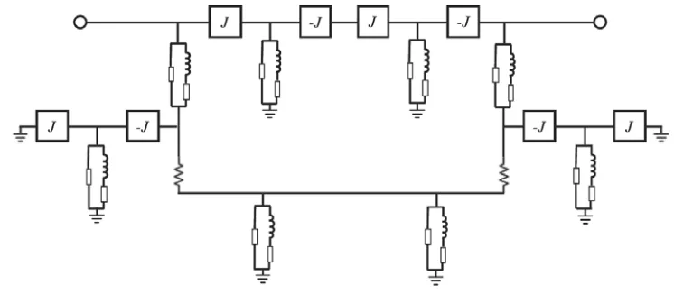
Figure 5. Complementary configuration (Section 2).
Based on this basic configuration in Fig. 3, the complementary structure can also be considered as shown in Fig. 5 (Section 2). Unlike the previous case, the signal is blocked in the passband signal path atfr2 since the impedance of the AW resonator is 0 Ω which is between admittance inverters. The frequency at the bandpass is now found at fa2 resulting in the transmission response shown in Fig. 6. Again, the return losses have been avoided in the figure since they are negligible.
3. DESIGN PROCEDURE FOR CONCATENATED SECTIONS
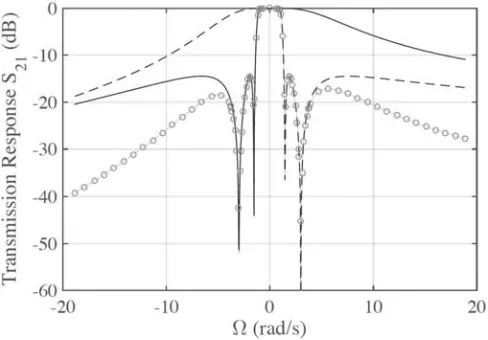
In order to obtain high selectivity below and above the passband, and also an improved out-of-band rejection, the complementary configurations in Fig. 3 and Fig. 5 can be concatenated without loading effects of one on the other since perfect matching is achieved at the whole frequency range. The transmission response of the concatenated sections configuration is shown in Fig. 7 (gray symbol line), together with the transmission response for each of the used sections. As it was predictable, the loading effects of one section on the other are negligible.
In a conventional Ladder-type filter, the achievable filter bandwidth is directly related with the electromechanical coupling constant k2
eff [12]. In this case, the transmission zeros are a direct
Figure 6. Transmission responseS21for Section 2 and electrical input impedance of the AW resonator.
Figure 7. Transmission response S21 for the concatenated sections. Dashed line corresponds to the configuration in Fig. 3, solid line corresponds with the complementary configuration Fig. 5, and gray symbol line with the concatenated structure.
structure, there is also one transmission zero closest to the bandpass (above and below), which, as previously described, corresponds to the center frequency of the acoustic resonators. Therefore, the achievable bandwidth for these reflectionless type filters will be approximately half of the conventional ladder-type filters.
Taking these considerations into account and for the sake of simplicity of the design procedure, the acoustic wave resonators can be designed in such a way that fr1 =fa2, where subscripts 1 and 2 refer to Sections 1 and 2, respectively. The bandwidth can be still increased iffr1 is slightly higher thanfa2. Because this difference is higher, the higher ripple in the bandpass will be present as it also occurs in the conventional ladder-type filters.
Finally, the position of the outer transmission zeros will be directly related withfa1 andfr2.
4. HIGH-SELECTIVE BANDPASS FILTER DESIGN
Figure 8. Detail of the transmission response S21 of the bandpass filter and input impedance of the fabricated AW resonator.
Figure 9. Transmission response of the designed filter in a wide frequency range.
Figure 10. In-band group delay of the designed filter.
frequencies and static capacitances: fr1 = 1962 MHz, fa1 = 2019 MHz and C01 = 1.68 pF for the one in Section 1, andfr2 = 1908 MHz,fa2 = 1962 MHz andC02= 1.65 pF for the one in the Section 2. The detail of the obtained transmission response and the input electrical impedance of each resonator are shown in Fig. 8. As expected, the position of the transmission zeros and the center of the passband are consistent with the previously described design procedure. Transmission zeros closer to the bandpass (f = 1935 MHz and f = 1991 MHz) and in the out-of-band region (f = 1600 MHz and f = 2275 MHz) are solutions for S21 = 0, when zeven = yodd. The rest of transmission zeros
(f = 1908 MHz andf = 2019 MHz) occur whenzeven = 0 Ω andyodd = 0 S, atfr2 and fa1, respectively. Figure 9 shows the transmission response of the designed filter in a wide frequency range. A spurious resonance can be observed close to 3.2 GHz. This resonance is due to the intrinsic behavior of the used BAW resonators which could be avoided for example including a thickened edge load in the top electrode as discussed [13]. Unlike conventional Ladder-type filters, the out-of-band rejection is decreasing monotonically.
Table 1. Different designed reflectionless filters comparison.
This work [2] [3] [4] [5] [6]
Filter Techonology AW Lumped MMIC Lumped/Planar Lumped Multi-layered
f0 1962 MHz 185 MHz 2600 MHz 250/1000 MHz 100 MHz C-Band
F BW 2% 94% 30%
10%/12,5%
(Reconfigurable)
50% 67%
Control of Tx Zeros Yes Yes Yes Yes No Yes
this is not constantly flat, the results are comparable with solutions as the one in [14].
Table 1 shows the comparison with previous designed reflectionless filters. As previously mentioned, this is the first filter based on Acoustic Wave resonators to the best knowledge of the authors; therefore, the comparison with previous works only intend to offer an overview of what it can be achieved. Unlike filters based on lumped components, the quality factor of the resonators is Q= 1500, which allows to obtain deep transmission zeros, however, the group delay is increased at the edges of the bandpass as shown in Fig. 10. Also, as seen in the comparison, this topology is used for narrow-band applications, in this case with a relative bandwidth of F BW = 2%, unlike other configurations that may present values aboveF BW = 10%.
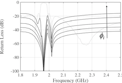
With the aim of studying the effect of the unbalance on the return losses, the co-simulation has been carried out including a phase shifter in one of the branches of the used sections. It has to be pointed out that the effect of unbalancing both sections at the same time does not substantially affect the overall return losses since the observed level is very low. The values of the phase shifter areφi = 0.5, 1, 2, 5 and 10◦, where φi = 0.5◦ corresponds to the case of lower return losses in Fig. 11. Since the return losses are so low, the transmission response of the filter is not affected in any case.
Figure 11. Effect of the phase unbalance on the return losses forφi= 0.5◦, 1◦, 2◦, 5◦ and 10◦.
5. CONCLUSIONS
effect of unbalance has also been considered, obtaining return losses better than 20 dB for an unbalance of φi= 5◦, without affecting the insertion losses. A bandpass filter using fabricated BAW-SMR resonators
has been presented to validate the proposed topology.
ACKNOWLEDGMENT
This work was supported in part by the Spanish Ministerio de Econom´ıa y Competitividad under grant TEC2015-69229-R.
REFERENCES
1. Chappell, W. J., E. J. Naglich, C. Maxey, and A. C. Guyette, “Putting the radio in software-defined radio: Hardware developments for adaptable RF systems,”Proceedings of the IEEE, Vol. 102, 307– 320, 2014.
2. Morgan, M. A. and T. A. Boyd, “Theoretical and experimental study of a new class of reflectionless filter,” IEEE Transactions on Microwave Theory and Techniques, Vol. 59, 1214–1221, 2011. 3. Morgan, M. A. and T. A. Boyd, “Reflectionless filter structures,”IEEE Transactions on Microwave
Theory and Techniques, Vol. 63, 1263–1271, 2015.
4. Psychogiou, D. and R. Gomez-Garcia, “Reflectionless adaptive RF filters: Bandpass, bandstop and cascade designs,” IEEE Transactions on Microwave Theory and Techniques, Vol. 65, 4593–4605, 2017.
5. Lee, T.-H., B. Lee, and J. Lee, “First-order reflectionless lumped-element lowpass filter (LPF) and bandpass filter (BPF) design,”IEEE MTT-S International Microwave Symposium (IMS), 1–4, 2016.
6. Morimoto, Y., T. Yuasa, T. Owada, Y. Tahara, H. Miyashita, M. Miyazaki, M. Memarian, and T. Itoh, “A multiharmonic absorption circuit using quasi-multilayered striplines for RF power amplifiers,”IEEE Transactions on Microwave Theory and Techniques, Vol. 65, 109–118, 2017. 7. Verdu, J., I. Evdokimova, P. de Paco, T. Bauer, and K. Wagner, “Synthesis methodology for the
design of acoustic wave stand-alone ladder filters, duplexers and multiplexers,”IEEE International Ultrasonics Symposium, 2017.
8. Triano, A., J. Verdu, P. de Paco, T. Bauer, and K. Wagner, ‘Relation between electromagnetic coupling effects and network synthesis for aw ladder type filters,”IEEE International Ultrasonics Symposium, 2017.
9. Larson III, J., P. Bradley, S. Wartenberg, and R. Ruby, “Modified butterworth-Van dyke circuit for FBAR resonators and automated measurement system,” IEEE International Ultrasonics Symposium, 2000.
10. Gimenez, A., J. Verdu, and P. De Paco,“General synthesis methodology for the design of acoustic wave ladder filters and duplexers,”IEEE Access, Vol. 6, 1–11, 2011.
11. Gomez-Garcia, R., M. Sanchez-Renedo, B. Jarry, J. Lintignat, and B. Barelaud, “A class of microwave transversal signal-interference dual-passband planar filters,” IEEE Microwave and Wireless Components Letters, Vol. 19, 158–160, 2009.
12. Menendez, O., P. de Paco, E. Corrales, and J. Verdu, “Procedure for the design of Ladder BAW Filters taking electrodes into account,”Progress In Electromagnetics Research Letters, Vol. 7, 127– 137, 2009.
13. Verdu, J., P. de Paco, and O. Menendez, “Electric equivalent circuit for the thickened edge load solution in a Bulk Acoustic Wave Resonator,” Progress in Electromagnetics Research M, Vol. 11, 13–23, 2010.