Dynamics of Self-Generated Magnetic Fields in Stagnation Phase
and their E
ff
ects on Hot Spark Formation
Akiro HATA, Kunioki MIMA, Astushi SUNAHARA
1),
Hideo NAGATOMO and Akio NISHIGUCHI
2)Institute of Laser Engineering, Osaka University, Suita 565-0871, Japan
1)Institute of Laser Technology, Suita 565-0871, Japan 2)Osaka Institute of Technology, Osaka 535-8585, Japan
(Received 29 September 2005/Accepted 3 February 2006)
The generalized temporal evolution equation of a magnetic field is derived for high density laser-fusion plasmas. Magnetic field generation and convection are simulated by using the 2D hydrodynamic code together with the magnetic field equation. It is found that magnetic fields are generated and compressed in association with the Rayleigh-Taylor instability of an imploding shell. In particular, the magnetic field convection by the Nernst effect is found to play an important role in the amplification of magnetic fields. The maximum magnetic field reaches 30 MG at maximum compression. This magnetic field may reduce the electron heat conduction around the hot spark. Therefore, it is concluded that the ignition condition for non-uniform implosion is influenced by self-generated magnetic fields.
c
2006 The Japan Society of Plasma Science and Nuclear Fusion Research
Keywords: laser fusion, magnetic field, Rayleigh-Taylor instability, Nernst effect, convection, heat transport DOI: 10.1585/pfr.1.020
1. Introduction
It is widely known that megagauss magnetic fields are generated in laser plasmas. In the 1970s, Stamper et al. measured a kilogauss magnetic field in a laser-produced plasma [1]. After that, various measurements and simulations have revealed that magnetic fields in high intensity laser-produced plasmas reach the order of 1–100 megagauss [2, 3]. A mechanism that plays a role in self-generated magnetic fields can be explained by the non-parallel density and temperature gradients [4].
In fast ignition, megagauss-order magnetic fields ex-ert significant effects on the electron heat flux [5]. In laser plasmas, a magnetic field is not only generated by non-uniform laser irradiation but also by various instabil-ities such as collisionless and collisional Weibel instabili-ties [6, 7], thermal instability [8], and Rayleigh-Taylor in-stability [9]. When a laser irradiates a solid target, nonpar-allel temperature and density gradients appear due to the Rayleigh-Taylor (RT) instability [10]. The RT instability in the acceleration and the deceleration phases can be the major source of the magnetic field in imploded plasmas. The magnetic fields in the acceleration phase of the im-plosion are convected into the ablation front by the Nernst effect [11]. These magnetic fields then penetrate further inward. The magnetic fields are amplified in the decelera-tion phase as well, where all the magnetic fields are com-pressed rapidly. Therefore, the magnetic fields become strong enough to influence the implosion process.
author’s e-mail: [email protected]
In this paper, we discuss magnetic field generation and its effects on heat transport due to RT instability in the de-celeration phase. In Sec. 2, the basic equations for the mag-netic field’s temporal evolution are derived. Magmag-netic field generation and amplification are simulated in Sec. 3. Sec-tion 4 is devoted to an analysis of the simulaSec-tion results. Finally, Sec. 5 provides a summary and a conclusion.
2. Simulation Model
The temporal evolution of magnetic fields is described by the following Maxwell equation (1) and the equation of electron motion shown in Eq. (2).
∂B
∂t =−c∇ ×E, (1)
whereB,c, andEare the magnetic field, the speed of light, and the electric field, respectively. The equation of electron motion is given by
mene
dVe
dt =−ene
E+1
cVe×B
−∇pe+Rei0, (2)
wherene,me,Ve, andpeare the number density, mass,
ve-locity, and isotropic pressure of electrons, respectively.Rei
is the force due to ion collisions. Here, we assume that the electron inertia is negligible in Eq. (2) and the charge neutralityne=Zni. We define electric current densityJas
u=Ve−Vi=−J/nee=−(c/4πnee)∇ ×B. (3)
c
2006 The Japan Society of Plasma
The electric field EandVeare eliminated from Eqs. (1),
(2), and (3) to obtain ∂B
∂t =∇ ×
Vi×B+
c e
∇ ×∇pe
ne
−∇ ×∇ ×B
×B
4πne − ∇ ×
R
T+Ru
ne
, (4)
where the collision termReiis separated into the thermal
forceRT and the friction force Ru. RT and Ru in Eq. (4)
are defined as follows:
RT=−βuT ∇Te−β⊥uT∇⊥Te−βuT∧ h× ∇Te, (5)
Ru=−αu−α⊥u⊥+α∧h×u, (6)
whereh is a unit vector in the direction of the magnetic field. The vectorsu andu⊥ representh(u·h) and h×
(u×h), respectively.Teis electron temperature, and∇Te
representsh(h· ∇Te). Also∇⊥Terepresentsh×(∇Te×h).
αandβare given by
βuT
=neβ0, βuT⊥ =ne(β
1χ2+β
0)/∆,
βuT
∧ =neχ(β
1χ2+β
0)/∆,
α=meτneα0
e
, α⊥= mτene
e
1−α
1χ2+α
0
∆
,
α∧=mτene
e
χα
1χ 2+α
0
∆ ,
χ=ωeτe, ∆=χ4+δ1χ2+δ0. (7)
Hereχis the Hall parameter,ωe =eB/mcis the electron
cyclotron frequency,τeis electron-ion collision mean free
time, andβ0, β
1, β
0, β
1, β
0, α0, α
1, α
0, α
1, α
0, δ0, andδ1are
thermal transport coefficients, respectively. These coeffi -cients are listed in detail in Ref. [12]. The first term on the right-hand side of Eq. (4) represents the convection and the stretching of the magnetic field by hydrodynamic motion. The second term, (c/e)∇ ×(∇pe/ne), is the source of the
magnetic field, called Rihi Ludac effects. If we treat elec-tron pressure as ideal gas, we obtain the well-known result (c/(ene))∇Te×∇ne. This means that eddy currents are
gen-erated when nonparallel gradients of electron density and temperature exist. The third term on the right-hand side of Eq. (4) shows the ion Hall effect. The Hall effect is impor-tant when the magnetic spatial scale is comparable to ion skin depth. The last term on the right-hand side of Eq. (4) contains the diffusion of the magnetic field and the Nernst effect, which plays an important role in the motion of the magnetic field. The Nernst effect is due to the generation of current perpendicular to the temperature gradient and the magnetic field.
We next concentrate our analysis on the thermal force
RTand the friction forceRu. Inserting Eqs. (5) and (6) into
Eq. (4) together with taking into account the relation of the velocityuin Eq. (3) to the magnetic field, the last term on
the right-hand side of the Eq. (4) is written as
∇ ×
RT+Ru
ne
=−∇ ×β∇Te
−e
c∇×
B×βτe
me∇
Te
+∇×
mec
4πe α0
neτe
h(∇×B)·h
+∇ ×
mec
4πe 1−α
neτe
h×(∇ ×B)×h
+∇ × α 4πne ∇ ×
B×B
. (8)
Here, coefficientsβ,β,α, andαdepending onωeτeare
given by
β=(β1χ2+β
0)/∆, β
=(β1χ2+β
0)/∆,
α =(α
1χ2+α
0)/∆, α
=(α
1χ2+α
0)/∆. (9)
First of all, combining the first term on the right-hand side of Eq. (8) with the∇Te× ∇neterm, the source of the
magnetic field is rewritten as c
e 1 ne∇
Te× ∇ne+
c e∇ ×
β ∇Te=
c
e∇Te× ∇
logne−β
. (10) The second term ∇ × (β∇Te) on the left-hand side of
Eq. (10) denotes the thermal force associated with the electron-ion friction force in the presence of the thermal gradient. Note that∇ ×(β∇Te) is 0 whenB= 0. In
ad-dition, the contribution of∇ ×(β∇Te) to magnetic field
generation is usually smaller than the∇Te× ∇neterm in a
high density plasma.
Nishiguchiet al.[11] have studied the convection pro-cesses of a magnetic field in a laser-produced plasmas in terms of the Nernst effect. This term is written as follows:
∇ ·
Bβτe
me∇
Te
=−∇ ·BVT, VT=−β
τe
me∇
Te.
(11) According to their work, the magnetic field is convected to-ward the lower temperature region with velocityVTwhich
is comparable to the fluid velocityViin a laser-driven
ab-lation. The velocityVTis the heat flow velocity and∇ ·VT
is negative on the ablation front. As a result, the magnetic field is amplified at the ablation front. The third term and the fourth term represent diffusion parallel to the magnetic field and that perpendicular to the magnetic field, respec-tively. Both terms are derived from the friction forceRu.
The last term also originates from the friction force. Ultimately the temporal evolution of the magnetic field is subjected to
∂B
∂t =∇ ×
Vi+VT×B
+c
e
∇Te× ∇logne−β
−∇ ×1+α
4πne
∇×
B×B − ∇ ×
mec
4πe α0
neτe
h(∇×B)·h
−∇ ×
mec
4πe 1−α
neτe
h×(∇ ×B)×h
In summary, it is found that the temporal evolution of the magnetic field is composed of the source, the Nernst effect, diffusion, and the pressure of magnetic field. It is important to notice here that the thermo-electric current
∇Te× ∇neis the only source of the magnetic field.
3. Simulation of Magnetic Field
Gen-eration in the Stagnation Phase
In order to simulate the temporal evolution of the mag-netic field, we use space-time dependent plasma profiles which are obtained by hydrodynamic simulation. The im-ploded fuel pellet is a CH capsule which contains DT fuel. The thickness of the CH capsule shell, solid DT, and gas DT are 2µm, 100µm, and 795µm, respectively.
Figure 1 shows the pulse shape of a 0.35µm wave-length implosion laser. The laser pulse energy is 50 kJ with a corresponding intensity of 1.4×10¹⁴W/cm2. The laser
pulse duration is 3.72 ns.
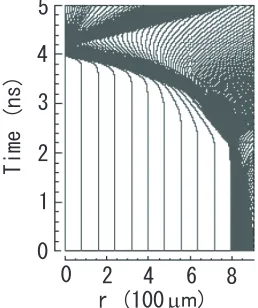
We used the ILESTA-1D code [13] until stagnation phaset=3.9 ns, then 2D simulation was carried out for the plasma profile obtained by 1D calculation. The streamline of the implosion is shown in Fig. 2. At the beginning of
Fig. 1 The pulse shape of 3ωlaser with energy of 50 kJ.
Fig. 2 The R-T diagram of the implosion obtained by the ILESTA-1D code. This 1D code was used until 3.9 ns as an initial condition for the calculation of a magnetic field.
the stagnation phase (t = 3.9 ns) we switched to the 2-D simulation code where we used the ideal fluid equations [14]. The fluid equations are given by
∂U
∂t + ∂Fx
∂x + ∂Fy
∂y =0,
U=
ρ ρu ρv ρE ,Fx=
ρu p+ρu2
ρuv ρuE+up
,Fy=
ρv ρuv p+ρv2
ρvE+vp ,
E= p (γ−1)·ρ+
1 2(u
2+v2), (13)
whereρandE are mass density and the total energy, re-spectively. u andv are the velocities of the direction of x andy, respectively. The specific heat capacity ratioγ is assumed to be 5/3. We set 10% velocity perturbation at 3.9 ns and calculated the magnetic field from 3.9 ns to 4.4 ns where the Rayleigh-Taylor instability of mode 6 is included in the deceleration phase. The temporal evolu-tions of magnetic fields depend on velocityv ≈ 107cm/s
and a spatial scale length which is determined by the tem-perature and density gradients. When we solve the mag-netic field equation (12), the time step should be shorter thanL/vwhich is longer than 10 ps whenL 1µm. In this case, it is justified that the time step is 10 ps. In our model, we investigated the generation of a magnetic field in axisymmetric cylindrical geometry (r,z) so that we have only aBφ component. The total size of the simulation is 384µm×768µm with a mesh spacing of∆r=∆z=1.5µm in therandzdirections, respectively.Bφis defined at a cell center, and ion velocity is defined on a cell corner. The boundary condition ofBφis a free boundary, along the z axis.
4. Analysis of Simulation Results at
Di
ff
erent Times
Figure 3 shows electron density and electron temper-ature profiles in the deceleration phase. The simulation of the magnetic field started when the shell was compressed toward the center att = 3.9 ns. The compression of the fuel continued until 4.16 ns, where the peak electron den-sity and temperature reach 3.3×1025cm−3and 8000 eV, re-spectively, near the center. After maximum compression, the target expands outward. Ignition and burn are not in-cluded in this simulation.
Fig. 3 The contour profiles of (a)-(e): the electron density ne[cm−3], and (f)-(j): the electron temperature Te[eV] at t =
3.9,4.05,4.13,4.16, and 4.25 ns, respectively.
Fig. 4 The profiles ofBφ(G) at (a)t=4.13 ns, (b)t=4.16 ns, and (c)t=4.25 ns, respectively.
Figure 5 represents the relations among ion velocity
Vi, the Nernst velocityVT, and the total velocityVi+VT
at 4.16 ns. The ion fluid flows toward the center until the maximum compression and the velocity|Vi|extends to
6.0×107cm/s. The Nernst velocity is defined as a function
of the magnetic field and the heat flow caused by the gradi-ents of electron temperature. The heat flow is opposite ion velocity on the inner surface of the imploding shell so that
Vi andVT cancel each other on the shell’s inner surface.
On the other hand, on the outer surface of the shell,Viand
VT are the same sign andVi+VT is large on the outside
of the shell as shown in Fig. 5 (c). Therefore, the magnetic fields are compressed on the inner surface of the imploding shell as shown in Fig. 4 (b). Along thezaxis, cylindrical spikes collide around the center. As a result, very strong magnetic fields are generated on thezaxis near the cen-ter of the core plasma. As the result, the combination of imploding plasma flow and the Nernst effect amplify the magnetic field effectively during stagnation.
Fig. 5 The comparison of the ion velocity(vector) with the Nernst velocity(vector), and the temperature profile(contour lines) att =
4.16 ns. (a) ion velocity;Vi[cm/s], (b)the Nernst velocity;VT[cm/s], and (c)Vi+VT[cm/s]. The shortest arrow indicates 1.0×
107cm/s.
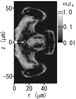
is shown in Fig. 6. The heat conduction is reduced by a factor of 1/{1+(ωeτe)2}. This factor could be as small
as 1/2 in the strong magnetic fields. Therefore, the self-generated magnetic field could play an important role in hot spark ignition.
5. Summary and Conclusion
Temporal evolution equations of self-generated mag-netic field are derived by including convection as well as the Nernst effect for imploding plasmas. We simulated magnetic filed generation in association with the Rayleigh-Taylor instability. The maximum magnetic field reaches 30 MG around the hot spark at maximum compression. The amplitudes of the magnetic field are estimated by the balance between amplification rate and diffusion. By this estimation, the magnetic field intensity is roughly obtained as B ≈ Teω2pe/(ecνei) ∝ Te2.5. Namely, B ≈ 30 MG at
maximum compression. Here, ωpe and νei are electron
plasma frequency and e-i collision frequency, respectively. If temperature increases as high as ignition temperature Te = 10 keV from Te = 5 keV which is the maximum
temperature of this simulation, the magnetic field increases 5-fold because the intensity of the magnetic field is propor-tional toTe2.5. Therefore, the peak magnetic field reaches
150 MG.
Since electron heat conduction is strongly affected by this magnetic field, the electron temperature profile is mod-ified and hydrodynamic motion may be strongly affected in burning plasmas.
The electron’s Lamor radius for a 30 MG magnetic field is estimated as rL 50µm, thus there exists the
possibility that particles may be trapped by the magnetic field. Therefore, the influence of the self-generated mag-netic field on ignition should be critically investigated. In three-dimensional simulations, stretching and dynamo ef-fects will appear to affect the magnetic field structure on an ablation surface. The three-dimensional effects will be important in this case and should be investigated in future studies.
Finally, we note that the strong magnetic field in the
Fig. 6 The distribution of the Hall parameterωeτe.
imploded plasma plays an extremely important role in rel-ativistic electron heating in fast ignition.
Therefore, the effects of a self-generated magnetic field on relativistic electron transport should also be inves-tigated in the future.
[1] J.A. Stamper, K. Papadopoulos, R.N. Sudan, S.O. Dean, E.A. McLean and J.M. Dawson, Phys. Rev. Lett.26, 1012 (1971).
[2] Y. Sakagami, H. Kawakami, S. Nagao and C. Yamanaka, Phys. Rev. Lett.42, 839 (1979).
[3] M. Tatarakiset al., Phys. Plasmas9, 2244 (2002). [4] C.E. Max, W.M. Manheimer and J.J. Thomson, Phys.
Flu-ids21, 128 (1978).
[5] P. Nicolai, M.Vandenboomgaerde, B. Canaud and F. Chaigneau, Phys. Plasmas7, 4250 (2000).
[6] T. Okada, T. Yabe and K. Niu, J. Phys. Soc. Jpn.43, 1042 (1977).
[7] T. Mochizuki, T. Yabe, K. Mima, K. Yoshikawa, H. Azechi, A. Kikuchi and C. Yamanaka, Jpn. J. Appl. Phys.19, L645 (1980).
[8] M.G. Haines, Phys. Rev. Lett.47, 917 (1981).
[10] K. Mima, T. Tajima and J.N. Leboeuf, Phys. Rev. Lett.41, 1715 (1978).
[11] A. Nishiguchi, T. Yabe and M. Haines, Phys. Fluids28, 3683 (1985).
[12] S.I. Braginskii,Reviews of Plasma Physics1(Consultants
Bereau, New York, 1965).
[13] H. Takabeet al., Phys. Fluids31, 2884 (1988).
![Fig. 3The contour profiles of (a)-(e):the electron density ne [cm−3], and (f)-(j):the electron temperature Te [eV] at t=3.9, 4.05, 4.13, 4.16, and 4.25 ns, respectively.](https://thumb-us.123doks.com/thumbv2/123dok_us/8447573.1703814/4.595.96.498.65.348/fig-contour-proles-electron-density-electron-temperature-respectively.webp)