Journal of Engineering Sciences, Volume 6, Issue 2 (2019), pp. D 9–D 13 D 9 JOURNAL OF ENGINEERING SCIENCES
ЖУРНАЛ ІНЖЕНЕРНИХ НАУК
ЖУРНАЛ ИНЖЕНЕРНЫХ НАУК
Web site: http://jes.sumdu.edu.ua DOI: 10.21272/jes.2019.6(2).d2 Volume 6, Issue 2 (2019)
Design Optimization and Simulation Analysis
of Formula SAE Frame Using Chromoly Steel
Kumar M. D.*, Teja P. S., Krishna R., Sreenivasan M.
PACE Institute of Technology and Sciences, 523 272 Ongole, Andhra Pradesh, India
Article info:
Paper received:
The final version of the paper received: Paper accepted online:
September 7, 2019 December 4, 2019 December 9, 2019
*Corresponding Author’s Address:
[email protected]
Abstract. Compliance with the rules and regulations of competition “Student Formula Car Racing” that conducted
annually by the ‘Society of Automotive Engineers’ (SAE) India, the car frame must be designed and built with su-preme priority. The major task posed is to design and fabricate a light weighed vehicle chassis frame without com-pensating the safety. This paper boards various methods of material selection, technical design optimization and Fi-nite Element Analysis using ANSYS. The basic design is based on the anthropological study data of the specified human (95th percentile male) al-lowing fast ‘way-in’ and ‘way-out’ access from the car. According to the rules book specification on material selection, AISI 4130 chromoly steel was the first time identified for the frame design. Re-sulting in the final design of the vehicle frame, various analyses were done using ANSYS and the successive results are plotted and discussed. The entire design optimization and simulation analysis are based on the 2019 Formula SAE rules book.
Keywords: finite element analysis, AISI 4130 chromoly steel, frame construction, Society of Automotive Engineers.
1
Introduction
The Formula SAE (FSAE) competition is a sponsor-ship contest held annually by the Society of Automotive Engineers (SAE), India from the period of 1998 to till date. Student teams from various engineering colleges all over India participate in this event, battle each other in car racing.
The teams are awarded points, based on different crite-ria of designing, fabricating and trail running the car. Basically, the criteria are based on the rulebook framed by SAE INDIA [1]. As per the rulebook, this paper exam-ines numerous traits of design of the vehicle frame, with an application emphasis to an open-wheeled, space-frame race car chassis, as used in Formula racing. The design is based upon considerations like load transfer through the structure, different deformation modes, stiffness of the frame in each deformation modes and its respective effect on the dynamic response of the car [2]. The model is designed and analyzed using Solid Works and ANSYS respectively and an optimum result was obtained. A tubu-lar frame structure was designed and analyzed, taking the specifications mentioned in the rule book into the concern for the design.
2
Research Methodology
2.1. Basic design
For designing a Formula SAE chassis frame, it is the following primary design parameter that always comes in the picture namely the suspension points, powertrain layout, driver position and controls and the safety aspects [3]. For the car to perform as intended, these parameters must be incorporated together to form an effective pack-age.
2.2 Suspension points
The suspension points are used to describe the co-ordinates for all other vehicle parts. Such points need to be defined and set in order to define the vehicle's remain-ing points. The suspension system preserves the vehicle's balance when the car is exposed to any of its axes at times.
2.3 Powertrain layout
D 10 MECHANICAL ENGINEERING: Dynamics and Strength of Machines
2.4 Driver position and controls
The driver alignment and controls are other important aspects of the chassis layout. Driver comfort considera-tions include seating orientation, room for the elbow, and head height in relation to the front of the car and activity controls.
2.5 Driver seating
The seating orientation was determined primarily by the driver, testing under different seatback angles in a plywood seat mockup. The angle between 45 and 50 degrees from horizontal was calculated to be optimal for a driver’s safety and comfort. The shallower seat position has a favorable impact by decreasing the driver's head and chest lower and the average center of gravity of the vehicle is therefore reduced [1]. With the driver’s head lower, it will be more difficult for short drivers to see over the front roll hoop and bulkhead. Nonetheless, as the contest driver of the team is between 5'6" and 5'8", the decision made to retain the shallow chair. Another benefit on 2019 rules on the cockpit space helps the driver to have more elbow room. This led to operating the steering wheel more effectively as the driver able to have more leverage in the cockpit.
2.6 Safety
The Rules committee developed a set of rules specify-ing tube sizes in areas of the frame, essential to driver safety. For the front bulkhead, front roll hoop, central roll hoop, side-impact piping, roll hoop bracing and front impact areas, these guidelines describe external diameters and wall thicknesses. Without exception, the specified rules are adhered, so that the driver can be protected and the vehicle can pass the practical examination in action.
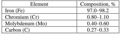
Table 1 – Chemical composition of chromoly steel
3
Materials
According to the constraint of the rulebook, the carbon content for the frame material should be at least 0.1 %. Following a comprehensive market survey, Chromoly Steel is the material commercially available and currently being used for an open-wheeled race car [5]. Based on that, this paper concludes on choosing AISI 4130 Chro-moly Steel as the material for the frame design.
3.1 Chromoly steel
Chromoly steel is a low-alloy steel type named after the addition of “chromium” and “molybdenum” – the two primary elements of the alloy composition. This class of steel identifies under the AISI 41xx designations. Chro-moly steel is typically an alloy steel grade 4130. The number 30 designates that material has 0.33 % carbon by weight. The inclusion of chromium and molybdenum
leads to better material properties in comparison to the mild steel containing the equivalent carbon content. The chromium contents lead to an increased material strength that renders it immune to rust, whereas the molybdenum increases toughness. Another advantage of AISI 4130 is the ability to be easily hardened by heat treatment or work hardening process. At an annealed condition AISI 4130 has greater formability, machinability and is quite easily weldable, which reduces the complexity of joining the frame parts. The physical properties and the chemical composition of the selected material are illus-trated in Table 1 and Table 2 respectively.
Table 2 – Properties of AISI 4130 chromoly steel
Density, kg/m3 7860.0
Ultimate tensile strength, MPa 520.0 Bending stress, MPa 1572.3 Young’s modulus, GPa 200.0
Shear modulus, GPa 80.0
Poisson’s ratio 0.29
The FSAE deck regulations involve a front and rear roll bar, side-impact frame, a front bulkhead and respec-tive supports for the above elements. Figure 1 displaying the simplest possible frame member configuration which contains the above described necessary components.
Figure 1 – Representation of frame members as per the rulebook
3.2 Side impact requirements
The lateral impact design includes two frame members and one diagonal member to avoid impact [1]. There is a 2-inch gap on both sides of the driver seat inside the cockpit. The upper side member is attached to the central hoop and 1000 mm from the surface is the maximum height of the roll hoop.
3.3 Consideration of frame design
Tools used: Solid Works and ANSYS. Tubular sec-tion, tube size: 25.0×1.2 mm (outer diameter × wall). Weight: 28 kg. Material: AISI 4130 (0.2–0.3 % of car-bon). Configuration: triangular (no bend pipe other than the main hoop and front hoop).
3.4 Frame construction
The frame comprises front and main hoops, shoulder harness line, side-impact protection, bracing and support for roll hoops, support for front bulkheads [6]. The chas-sis must be made of 95th percentile a male cockpit.
Figure 2 shows the vertical passage through the open-ing of the cockpit until it reaches the top bar of the lateral impact framework.
Element Composition, %
Iron (Fe) 97.0–98.2
Chromium (Cr) 0.80–1.10
Molybdenum (Mo) 0.40–0.60
Journal of Engineering Sciences, Volume 6, Issue 2 (2019), pp. D 9–D 13 D 11 Table 3 – Technical specification of the frame
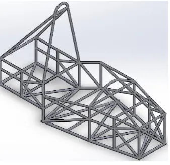
3.5 Frame modeling
The framework was designed to ensure maximum load path, space of different components and comply with regulations, considering the suspension points location [7]. The driver cell has ample space, offering storage for the gear lever, batteries, fuel tank, guaranteeing the safety of the operator and fast egress. 4130 Steel is used as it is an ideal material for the frame due to its machine durabil-ity, ease of manufacturing, tolerance to scaling and corro-sion, lean and smooth finish.
While the designing phase is carried out, the center of gravity of the car is concerned as a major objective keep-ing an eye on comfort and safety for the driver [8]. The seating level has been lowered to reduce the center of gravity of the car, keeping as low as possible, generating maximum downforce for greater traction and increased stability that the car should meet or even exceed safety standards. The analysis part is done using ANSYS (Fig-ures 2–6).
Figure 2 – Isometric view of chassis frame designed
4
Results and Discussion
4.1 Front impact test
Like any mechanical design, this chassis frame must be analyzed to determine whether it meets its goals of strength and rigidity. ANSYS tool is used for Finite Ele-ment Modelling and Analysis. BEAM-188 for the tubing and SOLID-187 for the engine are the component forms used in this study. BEAM-188 is based on the theory of Timoshenko beams and is used in slender beam design structure 1. SOLID-187 elements are tetrahedral 3D, 10-node elements used for nearly any solid part 2.
The important part of the text file is the description of the material and section properties for meshing. This also requires modeling of a-arms, pushrods, bell cranks, shocks and pivoting joints defined using key-points and lines.
The impact test is carried out, assuming the vehicle of mass 320 kg hits a static rigid wall at speed of 120 KMPH. The impact attenuator is made of foam absorbs all the impact load on collision happens for 0.3 S. As per calculation based on the impulse-momentum equation, deceleration of 10 g is assumed for the loading which is equivalent to a static force of 35.6 kN.
Boundary conditions: rear suspension mounts are clamped.
Figure 3 – Deformation during the front impact test
4.2 Side impact test
The fixed side-impact assessment is done, which is applied to the impact zone by adding a diagonal member as per rule book. Based on the calculation, deceleration of 6 g is assumed for loading that is equal to the static force of 18 kN. The vehicle’s mass is to be 320 kg at the total impact speed is 120 KMPH is assumed to hit on the de-signed vehicle of the same mass.
Boundary conditions: the right-side front and back ends of the suspension were clamped.
Figure 4 – Deformation during the side impact
Dimension Metric
Length, mm 2813
Width, mm 1455
Height, mm 1230
Track (front / rear), mm 1270 / 1321
Wheelbase, mm 1214
Car weight (with a passenger), kg 320
D 12 MECHANICAL ENGINEERING: Dynamics and Strength of Machines
4.3 Rear impact test
The rear impact test is carried out by assuming a Vehi-cle at speed of 120 KMPH having the mass of 320 kg hit the rear portion of the designed vehicle at stationary state. Boundary conditions: front suspension mounts are clamped.
Figure 5 – Deformation during a rear impact
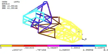
4.4 Torsional impact test
One of the most important tests validating the frame construction is torsional rigidity analysis. In this case, it is assumed that the chassis acts as a cantilever with the end of the rear suspension ends and the front suspension ends are fixed subject to equal and opposite torsional loads (couple) around its longitudinal axis. Boundary conditions: the force of 2.25 kN was loaded at each node.
The torsional stiffness K is calculated by the ratio of the torque T to the angle of rotation θ. The angle of rota-tion and torque are given by the following formulas:
θ = arctg(2a/L); T = mgL = 2Fw, (1)
where a – displacement; L – length; m – mass; g – gravity acceleration; F – force; w – force’s arm.
The stress, deformation, and factor of safety (FOS) for the respective tests were tabulated in Table 4.
From the above tabulation, it can be observed that the use of Chromoly material is more successful than the typical conventional frame material used in FSAE racing.
The tabulation further shows that the use of Chromoly reduces the vehicle self-weight, thus increasing the opti-mum performance by installing aero packages in the au-tomobile.
Figure 6 – Deformation during torsional stiffness
Table 4 – Test results
Test Stress, MPa Deformation FOS
Frontal impact test 114.6 2.39 4.5
Side impact test 87.3 0.73 5.2
Rear impact test 303.9 3.45 1.8
Torsional stiffness test 108.0 4.78 4.8
5
Conclusions
The conclusions of the work are as follows. Using Solid Works software, an ideal frame was designed for FSAE car racing. Specific parameters are analyzed for Chromoly Steel as the frame material using ANSYS for different tests according to the FSAE rule book. Based on the results, the chosen material was considered to be suit-able for the frame compared to conventional materials used.
References
1. Mohamad, M. L., Rahman, M. T. A., Khan, S. F., Basha, M. H., Adom, A. H., Hashim, M. S. M. (2017). Design and static structural analysis of a race car chassis for Formula Society of Automotive Engineers (FSAE) event. Journal of Physics: Con-ference Series, Vol. 908(1), article number 012042.
2. Yamanouchi, N., Ishii, K., Moriyama, H., Kato, H. (2019). Structural characteristics of the racing car in the student formula SAE competition. Proceedings of the School of engineering of Tokai University, Series E, Vol. 44, pp. 7–13.
3. Vasanthakumar, R., Manojkumar, P. R., Kesavaraj, M., Manikandan, G., Student, F. Y. U. (2019). Design and analysis of Formula-3 frame. International Journal of Engineering Science, article number 20840.
4. More, A., Chavan, C., Patil, N., Ravi, K. (2017). Design, analysis and optimization of space frame chassis. International Jour-nal of Engineering and Technology, Vol. 9(2), pp. 1411–1422.
5. Kamble, M., Shakfeh, T., Moheimani, R., Dalir, H. (2019). Optimization of a composite monocoque chassis for structural per-formance: a comprehensive approach. Journal of Failure Analysis and Prevention, Vol. 19(5), pp. 1252–1263.
6. Sethupathi, P. B., Chandradass, J., Sharma, A., Baliga, A. B., Sharma, S. (2018). Design and optimization of FSAE chassis us-ing FEA. IOP Conference Series: Materials Science and Engineering, Vol. 402(1), article number 012184.
Journal of Engineering Sciences, Volume 6, Issue 2 (2019), pp. D 9–D 13 D 13 8. Forrest, J. (2016). SAE Series Frame Design. Doctoral dissertation, University of Cincinnati, College of Engineering and
Ap-plied Science.
9. Thakar, P., Ail, S., Ranade, J. Mehta, P. (2019). Design, manufacture and testing of an impact attenuator for a FSAE car. Pro-ceedings of the International Conference on Intelligent Manufacturing and Automation, Springer, Singapore, pp. 151–159. 10.Krzikalla, D., Mesicek, J., Petru, J., Sliva, A., Smiraus, J. (2019). Analysis of torsional stiffness of the frame of a Formula
Stu-dent vehicle. Applied Mechanical Engineering, Vol. 7, pp. 315.
11.Sodisetty, V. N. B. P., Pandey, A., Iyer, D. B., Kumar, N. (2019). Torsional stiffness analysis of a tubular space-frame chassis.
SAE Technical Paper, No. 2019-28-0033.
12.Rahman, A., Rahman, M. T. A., Manaf, E. H. A., Rahman, A. S. A. (2018). Design and analysis of impact attenuator for a formula student car: A study between singular and bi-tubular tubes of varying geometries. IOP Conference Series: Materials Science and Engineering, Vol. 429(1), article number 012049.
13.Yang, L., Li, Q., Wang, C., Zhang, Y. (2017). Loads analysis and optimization of FSAE race car frame. SAE Technical Paper, No. 2017-01-0423.
14.Shukla, S., Agnihotri, S., Sahoo, R. R. (2016). Design and analysis of formula SAE chassis. Journal of Aeronautical and Au-tomotive Engineering, Vol. 3(1), pp. 26–32.
15.Bell, M. (2018). Development of a weight-saving carbon-fibre-reinforced polymer component for a FSAE race car. The UNSW Canberra at ADFA Journal of Undergraduate Engineering Research, Vol. 9(2).
16.Chandan, S. N., Sandeep, G. M., Vinayaka, N. (2016). Design, analysis and optimization of race car chassis for its structural performance. International Journal of Engineering Research and Technology, Vol. 5(7), pp. 361–367.
УДК 624.014
Оптимізаційний розрахунок конструкції автомобільної рами зі сталі 30ХМА
Кумар М. Д., Тея П. С., Крішна Р., Срінівасан М.Інститут технологій та наук ім. Пейс, 523 272, м. Онголе, Індія
Анотація. Відповідно до правил та правил змагань “Racing Formula Car Racing”, що проводиться щорічно товариством інженерів-автомобілістів (Індія), рама автомобіля повинна бути розроблена та побудована з най-вищим пріоритетом. Основним завданням є розробка та виготовлення легкої зваженої рами шасі автомобіля без втрати її надійності. У цій статті розглядаються різні методи вибору матеріалів та проведено процедуру оптимізаційного розрахунку конструкції рами на основі скінченноелементного аналізу за допомогою програ-много комплексу ANSYS. Базова конструкція обґрунтована даними антропологічного дослідження зазначе-ної людини (водія) автомобіля. Відповідно до існуючих рекомендацій щодо вибору матеріалу, хромо-молібденова стать 30ХМА була застосована для побудови рамної конструкції. У результаті, для остаточної конструкції рами транспортного засобу було виконано аналіз напружено-деформованого стану за допомогою програмного комплексу ANSYS, а отримані результати проаналізовані. Процедура оптимізаційного розраху-нку конструкції рами ґрунтується на загальних правилах SAE 2019.