Sensor solutions for an energy-efficient and
user-centered heating system
Moritz Hein1, Ralf Stöber1, Michael Meiler1, Daniel Schaller1, Rebecca Zehle1, Gerhard Fischerauer1, Jochen Bauer2, Johannes Bürner2, Jörg Franke2, Thomas Becher3, Martin Feller4, and Joachim Maul5
1Chair of Measurement and Control Systems and Center of Energy Technology (ZET), University of Bayreuth,
95440 Bayreuth, Germany
2Institute for Factory Automation and Production Systems, Friedrich-Alexander-Universität
Erlangen-Nürnberg, 91058 Erlangen, Germany 3TBE-Hof, 95028 Hof, Germany
4Frenzelit Werke GmbH, 95460 Bad Berneck, Germany 5ait-deutschland GmbH, 95359 Kasendorf, Germany
Correspondence to:Moritz Hein ([email protected])
Received: 30 September 2016 – Accepted: 19 December 2016 – Published: 23 January 2017
Abstract. In contrast to conventional hydronic heating systems, in which the air is used as a medium for the convective heat transfer, an alternative approach is based on the usage of infrared (IR) radiant heating foils. These foils, which are applied to the walls and the ceiling of a laboratory, can be controlled individually. This leads to the possibility of heating the room zonewise and only when a person is present in a zone. A local comfortable climate is provided only in occupied zones, with the remaining zones being kept at a lower base temperature. Consequently, the measurement system has to detect persons in each zone and to determine the putative thermal comfort at relevant locations in the room. For the first problem, we examined and evaluated different sensor types capable of localizing persons without infringing on their anonymity. For the second problem, we used the fact that the thermal comfort mainly depends on the operative temperature (Li et al., 2010; DIN EN ISO 7730, 2006; de Dear and Brager, 2002). According to Simone et al. (2007), this temperature can be measured directly by an easily producible, planar sensor. The sensors were integrated in a wireless sensor network which consists of Wi-Fi-capable microcontroller boards, wireless smart home equipment, a Wi-Fi router, and a server.
1 Introduction
The challenge when designing a heating system is that it should be as energy efficient as possible and yet must provide a comfortable room climate for the occupants and take their wishes and needs concerning the usage of the system into consideration (Hein et al., 2016a). These requirements have been addressed by Braun et al. (2016) by applying copper traces in the shape of a meander to the walls and supplying them with electrical energy. The system was operated in such a way that the surface temperature was about 28◦C, which was seemingly sufficient to provide a comfortable room cli-mate. There have been studies concerning the combination of heat pumps with photovoltaic systems (Brunner et al., 2016)
and even field trials with retrofitted heat pumps operated with high water temperatures (Shah and Hewitt, 2015). Crucial to such systems is the overall management of the various com-ponents, which needs to be intelligent at the data acquisition and control level (Chen et al., 2015; Fernandes et al., 2015).
By theoretical reasoning and by experiments, we ad-dressed the following issues:
– Which functional units are required to build a smart room climate control, and what is a suitable system ar-chitecture?
Heating
Electric power network Power
electronics
Zone 1 Zone 2
20 °C 22 °C
▲▼ ▲▼
Temperature sensor nodes Router
Radiator TRV
Heat pump openHAB server and
MQTT broker
HomeMatic CCU2
Localization units foils
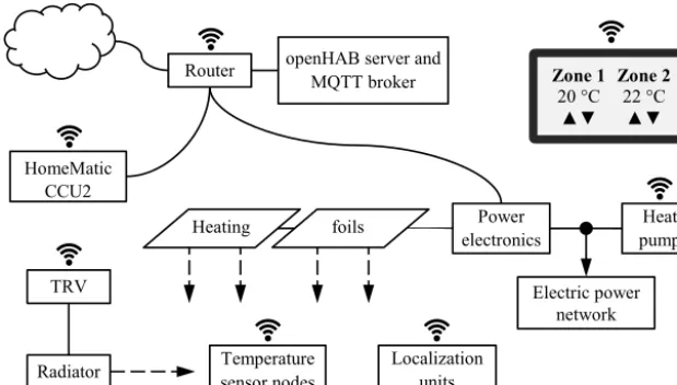
Figure 1.Heterogeneous architecture of the user-centered heating system. The communication is built around a Wi-Fi-capable router which is connected to the internet. The microcontrollers, which are used as temperature sensor nodes, as well as the controllers for the power electronics communicate via the resource-friendly message queue telemetry transport (MQTT) protocol. The HomeMatic components, like the thermostatic radiator valves (TRV), are accessible with the HomeMatic CCU2 Gateway. Users can interact through tablets, for instance; their commands, together with the sensor and actuator data, are stored and processed on the server and furthermore distributed in the network.
– What are the relevant deviations between the character-istics of the functional units and the physical units used to implement the functional-unit characteristics?
– How can the technical communication between the var-ious physical units of the heating system (sensors, heat-ing elements, controllers) be organized? The resultheat-ing system can be expected to be very heterogeneous, in-cluding different data formats and communication stan-dards.
2 Architecture
Because of the individual requirements of the inhabitants and the differing constraints of the buildings where the heating system will be built in, the overlaying management system should be as open and flexible as possible. In the past, smart home system providers offered vendor-dependent solutions and are recently trying to create vendor-specific alliances. In contrast to that, users prefer vendor independence because they want to add devices of all available providers, if those are relevant for their use cases. Therefore, a middleware sys-tem or an accepted standard is necessary. Currently, there are promising concepts for user-friendly middleware platforms, like openHAB, Eclipse-SmartHome, or Qivicon offered by Telekom, which share the same conceptual ideas regarding their technology stack. The framework used by us for the op-eration of the measuring and control system is openHAB 2, an open-source framework which has gained more and more attention in the scientific community (Smirek et al., 2016). As usual, for middleware platforms like openHAB, a user in-terface, device abstraction, and opportunities to use different
Figure 2.Simulation of the coefficient of performance (COP) of the combined heating system with the COP over the fraction of en-ergy provided by the heat pump (the remaining necessary enen-ergy is provided by the heating foils) and the outdoor temperature.
communication protocols are available. The openHAB sys-tem follows the OSGi specification, and therefore it is pos-sible to create plugins, called add-ons, which extend current functionality and can be enabled or disabled at runtime. One common use case for such an add-on is to add a translation layer for another communication protocol. In the openHAB ecosystem, those translators are called bindings. There are more than 100 bindings available (in openHAB), so lots of technologies can be used, i.e., online weather services, smart light bulbs, and a variety of communication protocols like KNX, Z-Wave, and Modbus.
The redevelopment of old building stock is feasible in dif-ferent ways. Obvious and widespread building measures are the exchange of the old windows by better insulated ones or the application of an additional layer of building insula-tion (BDEW, 2015). But there are buildings where such mea-sures are not applicable, e. g., listed buildings. Therefore, we have examined the combination of two heating technologies, which can be retrofitted in existing buildings, and the result-ing synergy. In this concept, the existresult-ing hydronic system is detached from the old source of heat (gas or oil burner) and equipped with a heat pump. To take advantage of the heat pump’s high coefficient of performance (COP), the amount of thermal energy provided by the heat pump is limited de-pending on the outdoor air temperature. The remaining share of energy is provided by infrared (IR)-radiant heating foils, which operate relatively independent of the weather condi-tions and are therefore on a constant level of performance. The simulation of this combined system, by varying the out-door temperature and the fraction of energy provided by each heat source, shows that there exists an optimum of operation at every temperature on the interval (Fig. 2). If the weather is mild, the heat pump drives the heating system exclusively. The colder it gets, the more energy is provided by the heating foils. With such a simulation, the performance of the heat-ing system is predictable for varyheat-ing annual average temper-atures in different regions.
The heating foils, which are powered by switching power supplies, are placed at the ceiling evenly and establish a com-fortable room climate where necessary. The fact that the heat-ing foils can be switched individually enables one to cate different temperature zones in a room. But this also re-quires solutions for a zone-wise measurement of the occu-pants’ thermal comfort and their location in the room. This measurement problem (selection of measurands, characteri-zation of individual sensors, heterogeneous integration into a control system) is the subject of this paper (Hein et al., 2016b) and the following sections.
2.2 Indoor localization
The localization of an occupant is crucial for a lot of smart home use cases. There are several strategies to obtain this kind of information, i.e., Bluetooth, RFID, infrared, or ul-trasonic sensors (Deak et al., 2012). In the context of user-centered heating scenarios, the following questions are rele-vant:
– Is it necessary to identify an occupant?
– Are camera-based solutions acceptable to occupants?
– Does a given solution measure precisely and accurately enough?
Figure 3.Signal processing for the thermopile array by dynamic masking (maskM) of the data points (matrixD). The maximum heat radiation was detected by pixeld2,2(yellow).
Table 1.Excerpt of the output data of an experiment with six per-sons; row and column of sensor pixels and the resulting presence (1) and absence (0) of persons in the field of view of the listed pixels.
Row Column Value (◦C) Presence
1 2 19.4 0
2 1 23.9 0
3 2 29.3 1
4 1 24.0 0
– Would an occupant agree to wearing some kind of de-vice?
– Are the installation costs economically justifiable?
– Is the installation possible in existing houses?
There exists a variety of sensors for the indoor localization of persons in a heating zone. Owing to privacy and accep-tance concerns (Arning and Ziefle, 2015), image generating and processing systems, like cameras, have been ruled out. Radiating sensors, like radar or ultrasonic sensors, would be suitable, but it is highly questionable in many societies, and certainly in Germany, whether users would accept them in the living room or in the bedroom.
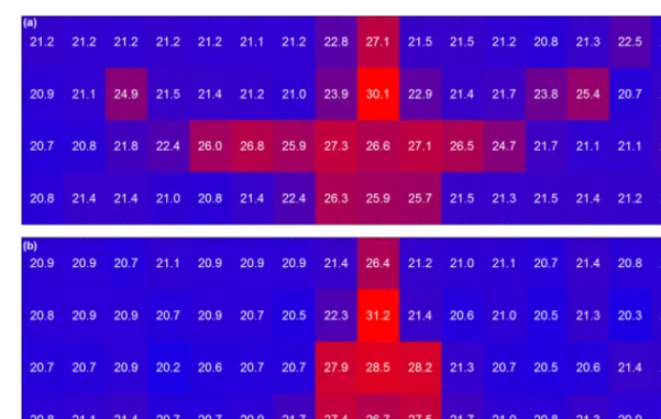
Figure 4.Output of the 4×4 thermopile array with(a)a sitting person and(b)a standing person. Measured temperatures are in◦C. The photos shown convey an idea of the scenarios the thermopile array was subjected to.
Figure 5.Experimental results with a 16×4 thermopile array pointed towards a person with(a)arms spread out and(b)arms at the sides of the body. Values are in◦C.
sensors were not investigated in more detail. For the experi-ments reported in the following, we used the thermopile ar-ray Omron D6T-44L-06 as an IR-radiation-based means of signaling the presence of persons in a heating zone.
A possible spatial distribution of the sensors for a maxi-mum field of view and a reliable detection has already been described in Kuki et al. (2013). Four sensors were arranged in a square configuration to obtain an 8×8 pixel resolution. On the assumption that a person fills up 3×3 pixels at most, the position was determined. So, for a precise localization within a room, several arrays are necessary. However, when one is mainly interested in the presence detection per heating zone, as we are, a single sensor suffices.
By analogy with image processing methods, the sensor output data are arranged in a 4×4 matrixDwhich resembles the sensor (thermopile array) structure. After that, the pix-els with minimum and maximum received IR radiation are identified as dmax=max di,j
and dmin=min di,j
with pixel temperaturesTmaxand respectivelyTmin. The algorithm
which decides whether a person is present or not is based on the following premises.
The determined maximumTmaxmust not be greater than 34◦C. No part of the human body has a higher surface tem-perature.
The determined minimumTminhas to be close to the en-veloping surface temperature; otherwise, no distinction be-tween the person and other heat-radiating objects can be made in the room.
To suppress random noise,Tmax−Tmin≥2◦C must apply. Finally, a 3×3 mask M is placed on the coordinates of dmax and the surrounding eight pixels, inheriting the tem-perature values ofDwithTmax atm0,0.Tmax is then com-pared to the surrounding values (Fig. 3). When the deviation is big enough, but not too big, the probability that a person is present rises. If the values of two or more pixels are on this temperature interval, a person is regarded as detected.
out-worked well even with a group of six people sitting in front of the sensor with a distance of 2 m, which was confirmed by a positive presence feedback in row 3 of Table 1.
Among the possible influencing effects are pets or other IR-radiating objects, such as a kettle. They could lead to a false positive presence detection and finally to the activation of the control loop. The sensitivity of the algorithm to such effects was characterized by experiments. It was found that the difference of the temperature of animal fur and the sur-face temperature of clothing is quite small. Only the tem-perature of the human skin of approximately 34◦C makes a significant difference to the surface fur temperature of 26◦C. Animals smaller than cats were not mistakenly detected as human beings. Cats and dogs with shorter fur, and therefore a higher surface temperature, on the other hand, were de-tected. Another situation in which the algorithm erroneously signaled the presence of a person was when animals were moving to or from the sensor. A dog with a height of 60 cm and very long fur, hence low surface temperature, caused false positives only rarely. Other disturbances like kettles, monitors, or even windows, which were warmed up by the insolation, did not lead to wrong alarms. Nonetheless, we ob-served that the algorithm only very rarely detected a (4-year old) child as a person.
In an attempt to increase the resolution, we examined the thermopile array Melexis MLX90621, which comprises 16×4 pixels. In contrast to the Omron D6T-44L-06, the higher resolution leads to the possibility to recognize a per-son’s shape (Fig. 5) and thus reduce the probability of false positives. Another advantage of the higher resolution is that the number of persons in a room can be determined. In com-parison to cameras, the resolution is low enough to maintain the occupants’ anonymity. Although the advantages of the thermopile arrays over PIR sensors are obvious, their higher purchase price is a major drawback in view of the fact that at least one sensor per room is needed. Our studies with com-mercial motion sensors (which use a PIR sensor internally) in an office show that the presence of persons who are working at their desks, even if practically at rest, is detectable.
2.3 Measurement of thermal comfort
The goal of a user-centered heating system is the occupants’ subjective sensation of heat or, in other words, their sense of thermal comfort. Consequently, this sensation has to be es-timated by a technically measurable quantity (Aswani et al., 2012). To this end, the predicted mean vote (PMV) has been established in the ISO standard 7730 (DIN EN ISO 7730, 2006). This standard has several drawbacks, e.g., the com-plex and only iteratively solvable calculation of the PMV and the dependency on poorly measurable quantities, such as the clothing level and the metabolic rate of a person. We therefore considered the operative temperature as a possible controlled variable. The comfortable operative temperature
( b) ( a)
Figure 6.Sensors investigated:(a)digital temperature and humid-ity meter Testo 480 with probes to measure the air temperature and humidity, the globe temperature (black copper sphere with a set-tling time of 20 min), and the air velocity;(b)sensor attached to a microcontroller board.
1 3
2
4
5
6
7
8 9 10
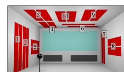
Figure 7.Arrangement of the heating foils in the demonstrator room (red). The black sphere marks the position of the globe ther-mometer or the single temperature sensor.
Tcomfis determined on the basis of the outdoor air tempera-ture (de Dear and Brager, 2002; Nicol and Humphreys, 2010) which should satisfy most of the occupants.Tcomf is calcu-lated as follows (Nicol and Humphreys, 2010):
Tcomf=0.331·Trm, (1)
whereTrmis the running mean temperature
Trm=0.2·Tdm−1+0.8·Trm−1. (2)
Here,Tdm−1andTrm−1are the previous-day values for the 24 h daily mean outdoor temperature and the running mean outdoor temperature. For outdoor temperatures below 10◦C, Tcomfis considered constant with a value of 22◦C.
The operative temperature can be determined by a climate-measuring instrument – we used the type Testo 480 – which comprises a probe for the air velocity, a globe thermometer, and an air thermometer. At a typical indoor air velocity of v≤0.1 m s−1, the operative temperatureTopis the arithmetic mean of the indoor air temperatureTaand the mean radiant temperatureTr:
Top=
1
0. 0 0. 5 22. 0 22. 5 23. 0 23. 5 24. 0
0 20 40 60
A bs olu te er ro r/ ° C T em per atu re/ ° C Time/min Sensor Operative temperature Absolute error
Figure 8.Step response of the various temperatures at a selected location in the demonstrator room after turning heating foil pair 1 on. 0. 0 0. 5 0. 0 0. 5 1. 0 1. 5 2. 0 2. 5 3. 0
0 20 40 60
Dev iatio n/ ° C Δ T/ ° C Time/min Case A Case B Case A + B Case C Deviation
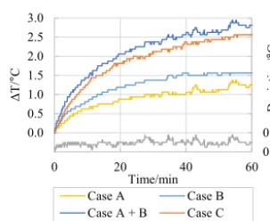
Figure 9.Comparison of the measured temperature changes in case A (pair 3 powered), in case B (pair 1 powered), and in case C (pairs 1 and 3 powered simultaneously). Also shown is the calculated sum of the results of cases A and B (“Case A+B”) and the deviation of this calculation from the measurement in case C.
Tr is calculated in the following manner according to ISO 7726 (ISO 7726, 1998):
Tr/◦C=
h
Tg/◦C+273
4
+k· Tg−Ta
/◦C
i0.25
−273, (4)
k=1.1·10
8· v/ m s−10.6
εg· dg/m
0.4 , (5)
with the globe, indoor air, and mean radiant temperaturesTg,
Ta, and Tr, respectively.v is the air velocity, andεg=0.95 anddg=0.15 m are the emission coefficient and the diame-ter of the globe thermomediame-ter, respectively.
As the climate-measuring instrument cannot be deployed in living spaces for size and cost reasons, we examined a round, planar temperature sensor with a diameter of 30 mm (Fig. 6) as suggested by Simone et al. (2007) as an al-ternative. Experiments in a room of approximately 40 m2 equipped with 10 pairs of heating foils (Fig. 7) showed that, at steady-state operation (constant temperature), such a sen-sor provides nearly the operative temperature calculated from the output values of the climate-measuring instrument. In dy-namic experiments, in which heating foils were turned on
-0. 5 -0. 4 -0. 3 -0. 2 -0. 1 21. 2 21. 4 21. 6 21. 8 22. 0 22. 2 22. 4 22. 6 22. 8
0 10 20 30
P re di ct ed me an vo te T em per atu re/ ° C Time/min Sensor Reference variable Predicted Mean Vote
Figure 10.Step responses of the operative temperature and of the PMV at a selected location in the demonstrator room in a closed-loop experiment with heating foil pairs 3 and 10 used as actuators.
Figure 11.Technology acceptance model (Davis et al., 1986).
and the resulting transient heating processes were monitored, the sensor reacted faster than the climate-measuring instru-ment, owing to its smaller thermal mass and therefore shorter settling time (Fig. 8). Another result of the dynamic experi-ments, also apparent in Fig. 8, is that the IR heating system has a time constant of 10 to 20 min. It is clear that such a sluggish behavior has to be taken into account in the design of the temperature feedback control.
This design is also influenced by the linear or nonlinear nature of the controlled system. We carried out experiments to determine if the combined action of several heating foils can be described by the sum of the actions of the individ-ual foils when operated alone (in other words, if the system can be treated as linear; the system is nonlinear, as shown by Eq. (4), but small temperature changes should warrant a linearization). This is indeed the case. For instance, the dif-ference between the added individual actions of two pairs of heating foils and their combined simultaneous action was less than 0.5◦C (Fig. 9). It follows that the whole system can be characterized by measuring the individual actions of the heating foils.
0 1
13,0 15,0 17,0 19,0 21,0 23,0 25,0
19.9.16 20.9.16 21.9.16 22.9.16 23.9.16 24.9.16 25.9.16 26.9.16
P
resen
ce
T
em
p
er
atu
re/
°C
Date
Temperature TRV
Operative temperature window Operative temperature desk Comfort temperature Presence desk
Figure 12. Time series of measured temperatures and occupant presence in a naturally ventilated office over a period of 7 days. The comfortable operative temperature was calculated from the measured values by Eq. (3).
increase the settling time of the feedback control system in comparison to the simple temperature sensor.
2.4 User interface
For the development of a new system, it is recommended to examine the acceptance or factors that increase the probabil-ity of use. In this context, acceptance is the positive reception of a chance a in physical environment after a deliberate ex-amination of the change that has taken place (Renn, 1986). In the focus of the technology acceptance model, according to Davis (1986), are the perceived benefit and the perceived usability. As shown in Fig. 11, these two factors influence the attitude directly and thus also the use of an innovation.
In addition to the perceived benefit of the system, the perceived usability is the second crucial factor for the ac-ceptance of a system. To ensure the usability, a human– machine interface (HMI), which is adapted to the needs of its users, has to be designed and implemented. The user char-acteristics, as well as the technical and physical environ-ment determine the context in which the system is applied (DIN EN ISO 9241, 2011). In former projects, our work-ing group established a well-proven development process for user interfaces which consists of focus group interviews, card sorting, and usability testing (Bauer et al., 2014a). OpenHAB offers the possibility to design such an optimized user inter-face which is accessible by smartphones or web browsers. If the inhabitants are not familiar with such technologies, open-HAB is flexible enough to embrace different solutions, like manual devices to set the desired temperature comparable to room thermostats.
3 Architecture implementation and evaluation
Our system has to comprise several temperature sensors, lo-calization units, and possibilities for the inhabitants to inter-act with the system. Through openHAB bindings, different technologies, like MQTT sensor nodes equipped with our op-erative temperature sensor, HomeMatic components, and the control unit of the heat pump, are interconnected via a Wi-Fi-capable router and managed by a small and energy-efficient PC. The PC is used as the central control unit (CCU) on which the openHAB server and a MQTT broker is running. The MQTT sensor nodes only send their measured values when the temperature change is bigger than 0.25◦C or after 5 min without a connection to the broker. This approach is necessary to reduce the overall network traffic and to extend the lifetimes of the sensor batteries. In addition, we deployed various wireless smart home equipment such as HomeMatic thermostatic radiator valves (TRVs), motion detectors, sen-sors which detect opened and closed windows, room ther-mostats, and an outdoor temperature sensor. These wireless sensors and actuators communicate with the BidCoS stan-dard via the HomeMatic CCU2. A subset of the incoming values are permanently stored in a time series database and thus are available for the calculation of the comfort tempera-ture or other processing at a later point in time.
window and the one on the desk (distance 3 m) is around 2◦C. The longer settling time of the TRV is also evident in comparison to the operative temperature sensor nodes, es-pecially when the room cooled down outside the working hours. In addition to the temperature progress, the measure-ments of the motion sensors were recorded. There is a clear distinction between the activity from 09:00 to 18:00 CEST and the rest of the day.
The digital controller is also implemented on the open-HAB framework. Every 30 s, the database is queried for the sensor and reference variable values, after which the con-troller output variables are calculated, and finally these vari-ables are sent to the actuators. The reference varivari-ables are calculated from the values of wireless thermostats where the user can adjust the desired temperature in each room or, op-tionally, by a web interface and a mobile app. Furthermore, the energy supplying company can influence the room tem-perature within the bounds of the comfort temtem-perature and with a lower priority than the user. This enables the supply-ing company to make use of load shiftsupply-ing and thus to use the available renewable energies more efficiently.
4 Discussion
We have analyzed the requirements of a smart heating system and, in particular, the necessary sensors and their integration in a feedback control system which relies on both wired and wireless communication. The system comprises temperature and localization sensors as measuring elements and heating foils as actuators. The latter were characterized experimen-tally, and the results of this characterization served to pa-rameterize a feedback controller with the so-called operative temperature as the controlled variable because it is an ac-cepted measure of thermal comfort. The system components were studied in a demonstrator room, and the entire hetero-geneous system has now been deployed in an apartment for further field studies during the heating season of 2016/2017. The localization of room occupants by thermopiles was shown to work reasonably well and is especially advanta-geous in terms of data security and user privacy. It does, how-ever, allow no personalization of heating services. With those users who wish such a personalization in mind, it needs to be analyzed if personal identification could and should be added to the current implementation. It would then be possible to create individual profiles of thermal comfort for each occu-pant of a building. A way of implementing such functionality could be via an occupant’s cell phone connected to the local home network.
Another possible extension of the demonstrator system could be to search the internet for relevant data to corroborate conclusions made by the system. An obvious choice would be to more consistently exploit weather forecasts. Such ap-proaches, often implemented by using web services or end-points, are promising strategies to benefit from the current
trend to digitalization, often referred to as Internet of Things (Bauer et al., 2014b).
5 Data availability
The corresponding data set is available at
doi:10.5281/zenodo.248977 (Hein et al., 2017).
Competing interests. The authors declare that they have no con-flict of interest.
Acknowledgement. The authors would like to express their sincere thanks to the Bavarian State Ministry of Education, Science and the Arts for partially funding the presented work within the E|Home-Center.
Edited by: E. Starke
Reviewed by: two anonymous referees
References
Arning, K. and Ziefle, M.: “Get that Camera Out of My House!” Conjoint Measurement of Preferences for Video-Based Health-care Monitoring Systems in Private and Public Places., 13th In-ternational Conference on Smart Homes and Health Telemat-ics, Geneva, 10–12 June 2015, 152–164, doi:10.1007/978-3-319-19312-0_13, 2015.
Aswani, A., Master, N., Taneja, J., Culler, D., and Tomlin, C.: Re-ducing Transient and Steady State Electricity Consumption in HVAC Using Learning-Based Model-Predictive Control, Proc. IEEE, 100, 240–253, doi:10.1109/JPROC.2011.2161242, 2012. Bauer, J., Kettschau, A., and Franke, J.: Optimierung der
Datenvisu-alisierung von AAL-Serviceplattformen durch Usability-Tests, 7. Deutscher AAL-Kongress, Berlin, 21–22 January 2014, 2014a. Bauer, J., Kettschau, A., Michl, M., Bürner, J., and Franke, J.: Die
intelligente Wohnung als Baustein im Internet der Dinge: Poten-zialanalyse und Konzept einer domänenübergreifenden Lösung, Conference Technische Unterstützungssysteme, die die Men-schen wirklich wollen, Hamburg, 15–16 December 2014, 12 pp., doi:10.13140/2.1.4173.0886, 2014b.
BDEW Bundesverband der Energie- und Wasserwirtschaft e. V.: Wie heizt Deutschland? – BDEW-Studie zum Heizungsmarkt, BDEW Bundesverband der Energie- und Wasserwirtschaft e. V., p. 28, 2015.
Braun, T., Bürner, J., Michl, M., Schaller, L., Böhm, R., and Franke, J.: Innovative Flexible Heating System by the Use of Additive Plasma Coating Technology– Heating Where Heat Is Needed by Additive Metallization of Furniture and Walls, 4th IEEE Interna-tional Conference on Smart Energy Grid Engineering, Oshawa, 21–24 August 2016, 278–283, 2016.
Domestic space heating energy control via Smart Home En-ergy Management. IEEE International Conference on Mecha-tronics and Automation, Beijing, 2–5 August 2015, 905–911, doi:10.1109/ICMA.2015.7237606, 2015.
Davis, F. D.: A Technology Acceptance Model for Empirically Test-ing New End-User Information Systems: Theory and Results, Cambridge, MIT Sloan School of Management, Massachusetts Institute of Technology, 24–26, 1986.
Deak, G., Curran, K., and Condell, J.: A survey of active and passive indoor localisation systems, Comput. Commun., 35, 1939–1954, doi:10.1016/j.comcom.2012.06.004, 2012.
de Dear, R. and Brager, G.: Thermal comfort in naturally ventilated buildings: revisions to ASHRAE Standard 55, Energ. Buildings, 34, 549–561, doi:10.1016/S0378-7788(02)00005-1, 2002. DIN EN ISO 7730:2006-05, Ergonomie der thermischen
Umge-bung – Analytische Bestimmung und Interpretation der thermis-chen Behaglichkeit durch Berechnung des PMV- und des PPD-Indexes und Kriterien der lokalen thermischen Behaglichkeit, DIN Deutsches Institut für Normung e.V., p. 6, 2006.
DIN EN ISO 9241-210:2011-01, Ergonomie der Mensch-System-Interaktion – Teil 210: Prozess zur Gestaltung gebrauch-stauglicher, interaktiver Systeme, DIN Deutsches Institut für Normung e.V., p. 14, 2011.
Fernandes, Fi., Carreiro, A., Morais, H., Vale, Z., Gastaldello, D. S., do Amaral, H. L. M., and Nunes de Souza, A.: Manage-ment of Heating, Ventilation and Air Conditioning system for SHIM platform. IEEE PES Innovative Smart Grid Technolo-gies Latin America, Montevideo, 5–7 October 2015, 275–280, doi:10.1109/ISGT-LA.2015.7381167, 2015.
Hein, M., Stöber, R., Fischerauer, G., Bauer, J., Bürner, J., Kettschau, A., Franke, J., and Feller, M.: Heating system to pro-vide a comfortable indoor climate and to reduce negative ef-fects on health in old buildings, Zukunft Lebensräume Kongress, Frankfurt a. M., 20–21 April 2016, 102–108, 2016a.
Hein, M., Stöber, R., Zehle, R., Meiler, M., Schaller, D., Fischer-auer, G., and Feller, M.: Sensorlösungen für eine energieef-fiziente nutzerzentrierte Heizung, Tagungsbd. 18. GMA/ITG-Fachtagung Sensoren und Messsysteme, Nürnberg, 10–11 May 2016, 663–668, doi:10.5162/sensoren2016/P5.7, 2016b.
tions for an energy-efficient and user-centered heating system, doi:10.5281/zenodo.248977, 2017.
ISO 7726:1998, Ergonomics of the thermal environment – instru-ments for measuring physical quantities, International Organiza-tion for StandardizaOrganiza-tion, Geneva, Switzerland, p. 19, 1998. Kuki, M., Nakajima, H., Tsuchiya, N., Kuramoto, K., Kobashi, S.,
and Hata, Y.: Mining Multi Human Locations Using Thermopile Array Sensors, IEEE 43rd International Symposium on Multiple-Valued Logic, Toyama, 59–64, doi:10.1109/ISMVL.2013.38, 2013.
Li, B., Li, W., Liu, H., Yao, R., Tan, M., Jing, S., and Ma, X.: Physi-ological Expression of Human Thermal Comfort to Indoor Oper-ative Temperature in the Non-HVAC Environment, Indoor Built Environ., 19, 221–229, doi:10.1177/1420326X10365213, 2010. Nicol, F. and Humphreys, M.: Derivation of the adaptive
equations for thermal comfort in free-running buildings in European standard EN15251, Build. Environ., 45, 11–17, doi:10.1016/j.buildenv.2008.12.013, 2010.
openHAB – Supported Technologies, availabe at: http://www. openhab.org/features/supported-technologies.html, last access: 5 January 2017.
Renn, O.: Akzeptanzforschung: Technik in der gesellschaftlichen Auseinandersetzung, Chemie in unserer Zeit, 20, 44–52, 1986. Shah, N. and Hewitt, N.: High temperature heat pump operational
experience as a retrofit technology in domestic sector. IEEE In-ternational Conference on Engineering, Technology and Innova-tion/International Technology Management Conference, Belfast, 7 pp., doi:10.1109/ICE.2015.7438691, 22–24 June 2015. Simone, A., Babiak, J., Bullo, M., Landkilde, G., and Olesen, B.
W.: Operative temperature control of radiant surface heating and cooling systems, Proc. 9th REHVA World Congress Clima 2007 “WellBeing Indoors”, Helsinki, 8 pp., 10–14 June 2007. Smirek, L., Zimmermann, G., and Beigl, M.: Just a Smart