www.mech-sci.net/4/251/2013/ doi:10.5194/ms-4-251-2013
©Author(s) 2013. CC Attribution 3.0 License.
Mechanical
Sciences
Open AccessGantry crane control of a double-pendulum,
distributed-mass load, using mechanical wave concepts
W. O’Connor and H. Habibi
UCD School of Mechanical and Materials Engineering, UCD Belfield, Dublin 4, Ireland
Correspondence to: H. Habibi ([email protected])
Received: 15 November 2012 – Revised: 16 April 2013 – Accepted: 19 April 2013 – Published: 1 July 2013
Abstract. The overhead trolley of a gantry crane can be moved in two directions in the plane. The trolley is attempting to control the motion of a suspended, rigid-body, distributed mass load, supported by a hook, modelled as a lumped mass, in turn connected to the trolley by a light flexible cable. This flexible system has six degrees of freedom, four variables describing the flexible, hanging load dynamics and two (directly controlled) input variables for the trolley position. The equations of motion are developed and the crane model is verified. Then a form of wave-based control (WBC) is applied to determine what trolley motion should be used to achieve a reference motion of the load, with minimum swing during complex manoeuvres. Despite the trolley’s limited control authority over the complex, flexible 3-D dynamics, WBC enables the trolley to achieve very good motion control of the load, in a simple, robust and rapid way, using little sensor information, with all measurements taken at or close to the trolley.
1 Introduction
In a typical problem of crane control, the challenge is to achieve controlled motion of the load, simultaneously mov-ing it to follow a desired trajectory while actively controllmov-ing the swing. The system can be described as under-actuated: only the trolley is directly controlled, and it must indirectly control the swinging load at the far end of the cable. Perfor-mance can be measured under various headings, including minimization of sway during motion or on arrival at target, tracking desired motion paths, accurate repositioning pay-loads in target within the shortest possible time, maximum repetition rate, and safety (Abdel-Rahman et al., 2003). Even with no external disturbances, the trolley motion can cause significant payload pendulation, especially when the dynam-ics are more complex. Also cranes are inherently lightly damped (Todd et al., 1997). Finally, the load can change sig-nificantly, in ways which the controller may not know in ad-vance. All these factors add to the control challenge.
Experienced crane drivers can acquire considerable skill, both in steering a load along a desired trajectory and in damp-ing the swdamp-ingdamp-ing, especially on arrival at target. The trajec-tory might require guiding a heavy load safely around or
tween obstacles, within a factory, on a building site, or be-tween a dock and a ship’s hold. But developing the driving skills takes time and is expensive. Also even highly trained drivers can make mistakes. Furthermore drivers will typically err on the side of safety at the cost of longer manoeuvre times. Often drivers will also rely on at least one assistant (a person) to guide the load, especially for final positioning. One view of improving automatic control, therefore, is to try to understand what experienced crane drivers do intuitively, defining when to accelerate and to decelerate, and for pla-nar trolleys, where and when to change direction and how quickly. But fully understanding what a human operator does is far from easy, and implementing this in a robust automatic control system is a further challenge.
252 W. O’Connor and H. Habibi: Gantry crane control of a double-pendulum
The reference inputs are requested motions to the system, that is, desired controlled motions of the load. These in-puts could be desired crane positions or velocities over time. (Specifying one, of course, implicitly specifies the other.) Here it is assumed that the reference inputs are position con-trol requests for the load motion over time. Often the problem is one of getting the load to track a desired trajectory. Many papers measure performance by the tracking ability of their control strategies (Sun et al., 2013; Kim and Singhose, 2010; Manning et al., 2010; Neupert et al., 2010; Forest et al., 2001; Vaughan et al., 2011).
In published work to date, the load and cable dynamics are frequently modelled as a simple or (at most) a double pendu-lum system moving in a plane. Abdel-Rahman et al. (2003) in a crane review article report that “most control strategies for this class of crane assume a planar gantry crane, utilize planar, linear models, and assume that the crane path, ex-ternal forces, and control effort are all planar”. The simple pendulum model considerably simplifies the dynamics, giv-ing a swgiv-ing frequency which is independent of the load mass. The simplification is not always appropriate however. Some researchers have recently modelled the loads as 3-D pen-dula to which various control techniques have been applied. However they generally assume a single, lumped-mass, load (Al-Garni et al., 1995; Sun et al., 2013; August et al., 2010; Yang and Yang, 2006; Anti´c et al., 2012; Cheng-Yuan et al., 2006; Maghsoudi et al., 2012; Chen et al., 2005; Schulze and Chang, 2010; Zhong, 2011). The most dynamically advanced developments in crane controllers in 3-D assume point mass loads, or at most, a rod-like body hanging from the trolley.
Some papers report work on controlling double-pendulum cranes (Kim and Singhose, 2006; Kim and Singhose, 2010; Masoud and Nayfeh, 2003; Sawodny et al., 2002; Manning et al., 2010; Tanaka and Kouno, 1998; Cheng-jun et al., 2009; Singhose and Towel, 1998; Kenison and Singhose, 1999; Dan and Li, 2008) but their simulations or experiments are planar rather than spatial. Manning et al. (2010), for example, present a dynamic model of bridge cranes with distributed-mass loads as a planar double pendulum. This work is an example of the use of input shapers. In general, the input shaper design depends on knowing the natural frequencies of the flexible system to be controlled. See Kenison and Singhose (1999) for example.
The authors found no research which considered the con-trol of a 3-D double-pendulum crane involving rigid body dy-namics, so this aspect of the work is considered novel. Also novel is the application of wave ideas to this control problem, although it had previously been applied to a simple, one-degree of freedom gantry crane leading to a robust control performance (O’Connor, 2003). In this work it is shown that “wave-based control”, or WBC, can be applied successfully to controlling more complex dynamical systems in 3-D, such as controlling the double-pendulum load, retaining many of the advantages that WBC demonstrated in controlling sim-pler systems.
The paper treats the load as a distributed mass, with trans-lational and swing rotational inertia effects about two axes. Furthermore, this distributed load is assumed to be hanging from a hook of significant mass, about which the load is free to swing. The hook in turn is modeled as a lumped mass, so that its 3-D translational inertia effects can be taken into ac-count. The trolley is taken to move in the horizontal plane, with motion controllers for two perpendicular axes. Three simplifying assumptions or restrictions are made. Firstly, the effects of cable hoisting are not considered. Secondly, the mass of the cable is assumed to be negligible. Thirdly, spin rotation of the load (as opposed to swinging in either pla-nar direction) is neglected. (The authors are confident that WBC can easily be adapted to work without these assump-tions, but the present paper assumes them to make the flex-ible dynamics more manageable.) The entire system has 6 degrees of freedom, four of which are determined by the sys-tem dynamics and two of which are controlled, input vari-ables. Figure 1 shows a schematic of the system model and the variables used as coordinates in the dynamic model.
As a control technique, WBC has been successfully ap-plied to various flexible mechanical systems. It sees the ac-tuator motion (in this case the motion of the trolley) as launching a disturbance, or mechanical wave, into the flex-ible system, while responding to waves coming back from the system, usually trying to absorb them (O’Connor, 2003, 2007; O’Connor et al., 2009; O’Connor and Fumagalli, 2009; O’Connor and McKeown, 2008; McKeown, 2009). This launching and absorbing are considered to be happening si-multaneously. These notional motion waves have DC com-ponents (or net displacement comcom-ponents), which, on pass-ing thought the flexible system, from actuator to tip and back again, leave behind the desired net displacement, while si-multaneously controlling vibrations. The control system de-cides on the launch wave net displacement, usually setting it to half the reference displacement. The returning motion wave from the system is measured and is added to the launch wave, and this combination forms the input to the trolley mo-tion controllers.
Fig.1: Representation of the 3D double pendulum gantry crane
X1
Y1
Z1
G m1 (hook) l1
l2 ,m2
θ2y θ2x
θ1x
θ1y
Trolley
Cable X2
Y2 Z2 X o Y Z
Figure 1.Representation of the 3-D double pendulum gantry crane.
2 3-D model of system dynamics
Figure 1 represents the entire physical system as modeled, including trolley, rails, cable, hook and hanging rigid body payload.
The trolley can move in both x and y directions simulta-neously, so that it can follow an arbitrary path in the X−Y
plane in response to input signals to the trolley position sub-controllers. The reference system with coordinates X1Y1Z1
is attached to the trolley, with Z1vertically downwards. The
hook is connected to the trolley by a light, flexible cable, with the cable mass considered negligible in comparison with that of the hook and the load. The hook is modeled as a point mass (m1), the kinetic energy of which is therefore purely
translational. Also since cable hoisting is ignored, the cable length is taken as a constant, l1, so the exact position of the
hook can be determined by the angle of the cable in space. This angle is measured by two variables,θ1xandθ1y, which
are the projections of the cable onto the X−Z plane and Y−Z
planes, respectively. A second reference frame with coordi-nates system X2Y2Z2, parallel to the first, has its origin at the hook, and is used to describe the swing rotation of the load, again using two angles,θ2xandθ2y, which are projections of the load angle onto the X−Z and Y−Z planes, respectively.
The instantaneous location of hook with respect to an in-ertial (space) coordinate system is given by
xH=xT+l1sinθ1x
yH=yT+l1cosθ1xsinθ1y
zH=l1cosθ1xcosθ1y
(1)
where xTand yTare the trolley’s position in the inertial
refer-ence frame. The position of the mass centre, G, of the swing-ing load is given by
xG=xT+l1sinθ1x+l22sinθ2x
yG=yT+l1cosθ1xsinθ1y+l22cosθ2xsinθ2y
zG=l1cosθ1xcosθ1y+l22cosθ2xcosθ2y
(2)
The equations of motion are obtained from Lagrange’s equa-tion
d dt
∂L ∂˙qi !
− ∂L
∂qi !
=0 (3)
The generalized coordinates, qi, are here taken as the four
in-dependent variablesθ1x,θ1y,θ2xandθ2y. The trolley position variables xT and yT are considered as input variables, used
to control the attached flexible system, so four equations of motion are required. If m1is the mass of the hook and m2the
mass of the load, total potential energy is
U=m1gl1
1−cosθ1xcosθ1y
+m2g
"
l1
1−cosθ1xcosθ1y
+l2
2(1−cosθ2xcosθ2y)
#
(4)
where g is the acceleration due to gravity. The total kinetic energy may describe as
T=1
2m1
*
vH
*
vH+
1 2m2
*
vG
*
vG+
1
2ω˜[IG] ˜ω (5)
where*vHis the hook velocity,
*
vGis the velocity of point G,
and ˜ω is the total angular velocity of the load. The linear velocities are the derivatives of Eqs. (1) and (2), which may be expressed in the form
*
vH:
˙xH=˙xT+l1θ1x˙ cosθ1x
˙yH=˙yT−l1θ1x˙ sinθ1xsinθ1y+l1θ1y˙ cosθ1xcosθ1y
˙zH=−l1θ1x˙ sinθ1xcosθ1y−l1θ1y˙ cosθ1xsinθ1y
(6)
*
vG:
˙xG=˙xH+l22θ2x˙ cosθ2x
˙yG=˙yH−l22θ2x˙ sinθ2xsinθ2y+l22θ2y˙ cosθ2xcosθ2y
˙zG=˙zH−l22θ2x˙ sinθ2xcosθ2y−l22θ2y˙ cosθ2xsinθ2y
(7)
To quantify the rotational kinetic energy of the load requires its angular velocity ˜ωand moment of inertia tensor, [IG], to
be expressed in a common coordinate system. The load in-ertia tensor is most conveniently expressed using a coordi-nate system X2cY2cZ2cfixed to the load and along its principal axes, so that
[IG]=
Ixx 0 0
0 Iyy 0
0 0 Izz
X2cY2cZ2c
(8)
254 W. O’Connor and H. Habibi: Gantry crane control of a double-pendulum
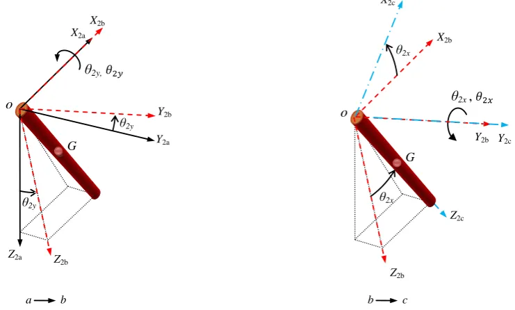
Fig.2: Representation of successive rotations to reach the body coordinates of the hanging load
Figure 4: WBC plan for gantry crane with planar-moving trolley
X
F x
F y
o X-Returning Wave Y-Returning Wave ½ + + ½ + + X-reference Y-reference Fx Fy xT yT Trolley bx by
Actual trolley motion [x, y]T
Reference actuator motion [x, y]Ref
o Y Actuator Y2b θ2y, θ2y θ2y X2a X2b Y2a Z2b Z2a X2b Z2b Y2b Z2c o o θ2x θ2x Y2c G G
a b b c
X2c
θ2x ,
Figure 2.Representation of successive rotations to reach the body coordinates of the hanging load.
moves through two rotations about the main axes to become aligned to the load body axis X2cY2cZ2c. The angular velocity
( ˜ω) according to Fig. 2 is defined as
˜
ω=−θ2y˙ ˆi2b+θ2x˙ ˆj2c (9)
The transformation from X2bY2bZ2bto X2cY2cZ2cor T2b→2c
is
T(2b→2c)=
cosθ2x 0 −sinθ2x
0 1 0
sinθ2x 0 cosθ2x
(10)
So finally ˜ωcan be expressed in X2cY2cZ2cas
˜ ω=
−θ2y˙ cosθ2x ˙
θ2x
−θ2y˙ sinθ2x
X2cY2cZ2c
(11)
The rotational kinetic energy of the hanging load, Tω, is then
expressible as
Tω=1
2ω˜[IG] ˜ω= 1 2Ixx(˙θ2y)
2
(cosθ2x)2+
1 2Iyy(˙θ2x)
2
+1
2Izz(˙θ2y)
2
(sinθ2x)2 (12)
Substituting Eqs. (6), (7) and (12) into Eq. (5) gives the total kinetic energy of system. Then this T from Eq. (5) minus U from Eq. (4) gives the Lagrangian, L=T−U to be used in
Eq. (3), with qiequal, in turn, to each of the four anglesθ1x,
θ1y,θ2xandθ2y, giving four equations of motion, which after
simplification become
m1l21+m2l21θ1x¨ +(m1+m2) l1¨xTcosθ1x−(m1+m2) l1¨yT
sinθ1xsinθ1y+(m1+m2)l21(˙θ1y) 2
cosθ1xsinθ1x+1
2m2l1l2θ2x¨
cosθ1xcosθ2x−
1
2m2l1l2(˙θ2x)
2
cosθ1xsinθ2x+
1 2m2l1l2
¨
θ2x
sinθ1xsinθ2xcos (θ1y−θ2y)+1
2m2l1l2(˙θ2x)
2
+(˙θ2y)2sinθ1x
cosθ2xcos (θ2y−θ1y)+1
2m2l1l2θ2y¨ sinθ1xcosθ2xsin
θ2y−θ1y
+m2l1l2θ2x˙ θ2y˙ sinθ1xsinθ2xsinθ1y−θ2y+(m1+m2) gl1
sinθ1xcosθ1y=0 (13)
(m1+m2) l21(cosθ1x)2θ¨1y−2 (m1+m2) l21θ˙1xθ˙1ysinθ1xcosθ1x
+(m1+m2) l1¨yTcosθ1xcosθ1y+
1
2m2l1l2θ2y¨ cosθ1xcosθ2x
cos (θ1y−θ2y)+1 2m2l1l2
˙
θ2x2
+˙
θ2y2
cosθ1xcosθ2x
sinθ1y−θ2y
+1
2m2l1l2 ¨
θ2xcosθ1xsinθ2xsin
θ1y−θ2y
−m2l1l2θ2x˙ θ2y˙ cosθ1xsinθ2xcos (θ1y−θ2y)+(m1+m2)
Figure 3.Dynamic response of 3-D double pendulum gantry crane with 4 degree of freedom.
m2
l2 2
4 +Iyy
¨
θ2x+1
2m2l2¨xTcosθ2x− 1
2m2l2¨yTsinθ2x
sinθ2y+1
2m2l1l2θ1x¨ cosθ1xcosθ2x− 1
2m2l1l2(˙θ1x)
2
sinθ1xcosθ2x+
1 2m2l1l2
¨
θ1xsinθ1xsinθ2xcos
θ1y−θ2y
+1
2m2l1l2
˙
θ1x2
+
˙
θ1y2
cosθ1xsinθ2xcos(θ1y−θ2y)+1 2
m2l1l2θ¨1ycosθ1xsinθ2xsin (θ1y−θ2y)−m2l1l2θ˙1yθ˙1xsinθ1x
sinθ2xsinθ1y −θ2y+m2l 2 2
4
˙
θ2y2
cosθ2xsinθ2x+(Ixx−Izz)
˙
θ2y
2
cosθ2xsinθ2x+m2g l2
2sinθ2xcosθ2y=0 (15)
m2
l2 2
4(cosθ2x)
2+
Ixx(cosθ2x)2+Izz(sinθ2x)2
¨
θ2y−m2l 2 2
2θ2x˙ θ2y˙
cosθ2xsinθ2x+1
2m2l2¨yTcosθ2xcosθ2y+ 1
2m2l1l2θ1x¨ sinθ1x
cosθ2xsin (θ2y−θ1y)+1 2m2l1l2
˙
θ1x2
+˙
θ1y2
cosθ1xcos
θ2xsin (θ2y−θ1y)+1
2m2l1l2θ1y¨ cosθ1xcosθ2xcos (θ1y−θ2y) −m2l1l2θ˙1xθ˙1ysinθ1xcosθ2xcos (θ2y−θ1y)+(Izz−Ixx)
˙
θ2xθ2y˙ sin (2θ2x)+m2l2
2g cosθ2xsinθ2y=0 (16)
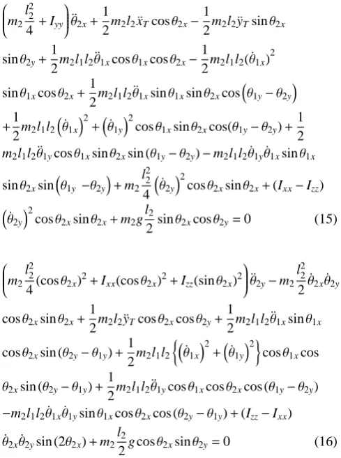
These four, highly coupled, equations of motion capture the full system dynamics. In the modeling, no small-angle ap-proximations were made to keep the model accurate even for large swing angles. These four equations can be integrated numerically from given initial conditions to describe the time evolution of the system. The trolley motion components are considered as inputs, defining ¨xT and ¨yT in these equations.
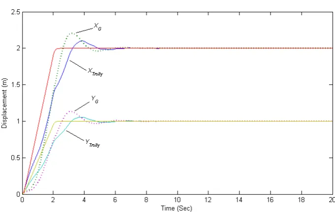
As an example, Fig. 3 shows the behavior of the system for an arbitrary planar movement of the trolley with no damping
Table 1.Values chosen for the 3-D double pendulum system.
m1(kg) m2(kg) l1(m) l2(m)
1 50 1 2
or control action. The chosen system parameters (which can be arbitrarily chosen) are given in Table 1.
While the input motion of the trolley takes no longer than two seconds, the system keeps swinging indefinitely, with multiple frequency components. Alternatively, rather than by trolley motion, the system can be set in motion by giving it initial angular displacements and/or velocities, with the trol-ley stationary. If desired this can be done in such a way that the subsequent motion corresponds to the mode shapes, at each of four natural frequencies.
With the crane model behaving as expected, the WBC ideas are now developed and used to control the swinging load by controlling the trolley motion.
3 Wave-based approach to crane control
From a control perspective, the trolley is a single actuator attempting to control a flexible system of relatively complex dynamics. The system is under-actuated, with more degrees of freedom than actuators. The actuator does not act directly on the load position and orientation, but must work through the intervening flexible dynamics, of cable and hook, to try to achieve a target motion of the load. The actuator motion is in two perpendicular directions, the load can swing in 3-D, and the motion components are strongly coupled.
256 W. O’Connor and H. Habibi: Gantry crane control of a double-pendulum
Fig.2: Representation of successive rotations to reach the body coordinates of the hanging load
Figure 4: WBC plan for gantry crane with planar-moving trolley
X
F x
F y
o X-Returning Wave Y-Returning Wave ½ + + ½ + + X-reference Y-reference Fx Fy xT yT Trolley bx by
Actual trolley motion [x, y]T
Reference actuator motion [x, y]Ref
o Y Actuator Y2b
θ
2y, θ2y θ2y X2a X2b Y2a Z2b Z2a X2b Z2b Y2b Z2co
o
θ2x θ2x Y2c G Ga b b c
X2c
θ
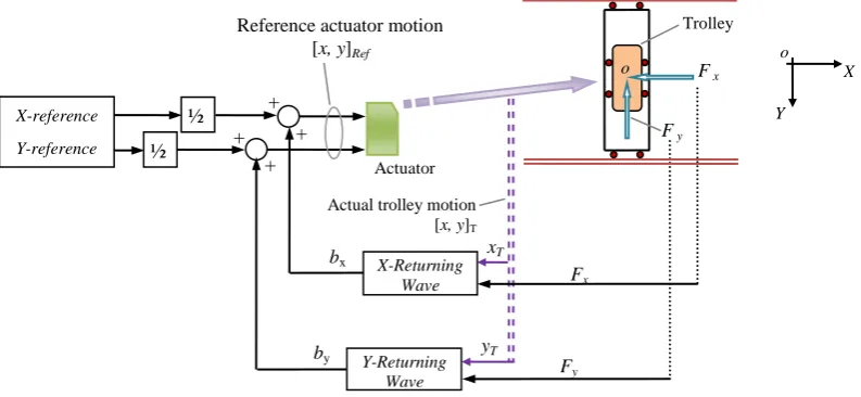
2x ,Figure 4.WBC plan for gantry crane with planar-moving trolley.
the consequent stability advantages. To date WBC has been used successfully to control 1-D rectilinear lumped flexible systems, 2-D flexible mass-spring arrays either beam-like or arranged in a grid, laterally flexing manipulators, and a sim-ple pendulum gantry crane as already mentioned (O’Connor, 2003).
In the current case, there are two inputs actuating the trol-ley motion in two orthogonal directions. So the troltrol-ley should be given two reference displacements, in the x and y direc-tions, and two corresponding returning waves, bxand by, to
achieve wave absorption in the two directions under WBC. Figure 4 illustrates a version of a general scheme for posi-tioning the trolley, along with the payload, to a target position in the plane.
Here the returning displacement waves are defined and measured as
bx=
1 2
xT−
1
Zx t Z
0 Fxdt
(17)
by=
1 2
yT−
1
Zy t Z
0 Fydt
(18)
where xTand yT are the trolley position coordinates, Fxand
Fyare the horizontal components in the x and y directions
of the cable force measured at the trolley, and Zx, Zy are
impedance terms. References O’Connor (2003) and McKe-own (2009) outline how such expressions for the returning waves can be developed. Here we simply note the following two features.
First, for rest-to-rest motion, from time t=0 to some final time t, as the initial and final momenta are zero, the force integrals must be zero. So the final values of bxand bywill be
half the trolley displacements, or 1/2xT and 1/2yT. Note that
this result holds regardless of the values of the impedances
Zxand Zy. The second observation is that while Fxand Fy
are changing, the effect of adding bx and byto the trolley’s
motion is to make the trolley act as a viscous damper with damping coefficient Zx, Zyin response to the cable forces.
The values of impedance are not critical to the control scheme. In this work both impedances were set to
Z=(m1+m2)
r g
(l1+l2)
(19)
Variations in the values of Z cause small variations in the transient part of the responses. So Z can be used as a pa-rameter with which to fine-tune the transient, for example to improve a specific performance measure (e.g. rise time, overshoot, or settling time), as appropriate for a given ap-plication, invariably at the cost of a slight degradation of some other transient performance measure (although always retaining the zero steady-state error).
The force components Fx and Fy should ideally
corre-spond to the horizontal components of the cable tension, in-cluding the dynamic effects of the acceleration of the load mass. For most purposes, however, they can be approximated by assuming that the cable tension is equal to the load weight, and then Fxand Fyfrom Fig.1 can be taken as
Fx=
−(m1+m2) g tanθ1x
cosθ1y (20)
Fy=−(m1+m2)g tanθ1y (21)
Figure 5.Gantry crane response to a 1 m displacement in x direction using WBC.
Figure 6.Response to planar trolley motion under WBC (sub G: mass centre of distributed load).
4 Results
In the first manoeuvre the reference is a simple ramp (or con-stant velocity) displacement of one meter in the x direction, with no motion in the y direction. Figure 5 depicts the re-sponse of both the trolley and the centre of mass of the pay-load, G, under the control system of Fig. 4. Also the swinging angles of the cable (in both directions) and of the load due to this excitation are displayed in radians. The trolley can be seen to settle quickly at the target displacement with an ini-tial overshoot of less than 10 %. The centre of mass of the hanging load, at 2 m from the trolley, comes to rest rapidly, with little swing as shown byθ1xandθ2x, and with an over-shoot of about 10 %. Clearly the suspension swinging dies out soon after the trolley reaches the target. Also shown is the returning wave, bx, which provides the swing absorption
and settles at half the target displacement. (In this case there is no byas all the motion is in the x direction.)
258 W. O’Connor and H. Habibi: Gantry crane control of a double-pendulum
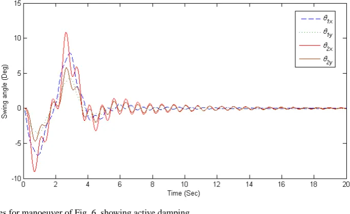
Figure 7.Swing angles for manoeuver of Fig. 6, showing active damping.
Figure 8.Reduction of forces acting on trolley through WBC process.
maximum value of about 10 degrees to less than 2 degrees and they are decaying steadily.
Figure 8 shows the horizontal force components between trolley and cable for the same manoeuvre. The main acceler-ations and deceleracceler-ations occur within 4 s, and after about 6 s the force amplitudes diminish to less than 3 % of the initial peaks. Again WBC is using the forces to combine position control and active vibration damping very effectively.
Figure 9 shows the effect of choosing different values of the impedance parameter Z, as the only control parameter to be tuned, for the single-input manoeuvre of Fig. 5. The reference impedance Z=Zeq is as in Eq. (19), which is the value used to obtain the results presented above. Despite a 12-fold range in impedance values, the responses are good for all cases, showing a stable response, rapid transit and zero steady-state error in the final position. The best choice of Z will depend on the priorities in the desired response.
For example, perhaps a good compromise between minimum overshoot and shortest settling time is when Zx=(0.75)Zeq.
For Zx≥2Zeqthe various responses become almost
indistin-guishable (except around the half-way point). More could have been added for other values of Zx, but they would have
fallen on top of the curves shown. On the other hand for low values of impedance, say Zx<(0.5)Zeq, the trolley has a slow
transient and slow convergence to the target position. The robustness of the control response to variations in Z also indirectly illustrates the robustness of WBC to changes in the system under control, whether these are known or un-known, whether modeled or not. For example, if incorrect values of masses or lengths are assumed in using Eq. (19), or these parameter change during operations, the control system still copes well.
Figure 9.Trolley response to 1 m x direction input with different Z values in the WBC.
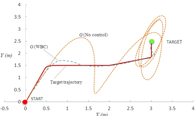
Figure 10.Trajectory tracking, plan view, showing the paths of the mass centre of the load.
immediately the motion requested by the WBC system of Fig. 4. However the system has also been tested with realis-tic trolley dynamics, where the trolley response shows some dynamic delay in achieving the requested motion. The con-trol system still works well, with comparable results to those presented, provided that the steady state trolley error is zero. This robustness to the trolley’s dynamic performance can be explained in part because the measurements used in the WBC control system, including Eqs. (17, 18) come after the trolley (see Fig. 4), using the values of position, xT, yT, and forces,
Fx, Fy, actually achieved and experienced by the trolley.
Finally, in addition to the point-to-point manoeuvres above, input tracking and obstacle avoidance are considered. Figure 10 shows a plan view of a desired input trajectory, and the resulting path of the mass centre of the load, G, both
un-der WBC and with no control. As can be seen, unun-der WBC the tracking is very satisfactory.
5 Conclusions
260 W. O’Connor and H. Habibi: Gantry crane control of a double-pendulum
mechanical impedance term, whose value is not critical, but can be used to fine-tune the transient response as desired.
The results illustrate the power, simplicity, effectiveness and robustness of the control approach. For point to point manoeuvres in the plane, WBC proves very effective. It also performs well in trajectory tracking, often required for obsta-cle avoidance.
Future work will extend the approach to cranes with cable hoisting, to tower cranes in which the trolley moves on a rotating arm, and to jib or luffing cranes in which the arm ro-tates in the vertical plane. Initial results suggest that the same WBC strategy can be extended successfully to all such cases.
Edited by: A. M¨uller
Reviewed by: two anonymous referees
References
Abdel-Rahman, E. M., Nayfeh, A. H., and Masoud, Z. N.: Dynam-ics and Control of Cranes: A Review, J. Vib. Control, 9, 863–908, 2003.
Al-Garni, A. Z., Moustafa, K. A. F, and Javeed Nizami, S. S. A. K.: Optimal control of overhead cranes, Control Eng. Pract., 3, 1277–1284, 1995.
Anti´c, D., Jovanovi´c, Z., Peri´c, S., Nikoli´c, S., Milojkovi´c, M., and Miloˇsevi´c, M.: Anti-Swing Fuzzy Controller Applied in a 3D Crane System, Engineering, Technology & Applied Science Re-search (ETASR), 2, 196–200, 2012.
August, W., Ren, J., Notheis, S., Haase, T., Hein, B., and W¨orn, H.: 3D Pendulum Swinging Control by an Industrial Robot Manipu-lator, 1–7, in: Proceeding of: ISR/ROBOTIK 2010, Proceedings for the joint conference of ISR 2010 (41st Internationel Sympo-sium on Robotics) und ROBOTIK 2010 (6th German Conference on Robotics), 7–9 June 2010, Munich, Germany, 2010. Chen, H., Gao, B., and Zhang, X.: Dynamical Modelling and
Non-linear Control of a 3D Crane, International Conference on Con-trol and Automation (ICCA2005), Budapest, Hungary, 1085– 1090, June 2005.
Cheng-jun, D., Ping, D., Ming-lu, Z., and Yan-fang, Z.: Double In-verted Pendulum System Control Strategy Based On Fuzzy Ge-netic Algorithm, in: Proceedings of the IEEE International Con-ference on Automation and Logistics Shenyang, China, 1318– 1323, August 2009.
Cheng-Yuan, C., Kou-Cheng, H., Kuo-Hung, C., and Guo-En, H.: An Enhanced Adaptive Sliding Mode Fuzzy Control for Posi-tioning and Anti-Swing Control of the Overhead Crane System, IEEE International Conference on Systems, Man, and Cybernet-ics, Taipei, Taiwan, 992–997, October 2006.
Dan, Y. and Li, Z.: The Structure of HSIC System and Its Applica-tion on Arbitrary Switch Control of Double Pendulum, in: Pro-ceedings of the 7th World Congress on Intelligent Control and Automation, Chongqing, China, 2810–2815, June 2008. Forest, C., Frakes, D., and Singhose, W.: Input-Shaped Control of
Gantry Cranes: Simulation and Curriculum Development, The 18th ASME DETC Biennial Conference on Mech. Vib. and Noise, 2001.
Kenison, M. and Singhose, W.: Input Shaper Design for Double-Pendulum Planar Gantry Cranes, in: Proceedings of the I999
EEE International Conference on Control Applications, Kohala Coast-Island of Hawai’i, Hawai’i, USA, 539–544, August 1999. Kim, D. and Singhose, W.: Reduction of Double-Pendulum Bridge Crane Oscillations, The 8th International Conference On Motion And Vibration Control (MOVIC 2006), Atlanta, GA, USA, 300– 305, 2006.
Kim, D. and Singhose, W.: Performance Studies Of Human Op-erators Driving Double-Pendulum Bridge Cranes, Control Eng. Pract., 18, 567–576, 2010.
Maghsoudi, M. J., Mohammed, Z., Pratiwi, A. F., Ahmad, N., and Husain, A. R.: An Experiment for Position and Sway Control of a 3D Gantry Crane, The 4th International Conference on Intelli-gent and Advanced Systems (ICIAS2012), 497–502, 2012. Manning, R., Clement, J., Kim, D., and Singhose, W.:
Dynam-ics and Control of Bridge Cranes Transporting Distributed-Mass Payloads, J. Dyn. Syst.-T. ASME, 132, 014505, doi:10.1115/1.4000657, 2010.
Masoud, Z. N. and Nayfeh, A. H.: Sway Reduction on Container Cranes Using Delayed Feedback Controller, Nonlinear Dynam., 34, 347–358, 2003.
McKeown, D. J.: Wave based Control of Elastic Mechanical Sys-tems, Ph.D. Thesis, Department of Mechanical Engineering, University College Dublin, Ireland, 189 pp., 2009.
Neupert, J., Arnold, E., Schneider, K., and Sawodny, O.: Tracking and anti-sway control for boom cranes, Control Eng. Pract., 18, 31–44, 2010.
O’Connor, W. J.: A Gantry Crane Problem Solved, J. Dyn. Syst.-T ASME, 125, 569–576, 2003.
O’Connor, W. J.: Wave-Based Analysis and Control of Lump-Modeled Flexible Robots, IEEE T. Robot., 23, 342–352, 2007. O’Connor, W. J. and Fumagalli, A.: A Refined Wave-Based Control
Applied to Nonlinear, Bending, and Slewing Flexible Systems, J. Appl. Mech., 76, 041005, doi:10.1115/1.3086434, 2009. O’Connor, W. J. and McKeown, D. J.: A new approach to modal
analysis of uniform chain systems, J. Sound Vib., 311, 623–632, 2008.
O’Connor, W. J., Ramos, F., McKeown, D. J., and Feliu, V.: Wave-based control of non-linear flexible mechanical systems, Nonlin-ear Dynam., 57, 113–123, 2009.
Sawodny, O., Aschemannb, H., and Lahres, S.: An automated gantry crane as a large workspace robot, Control Eng. Pract., 10, 1323–1338, 2002.
Schulze, T. and Chang, T. N.: Zero Vibration Position Control of a Spherical Pendulum for Control Systems Demonstration, Amer-ican Control Conference, Marriott Waterfront, Baltimore, MD, USA, 738–743, July 2010.
Singhose, W. E. and Towel, S. T.: Double-Pendulum Gantry Crane Dynamics and Control, in: Proceedings of the 1998 IEEE In-ternational Conference on Control Applications Trieste, Italy, 1205–1209, September 1998.
Sun, N., Fang, Y., and Zhang, X.: Energy coupling output feed-back control of 4-DOF underactuated cranes with saturated in-puts, Automatica, 49, 1318–1325, 2013.
Tanaka, S. and Kouno, S.: Automatic measurement and control of the attitude of crane lifters; Lifter-attitude measurement and con-trol, Control Eng. Pract., 6, 1099–1107, 1998.
Vaughan, J., Karajgikar, A., and Singhose, W.: A Study of Crane Operator Performance Comparing PD-Control and Input Shap-ing, American Control Conference, San Francisco, CA, USA, 545–550, June 2011.
Yang, J. H. and Yang, K. S.: Adaptive Control for 3-D Overhead Crane Systems, in: Proceedings of the 2006 American Control Conference, Minneapolis, Minnesota, USA, 1832–1837, June 2006.