Sagar S. Kolte1, Shubham R. Bhagat 2, Varun H. Danke3 and Vikram K. Mundhe4 1,2,3,4
Mechanical Engineering, Suman Ramesh Tulsiani Technical Campus, Kamshet, Pune 5
Prof. Nilesh V. Dhumal, Mechanical Engineering, Suman Ramesh Tulsiani Technical Campus, Kamshet, Pune Abstract— In material handling, cranes play a vital role in modern manufacturing industries. An automated overhead chain block reduces the effort required to lift heavy loads. In our project, we aim to manufacture an overhead automated crane for the entire workplace of our company and fabricate a motorized, hydraulic floor crane for handling different types of materials. All the designed structures have been optimized for minimum weight.
I. INTRODUCTION
A 'crane' is a type of machine, generally equipped with a hoist, wire ropes or chains, and sheaves, that can be used both to lift and lower materials and to move them horizontally. It is mainly used for lifting heavy things and transporting them to other places. It uses one or more simple machines to create mechanical advantage and thus move loads beyond the normal capability of a man. Cranes are commonly employed in the transport industry for the loading and unloading of freight, in the construction industry for the movement of materials and in the manufacturing industry for the assembling of heavy equipment. In material handling, the cranes play a vital role in modern manufacturing industries.
Hydraulic cranes are heavy equipment used primarily for lifting. These Hydraulic floor Cranes, provide an efficient low cost alternative to other material handling equipment. These cranes are maneuverable and loading, unloading and shifting of heavy load is very easy. Crane structure consists of chassis, vertical column, inner boom and outer boom, and the hydraulic pump with cylinder assembly.
An overhead crane, commonly called a bridge crane, is a type of crane found in industrial environments. An overhead crane consists of parallel runways with a traveling bridge spanning the gap. A hoist, the lifting component of a crane, travels along the bridge.
„Computer aided engineering‟ is the use of computer software to stimulate performance in order to improve product designs or assist in the resolution of engineering problems for a wide range of industries. This includes simulation, validation and optimization of products, processes and manufacturing tools. The study of behavior of components in real time conditions in CAE is achieved through Finite Element Analysis (FEA). FEA is a computing technique that is used to obtain approximate solutions of Boundary Value Problems. It uses a numerical method called Finite element Method (FEM). FEA involves a computer model of a design that is loaded and analyzed for specific results.
II. DESIGN OF COMPONENTS
For our crane structure, we have designed the following components:
1. Beam 2. Column 3. Channel 4. Wheel
2.1Design using theoretical process (analytical method):
2.1.1 Design of beam:
The material selected for the beam is Fe 410. This material is used in 90% manufacturing works as it is cheap and readily available.
The material properties are:
Ultimate tensile strength (σu) = 410MPa
Considering FOS = 2
Yield tensile strength (σy) = 220MPa
Young‟s modulus (E) = 210GPa Allowable bending stress (σb) = 110MPa
Available Data:
Total weight on beam (W) = 3500kg = 34335 N≈ 35000N Total length of beam (L) = 12m = 12000mm
For our application, we have selected an optimized cross-section. The optimization has been done for minimizing weight of the structure which will in turn reduce the cost of material required for manufacturing the structure. For optimization, we followed the iterative approach and kept changing the dimensional parameters of the cross-section. After 11 iterations, we arrived at the conclusion that ISMB 200 which is a standard structure with a plate of 400 x 20 mm welded to it longitudinally yielded the best result in terms of deflection and stress.
For ISMB 200 (with plate of dimension 400mmx 20mm)
Figure 1. Cross-section of beam Ixx = 4.24 x 10^8 mm4
Deflection of beam (δ) = WL³/48*E*I (Standard deflection of beam formula)
= 14.139 mm
1.1.1 Design of column By Euler‟s formula,
For, 1 end fixed and 1 end free column, Pc= π²E*Ic/4*Lc²
Where, Pc = Buckling load,
E = 205 GPa,
L c= Length of column.
And Ic = Moment of inertia of considered column section.
Figure 2.Cross-section of column. Pc = π² x 205 x 10^3 x 7.88 x 10^6/ (4 x 5400²)
= 136688 N Considering FOS = 2
Safe load = Pc /FOS = 136688/2 = 68340 N
≈ 6.9 tonne
The total weight of the structure which consists of the beam and crane system is 4.7 tonne. Considering safety to be paramount and taking into account the service factor of the structure, we select a higher FOS of 2.7 and calculate a new safe load.
Safe load = Pc/FOS = 136688/ 2.7 = 5 tonne.
For this column , stress is found by Stress = Force/ Area = 15.78 MPa Thus, the selected design is safe.
2.1.2 Design of channel
The material selected for the beam is Fe410. This material is used in 90% manufacturing works as it is cheap and readily available.
Available Data:
Total weight on beam (W) = 5000kg = 49050N Total length of beam (L) = 5m = 5000mm
Similarly, using optimization, the selected section is ISMB 200 which is a standard cross-section.
For ISMB 200x100 Ixx = 223.54x106 mm4
Deflection of channel (δ) = (W×L³)/ (48×E×I)
= (49050×5000³)/ (48×2 x 10³×223.54x 106 ) = 2.857 mm
2.1.3 Design of wheel:
Design of wheel is done by considering the wheel supporting the beam on the channel as a shaft. F = force on wheel 3000+1200 × 9.81 = 41202 N
L = length of wheel = 115 mm D = diameter of wheel = 110 mm d = internal diameter of wheel = 55 mm p = permissible bearing pressure on wheel =?
Allowable shear stress for alloy steel is 10 to 100
Bending stress for wheel:
Allowable bending stress for alloy steel is 140 to 190N/mm2hence design is safe.
2.2 Design using Finite Element Method: 2.2.1 Design of beam:
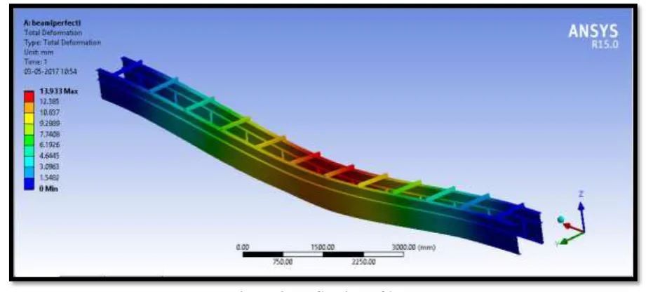
The analysis was done using ANSYS R15.0. The deformation image is shown below: Deflection is 13.933mm
Figure 3. Deflection of beam
Areas of heavy stress concentrations have been strengthened by adding suitable ribs.
2.2.2 Design of column:
Stress of column image: Stress is 16.195 MPa
2.2.3 Design of channel:
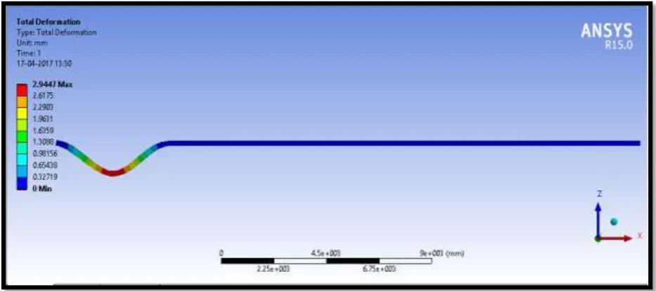
Deformation of channel: Deflection is 2.9447 mm
Figure 5. Deformation in channel
2.2.4 Design of wheel:
Stress in wheel image : Max stress = 4.7402 MPa
Figure 6. Stress in wheel
III. COMPARATIVE RESULT TABLE
The results are tabulated as follows:
SR.NO. DESCRIPTION ANALYTICAL
RESULT (A)
FEM RESULT (B)
ERROR |(A) – (B)|
IV. CONCLUSION
Thus, we can conclude that both the methods yield similar results with a very negligible error. Hence, any procedure can be used for designing components.
REFERENCES
[1] Ibrahim O Abdulmalik ,Michael C Amonye, Mahdi Makoyo ,Ahmed A Kano, Abdulfatai O Ambali and Akonyi N Sule. “Design and manufacture of a hydraulic workshop crane”, ISSN 2319-5991, Vol.3, No.-3, 2014.
[2] A. Balaji, H. JahirHussain, M.R. FaheenAshkar, Department of Mechatronics Engineering, Kongu Engineering College, Erode, India. “Design optimization of Floor Cranes”.
[3] Okolie Paul Chukwulozie , ObikaEchezonaNnaemeka, AzakaOnyemazuwa Andrew and Sinebe Jude Ebieladoh, Department of Mechanical Engineering, NnamdiAzikiwe University, P.M.B. 5025 Awka, Anambra State, Nigeria [4] Dhaval H Kanjariya, M.E. Student ,A.D.Patel Institute of Technology, New V.V.Nagar, Gujarat. “A review on design
and analysis of hoisting machinery in EOT crane”, IJSRD , Vol. 3, Issue 02, 2015| ISSN 2321-0613 .
[5] Venkatesh A. ,Vignesh S. , Iyappan S. , Vignesh Kumar P. , Tamilvanan G. andVijayaSarathy R. BE final year project, Department of Civil Engineering, P.R.Engineering College, Vallan, Thanjavur. “Design of an overhead plate gantry girder”, IJDR, Vol.6, Issue 05, pp. 7821-7823, May 2016.
[6] Sam Hutcheson, BioResource and Agricultural Engineering BioResource and Agricultural Engineering Department California Polytechnic State University, San Luis, Obispo. “A report on Design and construction of a portable gantry crane”.
[7] Ms. Kavita R. Kapadni, Prof. S. G. GanigerPG Student, Department of mechanical, JSPM‟S ICOER, Wagholi, Pune, Maharashtra, India 2 Assistant Professor, Department of mechanical, JSPM‟S ICOER, Wagholi, Pune, Maharashtra, India. “A Review Paper on Design and Structural Analysis of Simply Supported Gantry Crane Beam for Eccentric Loading”,International Research Journal of Engineering and Technology (IRJET) Volume: 02 Issue: 08 | Nov-2015 [8] Patel Paresh, NiravKamdar PG Student, Assistant Professor, KIRC Kalol, India. Design and Analysis of Major