Abstract—Multi-fingered robot hand is the one which can be employed in power grasping as well as precision grasping. Mechanical hands find use in remote manipulations in space, nuclear and undersea exploration and prosthetics. Development of such dexterous hand is a challenging one. On the attempt of developing a three fingered robot hand, firstly, the mechanical structure of the hand is done. Forward kinematics has then been done on the designed hand using D-H method. The graphical approach has been used in this paper for inverse kinematics in order to find joint angles for the different configurations. The results obtained from the inverse kinematics are then compared with forward kinematics results in order to validate the developed model.
Index Terms—Denavit-Hartenberg (D-H), multi-fingered hand, inverse kinematics, power grasping, precision grasping.
I. INTRODUCTION
Gripper is used not only for prehension and also for manipulation of objects in assembly operation. It is able to perform pressing, fitting and joining operations. Some are involved in house hold applications that help old and disabled people. In the recent years, miniaturized grippers have been developed in order to handle delicate components in micro technology. Having the above significant reasons, the research is now focused towards the development of multi-fingered robot hand, dexterous hand and anthropomorphic hand. The multi-fingered hand will be more suitable for tele-operated surgery for handling delicate organs, poultry industries, bottle industries etc. Dexterous hand is one with three or more jointed fingers and could be able to perform sophisticated programmed or remote controlled operations. Anthropomorphic hand mimics the characteristics of human hand. Anthropomorphism is not in itself a necessary or sufficient condition for achieving dexterity of a robot hand [1]. Grippers are sometimes tailored to the shape and size of the objects. Multi-fingered robot hands were mostly named after their institution or the place where they were developed. Okada hand, Salisbury hand, UTAH/MIT hand, Belgrade / USC hand, UB Hand, DIST hand, DLR hand, Gold finger hand, Robonaut hand, Black fingers hand, Barrette hand, TUAT/Karlsruhe hand, BUAA hand, Gifu hand, Hiroshima hand, Shadow hand, Cybernetic hand are robotic hands developed all over the world [2]. Some of the above hands have five fingers and some with four fingers. Five fingered hands have been tried for emulating human hands. But it is found from the
Manuscript received July 18, 2012; revised February 5, 2013.
The authors are with the School of Mechanical Engineering, Linton University College, Negeri Sembilan, West Malaysia (e-mail: [email protected], [email protected]).
literature that atleast four frictionless points are required to immobilize an object in 2D space. Lakshminarayana [3] showed that seven frictionless contact points are needed to immobilize an object in 3D. The closure properties depend on the first order kinematic analysis and its grasp depends on the locations of the contact points and the contact normals, but not on the shape of the object and the contacting effectors. Having this in mind, three fingered robot hand has been attempted. A very basic problem in the study of mechanical manipulation of the hand is called forward kinematics. This is the static geometrical problem of computing the position and orientation of the hand. Specifically, given a set of joint angles, the forward kinematic problem is to compute the position and orientation of the tip of the finger relative to the base of the finger. Computing joint angles of the finger for the given position and orientation of the fingertip is called inverse kinematics. Kinematics and dynamic analysis of the manipulators have been done by many authors [4], [5], [6], [7], [8]. Mina et al. [9], Bundhoo and Park [10], Ramasamy and Arshad [11] have derived kinematic and dynamic equations for their multifingered robot hand. Corrales et al [12] discussed the forward and inverse kinematics of an under actuated hand model. This paper discusses the forward kinematics and inverse kinematics of a three fingered robot hand which is going to be developed.
II. SOLID MODEL
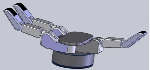
Fig. 1 illustrates the solid model of the proposed robot hand. It has three fingers; two fingers are in series and other one opposes them. There are three phalanges (links) in each finger. The proximal link has fixed joint and is attached to the base. Median and distal links have one degree of freedom (dof) rotational joints. In addition, palm is also introduced if power grasping is to be done
.
The material selected for the hand prototype is aluminum.Fig. 1. Solid model of the proposed hand Elango Natarajan and Litu Dhar
Fig. 2. Model of one finger
Fig. 2 shows the model of a finger which has four frames attached to its joints. The base frame is referring the fixed joint, which is indicated as X0, Y0, Z0. X1, Y1, Z1 andX2, Y2, Z2 are representing joint 2 and joint 3 respectively, whereas X3,
Y3, Z3 is representing the fingertip position.
III. FORWARD KINEMATICS
Forward kinematic is used to determine the position and orientation of the fingertip relative to the robot base coordinate system. The derivation of forward kinematic equation is done as follows
.
Fig. 3. Denavit hartenberg (DH) frame [13]
where,
= Joint angle of the finger = joint distance of the finger
= link length of the each joint
= link twist angle
The following Homogeneous transform equations are used to determine the transform between base frame X0, Y0,
Z0 to the finger tip frame X3, Y3, Z3. Equation (1) is the generalized equation representing the transformation between the frames i-1 and i.
− 0
− −
0 0 0 1
(1)
− 0 0
0 0
0 0 1 0
0 0 0 1
. (2)
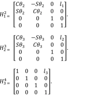
− 0
0 0
0 0 1 0
0 0 0 1
. (3)
− 0
0 0
0 0 1 0
0 0 0 1
. (4)
1 0 0
0 1 0 0
0 0 1 0
0 0 0 1
. (5)
where, S and C represent Sine and Cosine.
It is known that, = [ ] and hence, the
forward kinematic equation for the fingers of the proposed robot hand is obtained as
( + + ) – ( + + ) 0 + ( + ) + ( + + )
( + + ) ( + + ) 0 + ( + ) + ( + + )
0 0 1 0
0 0 0 1
(6)
IV. INVERSE Kinematics
Inverse kinematics has multiple solutions for a specific position and orientation of the finger tip. The existence or nonexistence of a kinematic solution defines the workspace of a given finger. The lack of a solution means that the finger cannot attain the desired position and orientation because it lies outside of the finger workspace.
Let the given orientation be
=
( + + ) − ( + + ) 0
( + + ) ( + + ) 0
0 0 1 0
0 0 0 1
(7)
From the derived forward kinematic homogenous matrices as given below,
=
( + + ) − ( + + ) 0 + ( + )
( + + ) ( + + ) 0 + ( + )
0 0 1 0
0 0 0 1
(8)
x = + ( + ) . (9)
y = + ( + ) . (10)
Squaring both of sides of the equations x and y and adding them,
+ = [ + ( + )] + [ +
( + )]
= l12( + ) + {[ ( + )] + [ ( + )] } +
2 [ + - + (11)
+ = + + 2 ..
= .
Sθ2 = ± √1 − θ22
= ( ) .
Having found , now equations (9) and (10) can be
solved for
Writing equations (9) and (10) in the following form
x = – . (12)
y = + . (13)
where, k1 = l1 + l2 and k2 = l2
assuming
r = + and = ( , )
= and =
Substituting the above in equations (12) and (13)
⁄ = − = ( + )
= + = ( + )
Using the two argument arctangent,
( + ) = atan ( , ⁄ ) = atan ( , )
= ( , ) − ( , )
can be solved by using the equation ( + + )
and ( + + )
Let
+ + = , =
= , − −
where, = ( + + ) and = ( + + )
Hence joint angles are
= ( , ) − ( , ) (14)
= ( , ) (15)
= , − − (16)
The solution for inverse kinematic equations can be obtained in either iteration solution technique or graphical technique. The later has been used for finding the joint angles for different configuration of the finger and for different object shapes.
V. RESULT ANALYSIS AND DISCUSSION
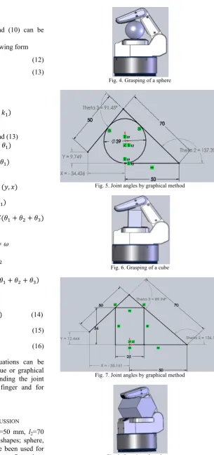
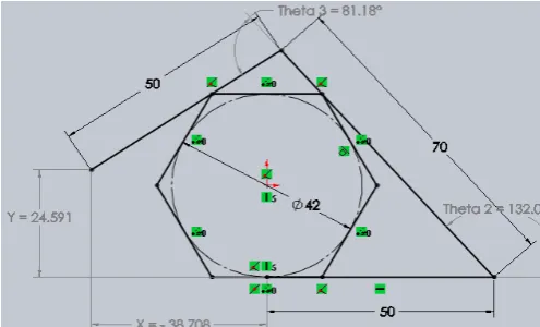
The link lengths are considered to be l1=50 mm, l2=70 mm and l3=50 mm. Three different object shapes; sphere, cube and polygon and of various sizes have been used for the analysis. Fig. 4-Fig. 9 show some configurations
considered for the analysis. The joint angles are measured graphically for various configurations and then compared with the forward kinematics results in order to validate the developed kinematic model. Table I, Table II and TableIII show the comparison of inverse kinematic results with forward kinematic results for a few configurations.
Fig. 4. Grasping of a sphere
Fig. 5. Joint angles by graphical method
Fig. 6. Grasping of a cube
Fig. 7. Joint angles by graphical method
Fig. 9. Joint angles by graphical method
It is found from the analysis that the results obtained from graphical method well match with forward kinematic results. It is also observed from the analysis that the hand can grasp spheres of 40 mm to 164 mm, but it could not grasp 165 mm object because joint 3 will be perpendicular in that case. The cube of (25 × 36) mm to (25 × 59) mm can be grasped and it could not grasp (25 × 60) mm object because height of the object is more than the finger height. Minimum 38 mm to maximum 62 mm Polygon shape object can be grasped. It could not grasp more than 62 mm object because height of the object is more than the finger height.
TABLEI:COMPARISON OF JOINT ANGLES
Sphere Joint angles measured by graphical method (x,y) tip position measured by Forward Kinematics (equation 8)
40 mm = 00, = 136.400, = 900 x = -35.172 mm, y = 12.06 mm
= 00, = 136.400, = 900 x = -35.175 mm, y = 12.07 mm 50 mm = 00, = 126.870, = 77.320
x = -37.610 mm, y = 35.512 mm
= 00, = 126.870, = 77.320 x = -37.610 mm, y = 35.512 mm
70 mm = 00, = 110.020, = 59.490 x = -23.123 mm, y = 74.879 mm
= 00, = 110.020, = 59.490 x = -23.12 mm, y = 74.873 mm 165 mm = 00, = 62.440, = 27.250
x = 82.661 mm, y = 112.054 mm
= 00, = 62.440, = 27.250 x = 82.661 mm, y = 116.059 mm
TABLEII:COMPARISON OF JOINT ANGLES
Cube (L × H) in mm Joint angles measured by graphical method (x,y) tip position measured by Forward Kinematics 25 × 35 = 00, = 136.970, = 91.440
x = -34.362 mm, y = 10.365 mm
= 00, = 136.970, = 91.440 x = -34.36 mm, y = 10.37 mm
25 × 40 = 00, = 133.150, = 83.970
x = -37.745 mm, y = 20.894 mm
= 00, = 133.150, = 83.970 x = -37.741 mm, y = 20.895 mm 25 ×52 = 00, = 125.800, = 66.700
x = -39.760 mm, y = 45.960 mm
= 00, = 125.800, = 66.700 x = -39.761 mm, y = 45.953 mm
25 × 59 = 00, = 122.440, = 57.740
x = -37.549 mm, y = 58.923 mm
= 00, = 122.440, = 57.740 x = -37.549 mm, y = 58.919 mm
TABLEIII:COMPARISON OF JOINT ANGLES
Polygon Joint angles measured by graphical method (x,y) tip position measured by Forward Kinematics 37 mm = 00, = 136.740, = 91.770
x = -34.102 mm, y = 10.517 mm
= 00, = 136.740, = 91.770 x = -34.101 mm, y = 10.518 mm
38 mm = 00, = 135.770, = 89.280 x = -35.484 mm, y = 13.449 mm
= 00, = 135.770, = 89.280 x = -35.482 mm, y = 13.441 mm 60 mm = 00, = 118.580, = 63.920
x = -33.435 mm, y = 59.298 mm
= 00, = 118.580, = 63.920 x = -33.438 mm, y = 59.29 mm 62 mm = 00, = 117.370, = 62.890
x = -32.185 mm, y = 61.935 mm
= 00, = 117.370, = 62.890 x = -32.18 mm, y = 61.937 mm
VI. CONCLUSION
Forward kinematics has been developed for the designed three fingered robot hand using D-H method. The graphical approach has been used for inverse kinematics in order to find joint angles for the different configurations. The results obtained from the inverse kinematics are then compared with forward kinematics results. It is obvious that the
REFERENCES
[1] G. J. Monkman, S. Hesse, R. Steinmann, and H. Schunk, Robot Grippers, Wiley-VCH Verlag GmbH & Co, 2007.
[2] N. Elango, “Investigations on the Suitability of Different Soft Materials and Configurations for Robot Fingers,” Ph.D. dissertation, Department of Mechanical Engineering, Anna University, Chennai, India, 2010.
[3] K. Lakshminarayana, “Mechanics of Form Closure,” ASME 78-DET-32, 1978.
[4] R. G. K. M. Aarts and J. B. Jonker, “Manipulators Using Adaptive Modal Integration Dynamic Simulation Of Planar Flexible Link,” International Journal of Multibody System Dynamics, vol.7, no.1, pp 31-50, 2002.
[5] K. Cleary and T. Brooks, “Kinematic Analysis of a novel 6-DOF Parallel Manipulator,” in Proc. IEEE International Conference on Robotic and Automation, pp.708-713, 1993.
[6] P. K. Artemiadis and K. J. Kyriakopoulos, “EMG-based Position and Force Control of a Robot Arm: Application to Teleoperation and Orthosis,” in Proc. IEEE/ASME International Conference on Advanced Intelligent Mechatronics, pp.1-6, 2007.
[7] Y. Yavin, “Control of a Three-Link Manipulator with a Constraint on the Velocity of its End-Effector,” in Proc. Computers and Mathematics with Applications, vol.40, pp. 1263-1273, 2000. [8] R. Ben-Horen, M. Shoham, and S. Djerassi, “Kinematic, Dynamic
and construction of a Planarly Actuated Parallel Robot,” International Journal of Robotics and Computer Integrated Manufacturing, vol.14, issue 2, pp. 163-172, 1996.
[9] M. Terauchi, K. Zenba, and A. Shimada, “The cooperative control system of the robot finger using Shape Memory Alloys and Electrical
Motors,” in Proc. IEEE International Workshop on Advanced Motion Control, pp.733-737, 2008.
[10] V. Bundhoo and E. J. Park, “Design of an Artificial Muscle Actuated Finger towards Biomimetic Prosthetic Hands,” in Proc. 12th
International Conference on Advanced Robotics, Seatle, pp. 368-375, 2005.
[11] S. Ramasamy and M. R. Arshad, “Robotic Hand Simulation with Kinematics and Dynamic Analysis,” in Proc. TENCON, vol.3, pp.178-183, 2000.
[12] J. A. Corrales, C. A. Jara, and F. Torres, “Modelling and Simulation of a Multi-fingered Robotic Hand for Grasping Tasks,” in Proc. 11th International Conference on Control, Automation, Robotics and Vision, Singapore, pp.1577-1582, 2010.
[13] J. Craig, Introduction to Robotics: Mechanics and Control, John Willey and Sons.
Elango Natarajan was awarded Ph.D. from Anna University, Chennai in 2010 in the specialization of Mechanical Engineering. He has been teaching undergraduate and post graduate Engineering courses from 1999 onwards. His specialization is Soft Robot Hand and currently working on different projects on soft robotics and soft manipulations. He is a professional member of IEEE, IET and some national professional bodies.