Abstract—Multi-function construction platforms (MCPs) as an "old construction technology, new application" of the building facade construction equipment, its efforts to reduce labor intensity, improve labor productivity, ensure construction safety, shorten the duration of construction and other aspects of the effect are significant. In this study, the functional analysis of the multi-function construction platforms is carried out in the construction of the assembly building. Based on the general finite element software ANSYS, the static calculation and dynamic characteristics analysis of the MCPs structure are analyzed, the simplified finite element model is constructed, and the selection of the unit, the processing and solution of boundary are under discussion and research. The maximum deformation value, the maximum stress value and the structural dynamic characteristic model are obtained. The dangerous parts of the platform structure are analyzed, too. Multiple types of MCPs under engineering construction conditions are calculated, so as to put forward the rationalization suggestions for engineering application of the MCPs.
Index Terms—Prefabricated concrete (PC), construction, multi-function construction platforms (MCPs), mechanics analysis, ANSYS, finite element method.
I. INTRODUCTION
Since the 21st century, especially in the last five years, with the sustained and rapid development of Chinese economy, China's urbanization and urban modernization process accelerated, energy-saving and environmental protection requirements increased, labor costs continued to grow. In China, the research and application of precast concrete assembly construction technology and Building gradually warming up, and promoting the building assembly is the general trend [1].The State Council issued the "Guidance on the development of fabricated buildings" and put forward eight tasks to implement the five development concept of fabricated buildings by the Chinese government, not only the strongest voice to vigorously develop the assembly of the building , but also the solemn commitment to the world[2]. From a global perspective, the three major trends for the develop of the construction industry include greenization, informatization and industrialization. The assembly structure is in line with this trend, and it is also an important part of the
Manuscript received July 5, 2017; revised January 1, 2018.
F. Rong Xu is with the Department of Building Engineering of Tongji University in China, China (e-mail: [email protected]).
S. Meihua Wang is with Shanghai Construction Group, Shanghai, China (e-mail: [email protected]).
T. Rongshuai Li is with the Shanghai Construction Group, Doctor of Technical Science, Engineer, China (e-mail: [email protected]).
Paris Declaration on Climate Change and the China-US Joint Statement ([3]).
Zhou, J. H. [3], who is Academician of Chinese Academy of Engineering (CAE), pointed out that to develop assembly-style buildings, building standardization is the premise. The structural components industrialization and new building materials is the material basis, on-site assembly and construction mechanization is a necessary mean. Shen, Z.Y., (Academician of CAE) [3] proposed to achieve a new type of construction industry needs research and development, including structural system, enclosure system, building parts system and other integrated decorative technology. Building assembly is now widely carried out in China, but still faces many problems, mainly including as the following: (1) The design and construction are still separated because the investors, designers, manufacturers of the components and the construction side are independent to each other, it is not conducive to the promotion of assembly building. (2)Assembly technology research is immature. The structural design of prefabricated wall has been preliminary solved, in addition, the thermal performance of exterior shear wall joints, waterproof performance, the joints shrinkage cracks for the new and old concrete and other issues are still not solved well. (3)The existing standards are imperfect. Design and construction concepts are based on the concept of cast-in-place, and the concept of assembly is not formed.
At present, in the construction of the facade of the assembled building, the traditional steel scaffolding or electric basket as the main construction equipment are basically used. During the erection of steel scaffolding, the working procedures are various and
the operations are complex, which leads to the waste of labors, serious resource consumption and low production efficiency. Electric basket is high altitude equipment, the use of its process also has many issues, such as single function, unsafe construction, poor stability, etc. Therefore, it is necessary to develop a kind of fast, safe and efficient construction equipment, which is suitable for prefabricated construction in order to meet the rapid development of assembly buildings. Multi-function construction platforms (MCPs), as a kind of portable and efficient facade construction equipment, can be quickly assembled to form a construction platform for the construction of the building facade. It can be used as a structural external protection system, became a strong guarantee for construction [4]-[9]. In order to ensure the safe operation of MCPs, it is very significant to study the mechanical characteristics of MCPs before application.
In this paper, taking the construction loads, operators and
Application and Mechanics Analysis of Multi-function
Construction Platforms in Prefabricated-Concrete
Construction
operating load, wind loads and other environmental loads into consideration, combined with the finite element theory, the three-dimensional finite element model of MCPs is established by using ANSYS finite element software. On this basis, the static and dynamic characteristics of MCPs model are analyzed respectively, which are used to evaluate the safety and reliability of MCPs. By static calculation of various types of MCPs under differences conditions of engineering application, the maximum deformation and the maximum stress value, and analysis of the dangerous part of MCPs structure are obtained. Furthermore, the natural frequency and mode of MCPs structure are calculated by calculating the dynamic characteristics of the model. And finally put forward reasonable suggestions for the application of MCPs in engineering.
II. FUNCTION ANALYSIS OF MULTI-FUNCTION
CONSTRUCTION PLATFORM
Multi-functional construction platforms (MCPs), according to the characteristics of the construction platforms and the functional requirements of the assembly building construction, can be divided into several types: such as a tool-based protection system, as for hoisting of the prefabricated concrete (PC) components, as auxiliary external facade construction, etc.
A. As a Tool-Based Protection System
MCPs climb to the operating layer of the structure. Its work platform and railings are used as a part of the protection system of the facade construction, forming a movable protection system for building external facade construction. Application of MCPs in prefabricated construction can remove the movable enclosures with the fixed bolt, the ordinary steel pipe scaffold and the tools combination of falsework system and, etc. Taking the assembly structure of PC external wall as example, conventional construction needs to set the external safety protection that required steel scaffolding, climbing scaffolding or special enclosure system, the use of conventional enclosure system will cause a lot of waste of materials and labors with bad economy.
B. As for Hoisting of the Prefabricated Concrete (PC) Components
PC components’ installation is often accompanied by its positioning, measuring, fixing and correcting, by steels’ banding, templates’ lapping, prefabricated wall joints processing and other details operations. According to China's domestic projects research, the author found that the above-mentioned multi-channel detail process was a special technology for the construction of the assembly building. Because the current facade erection did not develop a unique construction equipment, the construction process suffering a lot of high-altitude operations and non-standard construction phenomenon.
C.As Auxiliary External Facade Construction
The external facade construction is one of the core functions of MCPs. Prefabricated building facade construction includes the following contents: concrete surface
wall leveling, Playing the priming-coat surface plaster, External wall insulation, facade multi-channel paint whitewash, external-wall facing brick, facade by the dry hanging stone, installation of the outside window, facade rainwater pipe layout and other construction technologies. The process has the characteristics of wide range, involving the numerous processes. Compared to the erection of scaffolding or hanging-basket equipment, MCPs has obvious advantages. The platform can be docked at any desired position, which is comfortable for operator’s operation, reducing labor intensity, improving work efficiency. Different from the hanging-basket equipment, MCPs can be installed from the bottom of the structure in the construction. With the progress of the construction schedule, it can be lifted or lowered to do the decoration operations and does not interfere with other processes. Therefore, the construction period will be guaranteed.
III. MCPS STRUCTURE AND NUMERICAL MODEL
A. Introduction of Multifunctional Construction Platforms (MCPs)
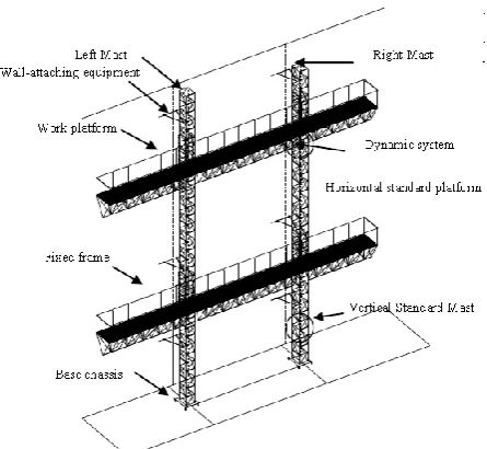
Multi-function construction platforms (MCPs) are divided into single-mast form and double-mast form, and the whole equipment is mainly composed of mast frame device, working platform device and power system. The mast frame device includes vertical standard section, climbing guide rail, base frame, operating platform fixed frame, wall-attaching equipment; The working platform device was comprised by horizontal standard section, railing and connecting pieces; Power system is to control the lifting or lowering of the working platform, the base according to the requirements of the building can be set stationary and mobile. Between the mast device and the building, the upper and lower groups of attachment devices are arranged at a certain distance. According to functional requirements, MCPs can be set as single-stage or multi-level. The Multi-level of MCPs structure diagram is showed in Fig. 1.
B. Numerical Model of Multi-functional Construction Platforms (MCPs)
1) Model simplification
In order to ensure the accuracy of calculation, reduce the scale of calculation and make the model to reflect the real mechanical properties of MCPs, in the modeling process, the actual structure of MCPs needs to be simplified. This article mainly focuses on the mechanical properties of MCPs structure under different loads conditions. Therefore, the influence of local stress concentration on the overall structure is neglected. According to their structural characteristics and working conditions, we can make the following simplifications.
1) Vertical standard section, between the wall device and the prefabricated wall and so on are bolted. This paper assumed that the bolts strength are sufficient, no damage, so simplified can be considered as the rigid connection ;
holes, etc.
3) Regardless of the change in the properties of the weld material, it is considered that the material properties of the weld are the same as those of the adjacent structure.
Fig.1. A design diagram of multi - functional construction platforms(MCPs).
2) Options of the finite element type
MCPs belong to three-dimensional (3D) space truss structure. In ANSYS, the 3D beam elements include BEAM4, BEAM188, BEAM189.Among them, BEAM4 is a single-axis force unit, that can be used to withstand tension, pressure, bending moment and torque, used to simulate the 3D general beam. The units of BEAM188 and BEAM189 not only maintain the main features of the beam element with the characteristics of a one-dimensional component that approximates to the three-dimensional solid structure, but also enhance its cross-section definition function and improve the visualization of the other two dimensions of the beam member. In addition, the element takes the effects of shear deformation into account. In the element interpolation function, the deflection and cross section rotation are individually interpolated. Furthermore, BEAM188 is a linear beam element with a stronger nonlinear analysis function [10]. So the beam components of MCPs all select element of BEAM188 unit to simulate. In the mast device and work platform device, the web member of the truss structure are consisted of reinforced, and welded with the main frame, can transmit axial force and bending moment, so we can choose PIPE16. Since the pedal of horizontal operating platform device is a steel wire mesh, which has no influence on the overall force of MCPs. Therefore, the steel wire mesh can be converted into loads acting on the construction platform. The section type of element and the real constant are shown in Table I.
TABLEI: SECTION TYPE OF ELEMENT AND REAL CONSTANT
component Unit type real constant and ID
Mast device
BEAM188 □40×40×3;ID=1
BEAM188 ∟40×40×3;ID=2
PIPE16 O Ø16×8;ID=3 Work platform BEAM188 □50×50×4;ID=4
BEAM188 □30×80×2;ID=5
PIPE16 O Ø16×8;ID=6
Wall-attaching equipment BEAM188 □40×40×3;ID=7
Fixed frame PIPE16 O Ø40×10;ID=8
C. Loads and Boundary Conditions
According to the maximum allowable loads of MCPs to calculate, the construction platform factory takes the construction load based on the construction platform design requirements: Q1=15kN,With uniform loads to consider. Criterions [11] provided that the ground above the six winds do not carry out the platform operations, installation and demolition, so Wk=0.11KN/m2. The quality of each person is 80kg and the quality of each carrying device is 40kg, assuming that the manual operation force is 20kg. Take the operator loads of Q2 = 1.4kN, to consider as the concentration of load. The specification [11] sets that Single guide platform are no more than 2 peoples, multi-guide platform is for 4 peoples.
According to the provisions of the codes [11]-[13], MCPs loads can be divided into: ①rated uniform loads;②125% rated uniform loads (to withstand dynamic test loads);③The telescopic beam of the working platform extends 1.5m;④ Lateral loads (including wind loads and man-made lateral loads);⑤Concentrated forces bias.
This paper mainly analyzes the following four kinds of load conditions:
Case1:①④⑤; Case2:①③④⑤; Case 3:②④⑤; Case 4:②③④⑤.
The connection between the wall-attaching equipments and the wall generally use embedded welding or reserved hole through the wall bolts and so on, so the connection-nodes can pass the bending moment and shear force, therefore the point can be treated as a fixed point.
D.Establishment of Finite Element Model
Taking the MC-36/15 double-mast / single-mast MCPs as an example, the finite element analysis are established. The endpoints of the components are defined as the key point, and the finite element model of MCPs are established by dividing their units. There are a total of 1838 units and 1014 nodes, as shown in Fig. 2. In the modeling, loading and solving process, only the elastic situation is considered, regardless of the impact of materials plasticity. Q235 steel is used in the steel frame and pedal of MCPs.
IV. STRUCTURAL SOLUTION AND ANALYSIS
A. Analysis of Static Characteristics
nephogram is MPa, and the displacement unit of the deformation nephogram is mm. In order to make the model truly reflect the actual structure of MCPs, the self-weight of MCPs are applied to each unit in the form of inertial forces, and the gravitational acceleration is in the opposite direction of the Z-axis of MCPs.
According to the functional requirements of the application of the assembled building construction, MCPs will be used in four types: double mast, single mast, single layer and multiple layers. In this paper, the four combinations of application types are respectively calculated under the four kinds of working conditions in the static stage, in order to check the strength and stiffness, and provide suggestions for construction application. Table II shows the results of stress and deformation in four conditions.
TABLEII:THE RESULTS OF STRESS AND DEFORMATION IN FOUR
CONDITIONS
Single-mast&Single-layer Single-mast&multi-layers 1.2,1.2 2.4,0 1.2,1.2 2.4,0
Case 1 1.2,1.2 2.4,0 1.2,1.2 2.4,0
70.8 101 76.3 128
Case 2 4.948 29.669 7.86 28.759
162 158 167 161
Case 3 28.216 59.478 32.35 58.772
81.8 160 80.4 159
Case 4 5.865 32.137 6.605 32.137
202 201.8 202.3 201.2
Note: the calculation results under different cases: the first line is stress, the second line is deformation, where 1.2 indicates that the operator applies the concentrated load, and the unit is KN.
Reference codes [13] specifies the mechanical properties of the structural steel, the proportional limit is 200MPa and the yield point is 235MPa. When the working platform is under loads, the maximum deflection value of the main beam in the bottom of platform shall be less than 1/500 of the length of platform, and the secondary beam shall be no more than 1/250 of the length of the platform. So the maximum deflection allowed by the platform is 30mm or 60mm.
As shown in Table II, under the four working conditions of
MCPs in addition to the individual
(Double-mast&multi-layers in case 4), the four types of MCPs all meet the required strength and deflection requirements. According to the assumptions of load cases, the working cases from one to four are all fully loaded. The above data shows that the strength and stiffness have obvious differences in the different types of MCPs under different bias loads.
As shown in Table II, in the same type of MCPs under the same load bias effect, the difference of maximum stress value has very small in the case1 and case3, and those values are also very close in the case2 andcase4.The case1 and the case3
under the same load bias, the maximum displacement of MCPs is 4.039mm to 10mm, which is generally small. Yet, The maximum displacement of the case2 and the case4 reaches 58.947mm,which is generally large and occurs at the end of the telescopic beam cantilever of working platform.
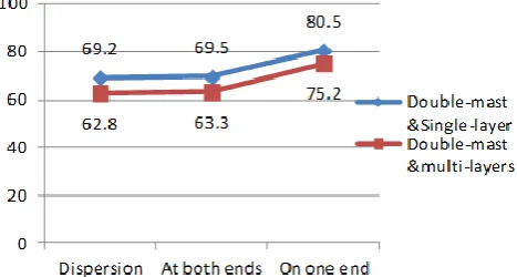
Combined with Fig. 3, under the case1 and case2 within the same load bias effect, the maximum stress value of MCPs is from 59.2MPa to 162MPa, and the change is significant. Fig. 4 shows that under four concentrated loads, the maximum stress occurs on the cantilever solid end of the telescopic beam. Therefore, the reason for stress value and displacement value are larger in the case2 and case4, due to the platform telescopic beam extension 1.5m, and the concentrated load produces larger bias. As shown in Fig. 4, the webs of the triangular trusses shows that the webs are presented as different colors monochromatic tie rods, which indicates that the webs of the space truss units have the axial force distribution.
Fig. 5. Contrast curve of the maximum stress for double-mast& multi-layers and Double-mast& Single-layer.
161
162
171
59.2
60.5
69.1
0
50
100
150
200
Dispersion At both ends On one end
Fig. 3. Contrast curve of the maximum stress for Double-mast&multi-layers under case2 and case4.
Fig. 6. Contrast curve of the maximum stress for Double-mast & Single-layer under the rated load
Fig. 7. Contrast curve of the maximum stress for Double-mast& Single-layer under the rated load.
It can be concluded from Fig. 5 to Fig. 7, under the four working conditions, the maximum stress value and the deformation value of MPCs are changed to some extent with the change of the concentrated load. Fig. 4 compares the maximum stress curves under different uniform load ratings, which indicates that the change of the maximum stress is obvious with the change of the concentrated load and the rated load. Generally speaking, MCPs are more sensitive to concentrated loads, uniform loads and load bias. Figure 5 compared the maximum stress of the single mast and double mast under the same load bias. Under the same conditions, the maximum stress between the single mast and double mast is very in large difference. The single mast is more sensitive than double mast.
Fig. 8. Stress nephogram of the Fixed frame for Double-mast& multi-layers under the case1.
As shown in Fig. 8, the maximum stress of the Double-mast&multi-layers of MCPs occurs at the junction
between the guide mast device and the wall-attaching device. According to the stress nephogram of the guide mast device, the stress at the upper end of the wall-attaching equipment is 33.6MPa to 60.5MPa, the stress of the lower end is 20MPa to 33.6MPa. It can be concluded that the wall-attaching equipment bears the majority of the bending moment and the partial axial force, which is transmitted from the guide mast column, and the attachment device has the function of optimizing the internal force of the guide mast.
B. Analysis of Structural Dynamic Characteristics
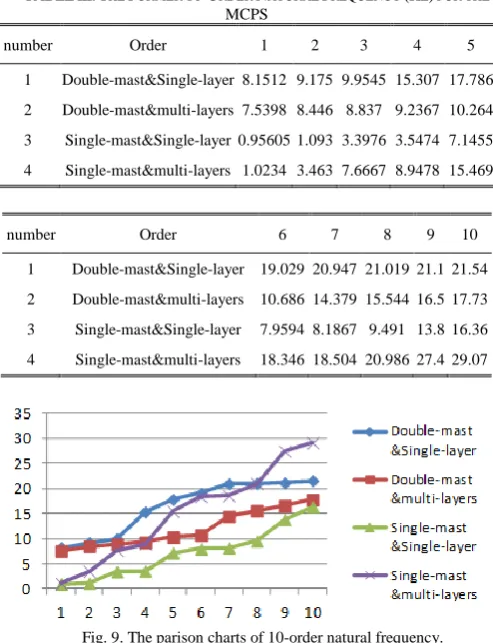
In the process of operation, MCPs are often accompanied by starting-braking, moving load, sudden loading or unloading and multi-level platforms relative movement and other dynamic conditions. Therefore, it is necessary to calculate and analyze the dynamic characteristics of each type of MCPs before use, in order to check its stability. The analysis of dynamic characteristics is modal analysis (MA), and the essence of MA is to calculate the eigenvalues and eigenvectors from the structural vibration equation. The former frequency of the structure is lower, which has a great influence on the dynamic characteristics of the structure, and the larger the order, the greater the error. So the MA only extracts the results of the former 10 natural frequency and its corresponding vibration mode, which can meet the engineering requirements well. Taking guide rails and the wall-attaching devices with 6m pitch as an example, four types of MCPs were analyzed respectively, to obtain the natural frequencies and mode shapes of the 10 orders, as shown in Table III.
TABLEIII:THE FORMER 10-ORDER NATURAL FREQUENCY (HZ) FOR THE
MCPS
number Order 1 2 3 4 5
1 Double-mast&Single-layer 8.1512 9.175 9.9545 15.307 17.786
2 Double-mast&multi-layers 7.5398 8.446 8.837 9.2367 10.264
3 Single-mast&Single-layer 0.95605 1.093 3.3976 3.5474 7.1455
4 Single-mast&multi-layers 1.0234 3.463 7.6667 8.9478 15.469
number Order 6 7 8 9 10
1 Double-mast&Single-layer 19.029 20.947 21.019 21.1 21.54
2 Double-mast&multi-layers 10.686 14.379 15.544 16.5 17.73
3 Single-mast&Single-layer 7.9594 8.1867 9.491 13.8 16.36
4 Single-mast&multi-layers 18.346 18.504 20.986 27.4 29.07
Fig. 9. The parison charts of 10-order natural frequency.
characteristics of the structure are different with the different types of the MCPs, and the natural frequency of each order varies greatly.
Among them, in the double-mast& multi-layers MCPs, the guide mast vibrates front and rear along the Y direction in the first three orders, the guide mast vibrates with the platform from the forth order to the seventh order, the platform vibrates up and down along the Z direction in the seventh order to the ninth order, and the device twists around the X axis in the tenth order; In the Single-mast& Single-layer MCPs, the platform swing left and right in the first two orders, the guide mast vibrates front and rear along the Y direction from the fifth order to the eighth order, the platform twists along X axis; Due to the working of the Single-mast& Single-layer MCPs vibrates left and right first at low frequencies of 0.9-3.5Hz which is vulnerable to wind load in the construction process and easy to lead to the Pendulum resonance. So it is necessary to set connection measures between the platform device and guide mast device or shorten the length of work platform. Low-order natural frequency and vibration characteristics are obtained through the dynamic characteristics of modal analysis, which indicates that the structural stability and safety of the Double-mast MCPs are high, the natural vibration frequency of the single-mast MCPs is low, and the platform vibrates after swinging, which leads to poor operation stability and poor operation comfort
According to the data in Table II, for the Double-mast& multi-layers, Double-mast& Single-layer and the Single-mast& Single-layer, the difference between the frequency of each order is small, and the frequency of the partial order appears the phenomenon of aggregation. So the frequency density needs further analysis. In paper [14], it is pointed out that there is no uniform standard in the discrimination about the structural frequency density. Gregory et al[15] revealed that the frequency density can be measured by the density index δ1
)
/(
)
(
1 11
f
i
f
if
i
f
i
As shown in Table III, the frequency density of the four types of MCPs.
TABLEIV: THE FREQUENCY DENSITY OF THE FORMER FOR THE FOUR
TYPES OF MCPS
frequency density δ1 1 2 3 4 5
Double-mast& Single-layer 0.059 1 0.040 8 0.211 9 0.074 9 0.033 8
Double-mast& multi-layers 0.056 7 0.022 6 0.022 1 0.052 7 0.020 1
Single-mast& Single-layer 0.543 8 0.377 7 0.077 1 0.267 1 0.085 1
Single-mast& multi-layers 0.066 7 0.513 3 0.021 6 0.336 5 0.053 9
frequency density δ1 6 7 8 9
Double-mast&Single-layer 0.0480 0.0017 0.0016 0.0107
Double-mast&multi-layers 0.1473 0.0389 0.0296 0.0362
Single-mast&Single-layer 0.0043 0.0629 0.1331 0.0290
Single-mast&multi-layers 0.0141 0.0738 0.1855 0.0842
As shown in Table IV, in addition to individual conditions (the Double-mast& Single-layer MCPs under the third order,
the Single-mast& Single-layer MCPs under the first, second and forth order, and the Single-mast& multi-layers under the second, forth and eighth order),The frequency-intensive indexes of MCPs are all small. Liu and Fan. et al [16],concluded that the structures with symmetric, quasi-symmetrical or locally symmetric tend to appear in varying degrees of intensity. The data in Table 3 are consistent with the descriptions in the literature.
V. CONCLUSIONS
1) Through the calculation of the different MCPs, the maximum stress and the maximum deformation under different working conditions are obtained, and the structural strength and stiffness meet the requirements. The most dangerous parts are often caused by the local stress for the concentrated load offset in the cantilever of platform. The larger the displacement of the cantilever, the greater the inclination of the platform is. Therefore it is recommended that the construction platform should not be allowed to be overloaded or bear too much concentrated load, and the materials should be placed on both sides of the guide mast.
2) The platform telescopic beam is extended by 1.5m in case2 and case4. The maximum stress and the maximum deformation under different working conditions of MCPs are very close. Therefore, it is significant to strictly control the load of the telescopic beam section. The telescopic part does not allow stacking of materials, with only personnel to perform on-site operations.
3) MCPs are generally load-sensitive aerial work construction equipment. The load sign need to be clearly specified before application. The material should be stacked strictly according to the platform load distribution chart.
4) MCPs are space truss system. The rods are with stress distribution. Therefore, when the construction platform is used, no one can remove the platform components and rods arbitrarily.
5) According to the dynamic analysis of structure, the stability of double mast is better than that of single mast. Suggested that the double mast of MCPs should be preferred in construction .
6) MCPs are a multi-symmetrical structure with the characteristics of large flexibility, low frequency mode dense, high degree of modal coupling and so on. The vibration needs to be controlled before the construction. That is to say, the necessary anti-vibration measures need to be set to reduce the damage to the construction platform.
ACKNOWLEDGEMENTS
REFERENCES
[1] Q. J. Jiang, “Summary on development of assembled concrete building both home and abroad,” Architecture Technology, vol. 41, no. 12, pp. 1074-1077, 2010.
[2] K. Liu, “Development and outlook of assembled precast concrete building in housing industrialization,” Building Technique
Development, vol. 42, no. 1, pp. 7-15, 2015.
[3] “2016 the 2nd session of the national construction and engineering structure of industrial construction technology exchange,”
[4] M. H. Wang, W. Z. Zhang, and R. S. Li, “Preliminary discussion on application of guide frame climbing type elevating work platform to prefabricated building construction,” Building Construction, vol. 38, no. 9, pp. 1263-1219, 2016.
[5] H. Zhang and S. L. Li, “The present status and developing trend of domestic and foreign aerial working machinery,” Construction
Mechanization, vol. 3, pp. 19-24, 2011.
[6] J. P. Chen, H. M. Li, Z. Z. Zhao et al., Construction Mechanization, vol. 9, pp. 13-15, 2010.
[7] F. X. Zhou, “Technical innovation for application of attached lifting scaffold,” Architecture Technology, vol. 43, no. 8, pp. 692-694, 2011. [8] Z. Lu, “Research on mechanics characteristics of temporarily installed suspended access equipment,” Shenyang Architecture University, 2011.
[9] J. P. Chen, H. M. Li, Z. Z. Zhao et al., “Development of lifting work platform industry and problems and challenges under the new normal,”
Construction Mechanization, pp. 23-28, 2015.
[10] X. J. Shang, F. Qiu et al., “Advanced finite element analysis method of
ANSYS structure and its application,” Beijing: China WaterPower Press, 2016.
[11] GB/T 27547-2011, “Elevating work platforms-mast-climbing work platforms,” Beijing: Standards Press of china, 2011.
[12] JGJ202-2010, “Technical code for safety of implementation scaffold practice in construction,” Beijing: Standards Press of china, 2010.
[13] GB50017-2014, “Code for design of steel structure,” Beijing: Standards Press of china, 2014.
[14] F. X. Xie and L. M. Sun, “Judging criterion of structures with closely spaced natural frequencies and its effect on control results,” Journal of
Shandong University (Engineering Science), vol. 39, no. 5, pp.
101-105, 2009.
[15] Corporation Acncal-Schwendler. [Online]. Available: http://www .mscsoftware.com/ products/new .cfm? PI =7
[16] L. J. Liu, J. L. Fan, Z. Y. Zhang et al., “Study progress in modal parameter indentification and vibation control of system with crowded modes,” Journal of Vibration and Shock, vol. 26, no. 4, pp. 109-115, 2007.