Abstract – Stingers are structures which are attached to pipelay barges in order to produce a smooth angular transition between the almost horizontal flat barge surface, where the pipelines are assembled and welded, and the catenary shape of the pipe as it descends towards the seabed. This definition has an S-lay in mind, where the pipe forms an S-shape between the barge and the seabed. The design of these structures for pipe laying purposes is a complex task because of the multiple load sources to which the stinger is subjected. There are dead loads, both of the stinger itself and the pipeline that it supports, there are inertial loads caused by the motions of the vessel, there are wave and current loads, which induce the vessel motions but which produce loads on the stinger and pipeline directly and finally there are dynamic loads induced by the interaction of the pipeline with the seabed and its lifting from the stinger supports, thus causing impact on these same supports when they re-contact them.
These loads are of nonlinear nature wherefore a time history method is the best analysis type to evaluate their effects on the stinger. One of the main problems found by engineers in the market regarding the design of this type of structure is finding a software that can handle it. There are several offshore structural packages that can deal with waves and vessel motions, but can´t handle the pipeline simultaneously, and there are also several pipeline programs that could do the job but deal with pipeline type structures only and can´t handle structural frames.
The objective of this paper is to show how one of these software systems of the second group was taken and supplemented with punching shear verifications in order to handle the job.
Index Term— Offshore Structures, Stinger, Pipelay,
Nonlinear, Time Domain, Analysis
I. INTRODUCTION
For the installation of pipelines, there are three major methods, among which the S-lay is the most common for shallow to medium water depths. lay depicts a typical S-shape of the pipeline on its way from the vessel down to the seabed. Directly after leaving the stern of the vessel it slides along a sloping ramp, controlled by tensioners located near the stern of the barge. The sloping ramp, known as a “stinger”, is a curved and open frame structure fitted with rollers, which support the pipeline, so that it may slide with little or no
1 Universidade Federal Fluminense, Brazil ([email protected]) 2 Universidade Federal Fluminense, Brazil ([email protected]) 3 Universidade Federal Fluminense, Brazil ([email protected])
4 NSG Engineering, Brazil ([email protected])
friction. The S-shape formed by the pipeline is associated to two reversed curves, which can be observed in Fig. 1 below. The first of these two curves occurs at the top and is called the overbend, where the pipeline curvature is concave. It occurs between the barge and the pipeline inflexion point and encompasses the entire stinger. The second curve is known as the sagbend and it extends from the same inflexion point all the way down to the seabed as shown in Fig. 1, along which the curvature reverses and becomes convex.
Fig. 1. Schematic of S-Lay pipeline installation method [1]
The maximum curvature is usually near the maximum water depth in the sagbend region, where the combined axial tension, bending and pressure loads must be safely sustained. The curvature in the sagbend region is controlled by the tension applied at the topside tensioners, however excessive tension can be detrimental to the section over the stinger, in the overbend, where it may result in a plastic regime of the pipe as it passes over the rollers [1].
The curvature configuration of the stinger must follow the curvature restrictions of the pipe in the overbend section, therefore the stinger length is controlled by the angular variation that the pipe must undergo. If a stinger has a very short length, it can cause further bending at the end of stinger, where even can cause local buckling at that position of the pipeline. This buckling may result in fracturing and flooding and consequently leading to a second failure at the touchdown point near the seabed.
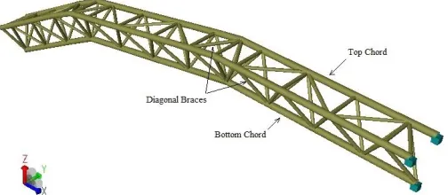
The stinger is normally defined as a space frame tubular structure (Fig. 2), whose elements are sized based on axial and shear forces in addition to bending and torsional moments. Because the space frame elements are usually made of pipes whose ends are welded, the sizing of the joints must consider also the punching shear verifications, which have become
Time History Stinger Design Considering
Multiple Load Sources to Which They Are
Subjected
common practice in the offshore industry. What really distinguishes the stinger from other on land and offshore structures is the complex loading conditions. In addition to the normal wave and current loads, to which fixed offshore structures are subjected, the motions of the barge introduce additional inertial and hydrodynamic forces, which are still supplemented by the forces induced by the pipeline, which it is supporting. The highly nonlinear nature of most of these loads makes it required to perform the corresponding analysis in the time domain.
Fig. 2. Stinger; usual space frame tubular structure [2]
II. STINGER DESIGN PROCEDURE
The design of the stinger is being treated here as that of a jacket structure according to API RP2A [3]. This code covers both resistance conditions and fatigue, but only the first is being covered in this paper.
The following load conditions are being considered in this paper:
- Forces due to dead weight and buoyancy;
- Forces due to wave and current acting directly on the stinger and pipeline;
- Inertial forces due to barge motions both on the stinger and pipeline;
- Hydrodynamic forces due to barge motions both on the stinger and on the pipeline;
- Impact forces of the pipeline on the rollers (both vertical and horizontal);
- Forces applied to the pipeline by the tensioners.
The stinger undergoes the effects of such loads, whose structural elements must optimized to withstand them. The diameter of pipe elements, their wall thickness and also the span of the roller boxes are considered to attain a proper arrangement. An initial design is performed for static conditions, in which one can establish the pipeline curvature along the stinger and the length of the stinger, so that at least the last roller is not being contacted by the pipeline. A tentative value for the tension to be considered for the tensioners will be dictated by the sagbend stresses.
The supporting conditions of the stinger can vary considerably. The example considered in this paper has taken into account a stinger which is embedded at the aft end of the barge, acting, therefore, as a cantilever beam. Another
alternative could have been as shown in figure 2, where the stinger is pinned at the barge connection, but supported by cable stays, which are normally connected about 2/3 of the stinger length away from the barge. A third alternative could have been to consider a buoyant stinger, also pinned at the barge connection, but the Brazilian success record using this alternative has not been very good, so the Brazilian national oil company tends to reject it.
Once a preliminary structural model has been established all member and joint sizes are then verified based on dynamic time history analyses using a software, which can consider and update all these forces at the end of each time step. These analyses must be performed for a desired limiting seastate, considering different periods and wave incidences.
All structural elements must be checked so the final structural sizes will be defined by these analyses. If necessary the overall stinger configuration (curvature, length and spacing between roller boxes) must be updated, which shows that the overall design is a complex iterative process.
The stinger conceived for the example presented in this paper has been pre-sized for a 1.0m OD pipeline, whose thickness is 3,5cm, which must be installed in 100m water depth. The stinger has been conceived with a triangular shaped truss and a total length of approximately 90m as shown in figure 3. The triangular shaped truss has two upper chords and one on the bottom.
All preliminary member sizes were established, as described above, based on static equilibrium results and confirmed based on the dynamic analyses defined for the local environmental conditions. A simple joint of this configuration is depicted in figure 4.
Fig. 3. Simplified stinger model for static and dynamic analyses (OrcaFlex Model)
III. ANALYSIS
Because of the large variety of dynamic force components and the different causes thereof, it is needed to find a software which can handle all of them and still provide the code stress checking required (axial bending and punching shear stresses). Offshore structural packages available in the market which can deal with waves and vessel motions, are usually unable to handle the pipeline simultaneously. Moreover, there are several pipeline software programs that could do the job but deal with pipeline type structures only and can´t handle the stinger structural frames.
None of the main offshore structural programs in the market was found able to handle the nonlinear behavior of the pipeline and all the highly nonlinear dynamic time history analyses, although all of them present automatic axial bending and punching shear stress checking. OrcaFlex [6], a software usually considered for riser and pipeline analyses and dynamic simulations of offshore installations, was found to handle all the dynamic load features related both to the stinger and the pipeline, while taking into account all the vessel motions as well. The software performs the dynamic time history analyses required by the nature of the problem and also performs the axial bending stress checks for updated forces at the end of each and every time step. The only feature it didn´t contain was the punching shear stress check, whose implementation was carried out through its programming interface called OrcFxAPI (OrcaFlex Application Program Interface).
Python as an object-orientated, dynamically typed scripting language was used to access the OrcaFlex API. The corresponding implementation was performed based on API-RP2A.
An independent verification was performed comparing the results of a static analysis carried out for the structure modeled in OrcaFlex and in Sesam GeniE [7]. The latter is a well known FEM software developed by DNV GL [4], which is used to design and analyze offshore structures.
The comparison structure was the stinger itself, which was modeled (figure 5) and analyzed as a cantilever beam subjected to self-weight in both software systems. The results of the punching shear stresses compared well in both systems.
Fig. 5. Simplified schematic of the stinger structure (SESAM GeniE model)
The verification of the stinger itself must be performed, as mentioned previously, based on analyses performed in the time domain for the operational seastate that has been
established by the owner of the vessel or of the pipeline. In this case the established seastate is one with a 2.0m significant wave height and a zero upcrossing period varying between 6 and 10 seconds. The time domain analysis performed below was run with an 8 second period. This analysis should be run for a 3 hour storm but only results for 30 minutes are presented below.
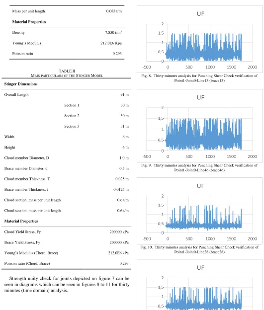
The pipeline and stinger model specifications are given in table I and II, respectively.
The results of the time history analysis are presented only for one section of the compressed chord (axial bending stress at the bottom chord at the support on the barge) – see figure 6 – and the punching shear unity checks at the joint immediately adjacent to the bottom chord support (see figure 7).
Fig. 6. Point 1 above water where pipeline leaves the lay-barge sitting on roller boxes and slides down through first section (OrcaFlex model)
Fig. 7 – Joints and members on the buoy simulated for stinger model (SESAM
GeniE model)
TABLEI
PIPELINE SPECIFICATION FOR DYNAMIC ANALYSIS
Parameter Value
Overall Length 550 m
Section 1 200 m
Section 2 150 m
Section 3 150 m
Target Segment Length 1 m
Diameter 1 m
Mass per unit length 0.083 t/m
Material Properties
Density 7.850 t/m3
Young’s Modulus 212.0E6 Kpa
Poisson ratio 0.293
TABLEII
MAIN PARTICULARS OF THE STINGER MODEL
Stinger Dimensions
Overall Length 91 m
Section 1 30 m
Section 2 30 m
Section 3 31 m
Width 6 m
Height 6 m
Chord member Diameter, D 1.0 m
Brace member Diameter, d 0.5 m
Chord member Thickness, T 0.025 m
Brace member Thickness, t 0.0125 m
Chord section, mass per unit length 0.6 t/m
Chord section, mass per unit length 0.6 t/m
Material Properties
Chord Yield Stress, Fy 200000 kPa
Brace Yield Stress, Fy 200000 kPa
Young’s Modulus (Chord, Brace) 212.0E6 kPa
Poisson ratio (Chord, Brace) 0.293
Strength unity check for joints depicted on figure 7 can be seen in diagrams which can be seen in figures 8 to 11 for thirty minutes (time domain) analysis.
Fig. 8. Thirty minutes analysis for Punching Shear Check verification of Point1-Joint0-Line13 (brace13)
Fig. 9. Thirty minutes analysis for Punching Shear Check verification of Point1-Joint0-Line46 (brace46)
Fig. 10. Thirty minutes analysis for Punching Shear Check verification of Point1-Joint0-Line28 (brace28)
IV. SUMMARY AND CONCLUSIONS
This paper presented a design summary of a special offshore structure known as a stinger, which is applied in the offshore industry to control the curvature of rigid pipelines along the section where they are leaving the lay-barge and sliding into the water during their installation operation.
It has been shown that the design difficulty of such a structure is related to multiple different loading conditions to which these structures are subjected, mostly of nonlinear nature and because of which they must be analyzed based on the results of dynamic time history analyses.
One of the problems encountered to perform such analyses is finding an adequate software that can handle all these different load conditions, the nonlinearity of the pipeline problem and the stress checking, which must encompass not only the traditional axial bending stresses, but also those due to punching shear, since most stringers are usually build with tubular member frames.
Although there are several different structural offshore programs on the market, which can handle jacket type structures very well, unfortunately the nonlinear nature of the pipeline is not necessarily available for this type of program, so finding one which can suit all the different required features was found to be a challenging task.
The software used for the analyses performed in this paper is a dynamic simulation program called OrcaFlex, which had all the required features except the punching shear stress checking. This software does, however, allow the user to supplement results with external calculations, so the punching shear checks, based on API-RP2A [3] were implemented in OrcaFlex [6] and tested by comparison with results produced in SESAM [9].
Finally sample runs of the dynamic time history analyses required to design not only the stinger but also the pipeline installation problem presented in order to show the reader how they are performed.
As a suggestion for future developments a similar implementation is required for the fatigue analysis of the stinger, which is part of the design of the stinger.
ACKNOWLEDGMENT
I would like to thank CAPES (Coordenadoria de Aperfeiçoamento de Pessoal de Nível Superior, a government agency linked to the Brazilian Ministry of Education, that is in charge of promoting high standards for post-graduate courses in Brazil) for the financial support granted, which has made this research possible.
REFERENCES
[1] Kyriakides, S., Corona, E., Mechanics of Offshore Pipelines, Volume 1: Buckling and Collapse, First Edition, Offshore Facilities and Pipeline Installation Methods, Elsevier, 2007, pp/ 15-58
[2] DP Pipe-lay Vessel ‘Sampson’, Engineering - Pipelay Package; Scivita Inc.; Drilling, Pipelay and Lifting Solutions; 2012; (Operator) Carvel http://www.scivita.com/engineering.html [3] American Petroleum Institute. 'Recommended practice for
planning, designing and constructing fixed offshore platforms -
working stress design', API RP2A-WSD, 21st edition, December 2014
[4] DET NORSKE VERITAS Offshore Standard, DNV - OS - C201 - Structural Design of Offshore Units (WSD Method), April 2012 [5] Deep Water Challenges, Pipeline Installation Case; Seminar
Nasional Oceano ITS, DeepLay Energy Service, 28.03.2011 [6] OrcaFlex 10.1b / Help, Orcina Ltd. 1987 – 2016
https://www.orcina.com/
[7] SESAM GeniE / Help, DNV GL – Software
https://www.dnvgl.com/services/offshore-and-marine-structural-engineering-sesam-genie-1096
[8] A. A. Golbini Mofrad, Master Thesis, “Design of Stinger Structures
![Fig. 1. Schematic of S-Lay pipeline installation method [1]](https://thumb-us.123doks.com/thumbv2/123dok_us/1352109.1643796/1.612.314.561.301.444/fig-schematic-s-lay-pipeline-installation-method.webp)
![Fig. 2. Stinger; usual space frame tubular structure [2]](https://thumb-us.123doks.com/thumbv2/123dok_us/1352109.1643796/2.612.47.298.172.347/fig-stinger-usual-space-frame-tubular-structure.webp)