IJSRSET1738158 | Received : 15 Nov 2017 | Accepted : 06 Dec 2017 | November-December-2017 [(3)8: 468-474]
© 2017 IJSRSET | Volume 3 | Issue 8 | Print ISSN: 2395-1990 | Online ISSN : 2394-4099 Themed Section: Engineering and Technology
468
Result of Analysis of Power System Oscillation Damping & Voltage
Stability Improvement Using SSSC in A Multi-Machine System
1
Amit Kumar,
2Pardeep Nain
1
M.Tech Scholar ,
2Assistant Professor
EE Department, Om Institute of Technology & Management, Hisar, Haryana, India
ABSTRACT
Interconnection of electric power systems is becoming increasingly widespread as part of the power exchange between countries as well as regions within countries in many parts of the world. There are numerous examples of interconnection of remotely separated regions within one country. In cases of long distance AC transmission, as in interconnected power systems, care has to be taken for safeguarding of synchronism as well as stable system voltages, particularly in conjunction with system faults. With series compensation, bulk AC power transmission over very long distances (over 1000 km) is a reality today As a result, many power network operators are taking steps to add supplementary damping devices in their systems to improve the system security by damping these undesirable oscillations. With the advent of voltage sourced converter-based series compensation, AC power system interconnections can be brought to their fullest benefit by optimizing their power transmission capability, safeguarding system stability under various operating conditions and optimizing the load sharing between parallel circuits at all times.
Keywords : Static Synchronous Series Compensator (SSSC), Voltage Stability, Power Oscillations Damping (POD),
FACTS.
I.
INTRODUCTION
Although electricity is a highly engineered product, it is increasingly being considered and handled as a commodity. Thus, the focus on the quality of power delivered is also greater than ever. Series capacitive compensation of power transmission lines is an important and the most economical way to improve power transfer capability, especially when large amounts of power must be transmitted through long transmission lines. However, one of the impeding factors for the increased utilization of series capacitive compensation is the potential risk of Subsynchronous Resonance (SSR), where electrical energy is exchanged with turbine-generator shaft systems in a growing manner which can result in shaft damage . A typical time response of a turbine-generator shaft torsional torque during and after clearing a fault on a series capacitive compensated transmission line in the presence of the SSR phenomenon. It is worth noting here that this shaft is designed to withstand a maximum torsional torque of 2 per unit. Another limitation of series capacitive compensation is its inability to provide adequate damping to power system oscillations after clearing system faults
II.
STATIC SYNCHRONOUS SERIES
COMPENSATOR (SSSC)
The SVS-based series compensator, called Static Synchronous Series Compensator (SSSC) was proposed by Gyugyi in 1989 within the concept of using converter-based technology uniformly for shunt and series compensation as well as for transmission angle control.
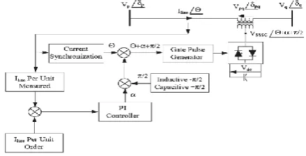
2.1 Phase Control Technique for SSSC
change in the dc capacitor voltage, and consequently causing a change in the converter output voltage magnitude .
Fig 2.1. Functional control diagram for the phase-controlled SSSC
2.2 PWM Technique
SSSC is modeled as a three-phase, PWM-controlled two-level VSC. The SSSC is modeled in detail, based on an ideal representation of the converter valves and diodes. RC parallel snubber circuits are used to reduce numerical oscillations due to switching, while a series inductance is employed at the converter output to smooth the output current. The series transformer is modeled as an ideal, three-phase, two-winding, Y-Δ connected transformer.
Fig 2.2. Functional control diagram for the PWM-controlled SSSC
2.3 Structure of SSSC-based Damping Controller
1.One of the structures used in this thesis to modulate the SSSC injected voltage is the lead-lag structure as shown in fig.5.11. This structure consists of a gain block, washout block and two stage lead-lag block. The two stage lead-lag block provides the appropriate phase-lead characteristics to compensate for the phase lag between input and the output signals. The washout block acts as a high pass filter to allow signals associated with oscillations to pass as it is. The inputs to the POD controller are the bus voltage at Bus no.2 and the current flowing in Line 1.The Power Oscillation Damping Controller takes input as Vabc ,Iabc& it convert it as power.
Figure 2.3. POD controller design structure
III.
SIMULINK MODELS
Fig -3.1 Complete Simulation model of test system
3.1 Sub System model:-
3.1.1. POD Model –
Figure 3.2. Simulink Model of POD controller
3.2 SYMMETRICAL FAULT ANALYSIS
3.2.1. CASE 1: Power flow under normal condition (when POD is OFF, SSSC is by passed and no fault is applied):-
Fig. 3.3. X-axis Show time in sec. and Y-axis Show Active Power in Kw at bus no. 2 During Normal condition (No fault). The Transient Die out in Settling Time (4T).
Fig. 3.4. X-axis Show time in sec. and Y-axis Show Positive Sequence voltage at all buses During Normal condition (No fault). The Transient Die out soon.
Fig. 3.5. X-axis Show time in sec. and Y-axis Show Active Power in Kw measured at all buses During Normal condition (No fault). The Transient Die out in Settling Time (4T).
Fig. 3.6. X-axis Show time in sec. and Y-axis Show Reactive Power in Mvar at all buses During Normal condition (No fault). The Transient Die out in 2T.
3.2.2 CASE 2: SSSC under a three phase fault when POD is OFF
In this condition POD is kept „off‟. Under this condition the effect on power flow at bus no. 2 is shown in fig. 3.7. The fault clears at 0.5 sec as shown in fig. 3.7. In case 2 initially Vqref is set to zero. At 2 sec. it is set to -0.08pu which makes SSSC to operate in inductive mode. At 6 sec. Vqref is set to 0.08 pu which operates SSSC in capacitive mode. A three phase fault is applied at Bus no. 4 at 0.33 sec. which lasts for 10 cycles. Figure 3.7 shows the power oscillations observed at bus no.2 . The inductive and capacitive mode of operation can be observed easily. Fig 3.8 shows that how the injected voltage Vqinj follow the reference voltage Vqref.
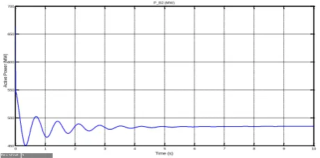
Fig. 3.7. X-axis Show time in sec. and Y-axis Show Active Power in Kw at bus no. 2 During Abormal condition ie fault. The Transient Die out in 8T (Almost double to normal case).
Fig. 3.8. X-axis Show time in sec. and Y-axis Show that how the injected voltage Vqinj follow the reference voltage Vqref.
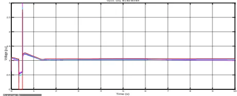
Fig. 3.9. X-axis Show time in sec. and Y-axis Show Positive sequence votltage at all buses During Abormal condition ie fault. The Transient Die out in 1.5 T.
0 1 2 3 4 5 6 7 8 9 10
450 500 550 600 650 700 Time (s) A ct ive P ow er (M W ) P_B2 (MW)
0 1 2 3 4 5 6 7 8 9 10
0.7 0.8 0.9 1 1.1 1.2 1.3 Time (s) Vo lta ge (p .u )
Vpos. seq. B1 B2 B3 B4
0 1 2 3 4 5 6 7 8 9 10
200 400 600 800 1000 1200 1400 1600 1800 Time (s) A ct ive p o w e r (M W )
P B1 B2 B3 B4 (MW)
0 1 2 3 4 5 6 7 8 9 10
-900 -800 -700 -600 -500 -400 -300 -200 -100 0 TIme (s) R ea ct ive P ow er (M V ar )
Q B1 B2 B3 B4 (Mvar)
0 1 2 3 4 5 6 7 8 9 10
100 200 300 400 500 600 700 Time (s) A ct ive P o w e r (M W ) P_B2 (MW)
0 1 2 3 4 5 6 7 8 9 10
-0.1 -0.08 -0.06 -0.04 -0.02 0 0.02 0.04 0.06 0.08 0.1 Time (s) Vo lta ge (p .u )
Vqinj Vqref (pu)
0 1 2 3 4 5 6 7 8 9 10
0 0.5 1 1.5 2 2.5 3 Time (s) Vpos. seq. B1 B2 B3 B4
Fig. 3.10. X-axis Show time in sec. and Y-axis Show Active Power in Kw measured at all buses During Abormal condition ie fault. The Transient Die out in 2T.
Fig. 3.11. X-axis Show time in sec. and Y-axis Show Reactive Power in Mvar Measured at all buses During Abormal condition ie fault.
Fig. 3.12. X-axis Show time in sec. and Y-axis Show Modulation index During Abormal condition ie fault.
3.2.3 CASE 3: Test system with SSSC under a three phase fault and POD is ON :-
In this case, test system is kept under a symmetrical fault at 0.33 sec. and POD is kept on. The dynamic response of SSSC under this condition is shown below. As compare to fig.3.7 the power oscillations are removed very effectively. The output results illustrate that the power system oscillations are damped out very rapidly with the help of SSSC based damping controllers in few seconds.
Fig. 3.13. X-axis Show time in sec. and Y-axis Show Active Power in Kw measured at buses no.2 During Abormal condition ie fault and POD is ON. As compare to fig.3.7 the power oscillations are removed very effectively. The output results illustrate that the power system oscillations are damped out very rapidly with the help of SSSC based damping controllers in few seconds.
Fig. 3.14. X-axis Show time in sec. and Y-axis Show SSSC dynamic response for Voltage at three phase fault During Abormal condition ie fault and POD is ON. As compare to fig.3.8 the power oscillations are removed very effectively. The output results illustrate that the power system oscillations are damped out very rapidly with the help of SSSC based damping controllers in few seconds.
Fig. 3.15. X-axis Show time in sec. and Y-axis Show Positive Sequence Voltage at all buses During Abormal condition ie fault and POD is ON. As compare to fig.3.9 the power oscillations are removed very effectively. The output results illustrate that the power system oscillations are damped out very rapidly with the help of SSSC based damping controllers in few seconds.
Fig. 3.16. X-axis Show time in sec. and Y-axis Show Active power measured at all buses in kw at all buses During Abormal condition ie fault and POD is ON. As compare to fig.3.10 the power oscillations are removed
0 1 2 3 4 5 6 7 8 9 10
-3000 -2000 -1000 0 1000 2000 3000 Time (s) Act ive P ow er (M W )
P B1 B2 B3 B4 (MW)
0 1 2 3 4 5 6 7 8 9 10
-8000 -6000 -4000 -2000 0 2000 4000 Time (s) Q B1 B2 B3 B4 (Mvar)
R ea ct ive P ow er (M Va r)
0 1 2 3 4 5 6 7 8 9 10
0 0.1 0.2 0.3 0.4 0.5 0.6 0.7 0.8 Time (s) M ou la tio n In de x
<mo d Ind e x>
0 1 2 3 4 5 6 7 8 9 10
200 300 400 500 600 700 800 Time (s) A ct ive P o w e r (M W ) P_B2 (MW)
0 1 2 3 4 5 6 7 8 9 10
-0.2 -0.15 -0.1 -0.05 0 0.05 0.1 0.15 Time (s) V ol tg e (p .u )
Vqinj Vqref (pu)
0 1 2 3 4 5 6 7 8 9 10
0 0.5 1 1.5 2 2.5 3 Time (s) Vo lta ge (p .u )
Vpos. seq. B1 B2 B3 B4
0 1 2 3 4 5 6 7 8 9 10
-3000 -2000 -1000 0 1000 2000 3000 Time (s) Act ive P ow er (M W )
very effectively. The output results illustrate that the power system oscillations are damped out very rapidly with the help of SSSC based damping controllers in few seconds.
Fig. 3.17. X-axis Show time in sec. and Y-axis Show Reactive power in Mvar measured at all buses During Abormal condition ie fault and POD is ON. As compare to fig.3.11 the power oscillations are removed very effectively. The output results illustrate that the power system oscillations are damped out very rapidly with the help of SSSC based damping controllers in few seconds.
Fig. 3.18. X-axis Show time in sec. and Y-axis Show Modulation index During Abormal condition ie fault and POD is ON. As compare to fig.3.12 the power oscillations are removed very effectively. The output results illustrate that the power system oscillations are damped out very rapidly with the help of SSSC based damping controllers in few seconds.
It can be Seen From all of these figure that the POD Result is a Relatively Better System transient Response in term of the settling time.
IV.
CONCLUSIONS
This thesis analyze the performance of a SSSC in a multi machine system in the presence of different faults is considered. The output results illustrate that the power system oscillations are damped out very rapidly with the help of SSSC based damping controllers in few seconds. The study reveals that SSSC is proficient to
enhance the power flow through the transmission line by injecting a fast changing voltage in series with the line. The injected voltage is in quadrature with line current and hence it can provide both inductive and capacitive compensation. PWM based and phase controller have both disadvantages and advantages, which makes the design process somewhat complicated. The dc voltage pre-set value in PWM-based controllers has to be carefully selected. As the modulation ratio lies between zero and one, the dc voltage should not be lower than the maximum of the requested SSSC output phase voltage in order to obtain proper control. On the other hand, if the dc side voltage is too high, the rating of both the GTO valves and dc capacitor has to be increased, which means higher installation costs. Not only that, a higher dc side voltage means a lower amplitude modulation ratio, and the lower modulation ratio results in higher harmonic distortion. Phase control allows the dc voltage to change according to the power system conditions, which is clearly advantageous, but it requires a more complicated controller and special and costly series transformers.
V.
REFERENCES[1]. O. Ziaee, F. F. Choobineh, "Optimal location- allocation of TCSC devices on a transmission network", IEEE Trans. on Power Systems, vol. 32, no. 1, pp. 94-102, Jan. 2017.
[2]. Ummeaiman V. Aleem, CH. Mallareddy, Spruha S. Pitre, Samarpita S. Bakshi ,Static Synchronous Series Compensator (SSSC) as Stability Booster of a Power System,2017 by IJETI Journal volume-46,Number-6.
[3]. D. A. Ingole, Prof. Dr. V .N. Gohokar; Voltage Stability Improvement In Multi-bus System Using Static Synchronous Series Compensator 1st International Conference on Power Engineering, Computing and CONtrol, PECCON-2017, 2- 4 March 2017, VIT University, Chennai Campus. [4]. A. Ganga Dinesh Kumar, N.V. Ramana ,
Integrating SSSC with Variable Structure Observer based Optimal Controller for Damping Frequency Oscillations of Deregulated Power System ; International Journal of Applied Engineering Research ISSN 0973-4562 Volume 12, Number 14 (2017) pp. 4191-4198 © Research India Publications.
[5]. Abhinav L. Purkar, Prof. Prasanna D Bharadwaj; Improvement of Multi-Machine Power System Stability Using SSSC ;International Journal for Research in Applied Science & Engineering Technology (IJRASET) ; Volume 4 Issue IV, April 2016 IC Value: 13.98 ISSN: 2321-9653 .
0 1 2 3 4 5 6 7 8 9 10
-8000 -6000 -4000 -2000 0 2000 4000
Time (s)
R
e
a
ct
ive
P
o
w
e
r
(M
V
a
r)
Q B1 B2 B3 B4 (Mvar)
0 1 2 3 4 5 6 7 8 9 10
0 0.1 0.2 0.3 0.4 0.5 0.6 0.7 0.8 0.9 1
Time (s)
M
o
d
u
la
ti
o
n
I
n
d
e
x
[6]. Abhinav L. Purkar, Prof. P. D. Bharadwaj ; Enhancement of Multi Machine PowerSystem Stability Using SSSC with Power Oscillation Damping (POD) Controller ; Print ISSN : 2395-1990, Online ISSN : 2394-4099, Volume 2, Issue 3, pp.822-827, May-June-2016.
[7]. C. Udhaya Shankar, Dr. Rani Thottungal, Mythili,"voltage stability improvement and power oscillation damping using static synchronous series ; compensator (SSSC)", IEEE Sponsored 9th International Conference on Intelligent Systems and Control (ISCO)2015.
[8]. R Visakhan, Rahul R, Asha Anu Kurian,"Comparative study of PSS and FACTS -POD for power system performance enhancement", 2015 IEEE Instrumentation, Control and Computing (PICC).
[9]. Maninder rohal , Mr.Ravi,"Application of SSSC Based Power Oscillation Damping Controller for Transient Stability Enhancement of Multimachine system for Unsymmetrical Faults", Power India International Conference (PIICON), 2014 6th IEEE.
[10]. Shashi Gandhar, Jyoti Ohri, Mukhtiar Singh,"Application of SSSC for Compensation Assessment of Interconnected Power System"2014 IEEE 6th India International Conference on Power Electronics (IICPE).
[11]. C.Anitha, P.Arul "Enhancement of Voltage Stability in Transmission System Using SSSC "International Conference on Circuit, Power and Computing TechnologiesICCPCT2014.
[12]. Khadanga, R.K., Satapathy, J.K. “Gravitational search algorithm for the static synchronous series compensator based damping controller design” Students' Technology Symposium (TechSym), 2014 IEEE, Feb. 28 2014-March 2 2014 Page(s):356 - 361
[13]. Kotwal, C., Sangala, U. ; Pillai, G.N. “Improving power oscillation damping using static synchronous series compensator” Published in: India Conference (INDICON), 2013 Annual IEEE, 13-15 Dec. 2013Page(s):1 – 6.
[14]. Tossaporn Surinkaew, Issarachai Ngamroo and Worawat Nakawiro,"Robust Power Oscillation Damper Design for DFIG-based Wind Turbine", 2013 10th International Conference on
[15]. S Arun Kumar, C Easwarlal, M Senthil Kumar,"Multi Machine Power System Stability Enhancement Using Static Synchronous Series Compensator", 2012 International Conference on Computing, Electronics and Electrical TechnologiesICCEET].
[16]. M. Farahani ; Damping of subsynchronous oscillations in power system using static synchronous series compensator ; Volume: 6, Issue: 6, June 2012; International Conference on
Computing, Electronics and Electrical TechnologiesICCEET].
[17]. Unal, I.Rai, D., Faried, S.O. “Damping power system oscillations using an SSSC-based hybrid series capacitive compensation scheme” PowerTech, 2011 IEEE Trondheim, 19-23 June 201, Page(s):1 – 6.
[18]. Borre, A.C. Ortiz, A. ,Watanabe, E.H. & Sulkowski, W. “Synchronous generator power oscillations damped by using TCSC or SSSC working as a variable reactance” International Conference on Electrical Machines and Systems (ICEMS), 2011 I20-23 Aug. 2011, Page(s):1-6. [19]. Faridi, M. Maeiiat, H. ; Karimi, M. ; Farhadi, P.
“Power system stability enhancement using static synchronous series compensator (SSSC)” Computer Research and Development (ICCRD), 2011 3rd International Conference on (Volume:3 )11-13 March 2011, Page(s):387 – 391.
[20]. Therattil, J.P, Panda, P.C. “Improving dynamic stability of a power system using adaptive Static Synchronous Series Compensator” TENCON 2011 - 2011 IEEE Region 10 Conference , 21-24 Nov. 2011, Page(s): 928 – 932.
[21]. Vishwakarma, S. Tripathi, R.K. “Transient energy dissipation and damping improvement using STATCOM & SSSC” Power, Control and Embedded Systems (ICPCES), 2010 International Conference on, Nov. 29 2010-Dec. 1 2010, Page(s):1 – 4.
[22]. H. Taheri , S. Shahabi, Sh. Taheri, A. Gholami "Application of Synchronous Static Series Compensator (SSSC) on Enhancement of Voltage
Stability and Power Oscillation
Damping".EUROCON 2009, EUROCON '09. IEEE.
[23]. Li Juan , Dong Sheng ; Zhou Xingfu “A Nonlinear Control Approach to Increase Power Oscillations Damping by SSSC” Computer and Electrical Engineering, 2008. ICCEE 2008. International Conference on, 20-22 Dec. 2008 Page(s):734 – 738.
[24]. Anil C. Pradhan and P. W. Lehn “Frequency-Domain Analysis of the Static Synchronous Series Compensator” IEEE TRANSACTIONS ON POWER DELIVERY, VOL. 21, NO. 1, JANUARY 2006.
[25]. S. Salem and V. K. Sood, “Modeling of SSSC with EMTP RV,” IEEE ISIE 2006, July 9-12, 2006, Montréal, Québec, Canada.
[26]. Fawzi. A. Rahman Al Jowder,and Boon-Teck Ooi “Series Compensation of Radial Power System by a Combination of SSSC and Dielectric Capacitors” IEEE TRANSACTIONS ON POWER DELIVERY, VOL. 20, NO. 1, JANUARY 2005.
Combination of SSSC and Dielectric Capacitors,” IEEE Transactions on Power Delivery, Vol. 20, No. 1, January 2005, pp. 458-465.
[28]. Chandrakar, V.K., Kothari, A.G. “Fuzzy logic based static synchronous series compensator (SSSC) for transient stability improvement ” Electric Utility Deregulation, Restructuring and Power Technologies, 2004. (DRPT 2004). Proceedings of the 2004 IEEE International
Conference ,Volume:1, 5-8 April
2004Page(s):240 - 245 Vol.1.
[29]. R. Mohan and R. K. Varma, Thyristor-Based FACTS Controllers for Electrical Transmission Systems. Piscataway, NJ: IEEE Press, 2002 [30]. N. G. Hingorani and L. Gyugyi, Understanding
FACTS: Concepts and Technology of Flexible AC Transmission Systems. New York: IEEE Press, 2000.
[31]. L. Sunil Kumar and A. Ghosh, “Modeling and control design of a static synchronous series compensator,” IEEE Trans. Power Del., vol. 14, no. 4, pp. 1448–1453, Oct. 1999.
[32]. R.Billinton, M. Fotuhi-Firuzabad and S.O. Faried,"Power System Reliability Enhancement using a Thyristor Controlled Series Capacitor,” IEEE Transactions on Power Systems, Vol. 14, No. 1, February 1999, pp. 369-374.
[33]. Y.H. Song and A.T. Johns, Flexible AC Transmission Systems (FACTS), London, Institution of Electrical Engineers, 1999.
[34]. R. Mihalic, and I, Papic “Mathematical Models and Simulation of a Static Synchronous Series Compensator”,IEEE Power Tech‟99 Conference, BPT99-315-42, August 1999. Budapest, Hungary [35]. K. K. Sen “SSSC – Static Synchronous Series
Compensator: Theory, Modeling, And Applications”, IEEE Transactions on Power Delivery, Vol. 13, No. 1, pp. 241 – 246, January 1998.
[36]. K. K. Sen “SSSC – Static Synchronous Series Compensator: Theory, Modeling, And Applications”, IEEE Transactions on Power Delivery, Vol. 13, No. 1, pp. 241 – 246, January 1998.
[37]. Gyugyi, Laszlo, Schauder, Colin D. ; Sen, K.K. “Static synchronous series compensator: a solid-state approach to the series compensation of transmission lines” Power Delivery IEEE Transaction(Volume:12 , Issue: 1 , )Jan 1997Page(s):406 – 417.
[38]. P.M. Anderson and R.G. Farmer, Series Compensation of Power Systems, PBLSH!, 1996. [39]. N. Mohan, T.M. Undeland, W.P. Robbins, Power
Electronics: Converters, applications, and design, Second Edition, John Wiley & Sons, 1995. [40]. P. Kundur, Power System Stability and Control,
New York, McGraw-Hill, 1994.