Compensating Device Inertia for 6-DOF Haptic
Rendering
Jilin Zhou
∗, Franc¸ois Malric
∗, Emil M. Petriu
†, and Nicolas D. Georganas
∗‡Distributed and Collaborative Virtual Environments Research Laboratory (DISCOVER)
School of Information Technology and Engineering (SITE), University of Ottawa
Ottawa, Canada
∗
jzhou/fmalric/[email protected],
†[email protected]
Abstract—In this paper, the importance of the user’s primary holding pivot point on the end effector of a haptic interface is discussed. Both theoretical analysis and experimental results demonstrate that this holding pivot point is critical for the correct perception of the haptic properties assigned to the virtual objects. We also study the physical inertia effects of the end effector on the non-uniform stiffness perception of simulated virtual objects. To the best of our knowledge, no such combined consideration of holding pivot point and device structure related inertia has so far been made for works in 6-DOF haptic rendering. We have instrumented the end effector of a haptic interface with a membrane potentiometer to measure the user’s primary holding pivot point in real-time. Accordingly, a preliminary adaptive feedback method is developed to render the appropriate forces/torques to compensate for the effects of the end effector’s inertia on the haptic stiffness perception.
Index Terms—6-DOF haptic rendering, tip inertia, holding pivot point, collision point.
I. INTRODUCTION ANDMOTIVATION
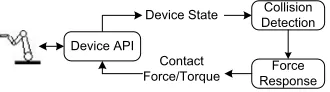
Haptics, originally from the Greek verb ”haptesthai” (to touch), pertains to the sense of tactile and kinesthetic touch. Since the emergence of the Phantom series of haptic interfaces in the middle 1990s, haptics has been a fast-growing interdis-ciplinary research field in the areas of psychophysics, haptic interface design, and particularly the replication of real-world interacting forces in virtual reality (VR) applications. Haptic rendering refers to the process of computing and exhibiting interaction forces between a virtual tool, which directly follows the movements of the device’s end effector held by the user, and other simulated virtual objects [1]. As shown in Fig. 1, haptic rendering includes two main modules: collision detection and force response. The collision detection module verifies the collision status and determines the contact details between the virtual tool and the interacting objects, while the force response module computes the interacting forces. The haptic rendering control loop is required to run at a high rate, around 1 KHz, to give the user a faithful and continuous haptic perception.
One of the complexities in haptic rendering is the repre-sentation of the real tool inside the virtual environment (VE). ‡N.D. Georganas holds a C´atedra de Excelencia at the Univ. Carlos III de Madrid and is visiting researcher at IMDEA Networks, on leave from the School of Information Technology and Engineering, University of Ottawa.
Collision Detection
Force Response Device State
Contact Force/Torque Device API
Fig. 1: Typical haptic rendering process
For haptic interfaces generating only translational force, the tool is usually modeled by a zero-mass point or sphere with a small radius for the collision detection [2], [3]. This point-based method is adequate for applications where tool-object interactions can be sufficiently described as a point-surface contact. But many of our real-world tasks do not fall into this contact paradigm. For instance, when we tighten a bolt using a wrench, the contacts between the bolt and the wrench may be a point-surface contact, a line-surface contact, a surface-surface contact, or a combination of them. There are two primary distinctions in these general tool-object operations. The first one is that the contact point can be anywhere on the tool. The second one is that the torque generated by the contact force passes important information to the user about the interaction and is essential for the completion of the task. Therefore, to simulate these general operations, the tool should be modeled as its real geometric shape in the process of haptic rendering. This 6-DOF haptic rendering not only increases the computational complexity of the collision detection but also requires the devices with the capability of providing both translational force and rotational torque. Current research on 6-DOF haptic rendering mainly focuses on the real-time collision detection and contact determination for complex objects with multiple point interaction.
In this paper, we will discuss the effects of the user’s holding points on the end effector for the perception of the force/torque feedback from the VE. In the real-world, the objectives of the task usually determine how the tool is held, the number of fingers involved, and the forces exerted by the different fingers. The force exerted on the tool from each finger is also generally time-varying. In addition, the force/torque felt by the user while using a tool is also related to the hand holding posture and its relative configuration on the tool. For instance, the prismatic holding postures for precision grip as shown in
Fig. 2: Prismatic handling posture adapted from [4]
Fig. 2 involve grasping a tool between the tip of the thumb and of the index finger, and sometimes also the middle finger [4]. In such a way, there is precise control of the position of the tool and of the grasping forces [5]. Indeed, to derive a control point for the rendering of feedback force/torque for these multi-points and time-varying holding postures is challenging. Currently, the user holding points on the end effector is either not considered or just assumed to be fixed. This may not be important for general virtual touching applications, but for some applications such as medical simulations to train students on how to make a cut with a scalpel or tele-operated surgery, the realistic haptic rendering of the interaction is extremely important because the decision for future steps is heavily relied on the current haptic feedback [6].
We will also discuss the effects of physical inertia of the end effector (device inertia) on the rendering of haptic feedback. In any haptic simulations, we always hope that the requested force/torque can be faithfully transmitted to the user through the equipped joint motors. However, some factors which may affect this include motor dynamics, current amplifier charac-teristics, and arm structure [7]. Through experiments, we have found that the device inertia affects the perceived stiffness of the simulated objects non-uniformly. We propose an adaptive method to compensate for it by measuring the primary holding point in real-time and by modifying the rendered force/torque based on the relative configuration between the virtual collision point and the primary holding point. Our preliminary results show the effectiveness of the method.
The rest of this paper is organized as follows. Section II discusses the role of the holding point in current 6-DOF haptic rendering algorithms. The maximum linear stiffness at the collision point is also discussed. Section III describes the problems and the proposed method for the device inertia compensation. Section IV describes the experiment procedure and the results. Section V concludes the paper and describes some future work.
II. HOLDING POINT IN 6-DOF HAPTIC RENDERING
In this section, the role of the user’s holding point for 6-DOF haptic simulation is discussed from two perspectives: the virtual holding point on the virtual tool and the real holding point (control point) on the end effector of the device. The maximum allowed linear stiffness of the collision point in 6-DOF haptic rendering is also described.
A. Virtual holding point
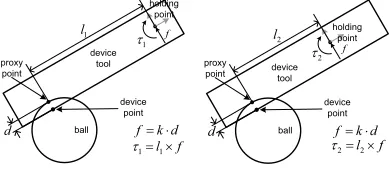
For 6-DOF haptic rendering, there are two main ways to compute the force/torque feedback: direct rendering and simulation-based rendering [8]. Let us take the stick-on-ball application shown in Fig. 3 as an example in which the stick is the virtual tool held by the user and the ball is the interacting virtual object. With direct rendering, when the stick is penetrating the ball, the point on the surface of the stick (collision point) with the deepest penetration depth and correspondent contact point on the surface of the ball (proxy point) are first determined. A spring force f is then calculated between these two correspondent points as the translational force feedback component. At the same time, forcef will generate a torque/moment component around the holding point. This feedback force/torque pair will push the stick out of the ball so that the user feels the collision and the stiffness of the ball. Other haptic properties such as frictions can be simulated by the perturbation of the forcefaccording to some physical laws.
device tool
ball
holding point
device point proxy
point
1 l
1
W
d k f
f l1u
1
W
d
f
device tool ball
holding point
device point proxy
point
2 l
2
W
d k f
f l2u
2
W
d
f
Fig. 3: Direct haptic rendering
With simulation-based rendering, the force/torque feedback is generated using a rigid-body simulation of the virtual tool as shown in Fig. 4. For this stick-on-ball application, the motion of the end effector held by the user is converted to a force/torque pair acting on the virtual stick (virtual tool) by setting a viscoelastic coupling in between. The same coupling force/torque is combined with the collision force/torque between the virtual stick and the virtual ball. The resultant force/toque is then applied on the virtual stick and the Newton’s laws for linear and rotational motions determine the resulting motion of the virtual stick. The final feedback force/torque to the user is then calculated as the viscoelastic coupling between the updated position/orientation of the virtual stick and the current position/orientation of the end effector (device tool). It is clear now that the holding point of the user on the end effector is an explicit parameter. With direction rendering, the location of the holding point determines the direction and the magnitude of the feedback torque, while with simulation-based haptic rendering; both the force and the torque are affected.
Virtual tool
device tool
ball
holding point
Virtual tool
device tool
ball holding
point
Fig. 4: Simulation-based haptic rendering
a
Spatial frame
z x
y 3
W
5W
4
W
T
35
T
4
T
z xy
Tool frame
Center of distal stage (tip of end effector)
Control point
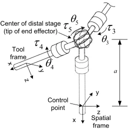
Fig. 5: End Effector linkage of Freedom 6S hand controller
of the holding point and the user’s real-world experience of such operations, the user knows in advance what kind of rotational movement to expect from a given collision. This matched haptic and visual feedback of the holding point further improves the level of realism of the tool-object interaction.
B. Real holding point
After a feedback force/torque pair Ft = [ft τt]T from
the simulation is determined, a correspondent motor torque
τ to render on the end effector has to be calculated. In this section, we discuss the effects of the user’s real holding point on the end effector for the perception of the requestedFt. A
6-DOF haptic interface, the MPB Freedom6S hand controller , is taken as an example. The Freedom 6S is equipped with 6 joint motors for the rendering of both translational force and rotational torque. Fig. 5 provides a conceptual view of the linkage of the last three joints which renders most of the rotational torque component to the users. During the device initialization stage, the programmer specifies a spatial frame on the end effector as the control point to represent the location of the user’s primary holding point. The following access of the forward kinematics describes the configuration of the moving tool frame relative to this spatial frame. The holding point is sometimes called the control point since the motor torque is computed with respect to it.
To generateFtaround the control point, the required motor
torque is given by
τ= (Jstb(θ))TFt, (1)
whereJstb(θ)is the body Jacobian of the device in its current configuration. Expanding Jstb(θ) in (1) for the MPB Free-dom6S hand controller, it gives
Jstb(θ) =
⎡ ⎢ ⎢ ⎢ ⎢ ⎢ ⎢ ⎣
0 0 0
−acos(θ5) sin(θ4) 0 acos(θ4)
ξ†0 ξ†1 ξ†2 −acos(θ5) cos(θ4) 0 −asin(θ4)
sin(θ5) 1 0
cos(θ5) cos(θ4) 0 sin(θ4)
cos(θ5) sin(θ4) 0 cos(θ4)
⎤ ⎥ ⎥ ⎥ ⎥ ⎥ ⎥ ⎦
,
(2) whereadenotes the distance from the tip of the end effector to the control point. Each column ofJstb(θ)corresponds to a joint twist written with respect to the tool frame in the current configuration [9].ξ†0 ,ξ1†, andξ2† are not shown here because of their lengthy expressions. It is obvious thatJstb(θ)depends on the location of the control point which represents the user’s primary holding point. If an unmatched Jacobian matrix
Jstb(θ)is applied, the user will perceive a distorted feedback
Ft = ((Jstb)T)−1(Jstb)TFtat the holding point instead of the
desired Ft. One direct implication is that the user will not perceive the correct mechanical properties such as the stiffness assigned to the virtual objects. In many haptic-enabled virtual environments, e.g., surgical simulations, accurate perception of mechanical properties such as tissue stiffness is indeed very important to task performance. Therefore, the selection of the correct control point on the end effector is important for the simulation.
C. Maximum linear stiffness of collision point
In haptic simulation, translational force feedback is usually calculated with linear Hook’s law:f =K·d , where K is spring constant (linear stiffness) describing the stiffness of the simulated object and d is the penetration depth between the virtual tool and object. During the experiments, we notice that the vibration increases with the point of force application (collision point) far from the center of the distal stage (tip of end effector) as shown in Fig. 5. To understand the nature of the problem, let us take a look at a 1-DOF example. In Fig. 6, a collision happens at the end of the lever with a penetration depthdof 1mm. If linear stiffnessK= 1N/mm
is simulated, a 1 N feedback force f is required. Since the motor joint (rotation axis) isl mm away from the collision point, the angular motion θ around the joint is d/l and the joint torqueτto generatef isl×f. Accordingly, the required angular stiffnessKθ for the joint is
Kθ=τ /θ=l2·K. (3)
l
f
T
djoint
W
d K
f
T W KT
Fig. 6: Angular stiffness vs. linear stiffness
yaw around the center of distal stage is only 4.0, 0.2, and
2.5N·m/radrespectively. As the collision point is moving
away from the tip of the end effector, the scaling factorl2 in (3) makes the maximum achievable linear stiffness decrease quickly. For example, if the collision point is at (100, 0.0, 0.0)
mmrelative to the tip, the maximum linear stiffness becomes
0.4N/mm only. In [10], Tan et al. experimentally obtained that the minimum stiffness required to simulate a hard wall is 24.2N/mm. Therefore, the application designer has to pay special attention to the maximum achievable linear stiffness for a full tool-object haptic simulation. In fact, this is a generic problem for all 6-DOF haptic interfaces.
III. PROBLEMSTATEMENTS
A. Control Point for Multi-finger Handling Posture
As discussed, the feedback force/torque Ft is computed
relative to a holding point on the virtual tool while the real holding point (control point) on the end effector is needed for the rendering of Ft. Ideally, the two holding points should
be directly coupled together. Any changes of primary holding point should be reflected onto the virtual holding point inside the simulation and the control point for the update of motor Jacobian. As aforementioned, to derive a primary holding point from user’s handling posture on the tool in real-time is challenging, particularly for those involving multi-fingers and time-varying finger forces. From an application’s point of view, the spatial and force/torque trajectories from experts may be recorded for the guiding or the comparison of student’s trajectories in a surgical simulator. If the student’s handling of the tool is different from the expert, he/she will not get the same haptic perception from the VE as the expert does. To identify the resolution requirements for the control point, we need to know human sensing resolution in force and torque. In terms of kinesthetic force sensing, the differential threshold averages 7-10% over a force range of 0.5-200 N, and for force smaller than 0.5 N, the threshold increases to 15-27% [4]. Jandura and Srinivasan experimentally measured human performance in torque discrimination and control in [11]. They concluded that the just noticeable different (JND) for torque is around 12.7% when the reference torque was in the range of 60-90mN·m for a pinch grasp. This is roughly to say that for a contact force of 1 N, humans can discriminate the torque magnitude around every 10mmaway from the pivot point.
However, in this paper, we only work with handling pos-tures where the primary holding pivot point can be easily identified. We have fixed the control point at the center of the distal stage. For the direct haptic rendering method discussed in Section II, the feedback torque is always computed with this fixed control point. The user perceived force/torque feedback
f c f
c
W
Center of distal stage
l
h a
' h
W
' h f
Holding point
f c f
c
W
Center of distal stage
l h
a
' h
W
' h f
Holding point
(a) (b)
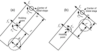
Fig. 7: Illustration of device inertia effects on the rendering of force/torque feedback around holding point
around the holding point will be naturally induced from the force/torque delivered to the center of the distal stage.
B. Device Inertia Effects on Force/torque Rendering
In any haptic simulations, we always hope that the requested force/torque can be faithfully transmitted to the user through the equipped joint motors. However, some factors which may affect this include motor dynamics, current amplifier charac-teristics, and arm structure [7]. Through experiments, we have found that the device inertia affects the perceived stiffness of the simulated objects non-uniformly. In this section, we discuss the inertia effects of the tip onto the rendering of the feedback. In Fig. 7a, a collision force f is acting on the stick. The equivalent wrench forFc at the center of the distal stage and the holding point is
Fc= [fc τc]T = [f l×f]T, (4)
Fh= [fh τh]T = [f h×f]T. (5)
Let us assume wrench Fc is faithfully rendered around the center of the distal stage. If the end effector is at rest or moving at constant velocity, the user will feel the desired
Fh. However, this is not a usual case, particularly during the contact transition period. If the user holds the stick and moves towards the ball with an incoming accelerationa, due to the inertia at the center of the distal stage, the actual force/torque generated at the user holding point is
Fh =fh τh T
=f−ma τc−(l−h)×(f−ma) T
=f−ma h×f+ (l−h)×ma T
(6)
Comparing (5) with (6), we can see that the translational force generated at the holding pointfh is smaller than the desired translational force fh by ma, while the torque generated
around the holding pointτh is larger than the desired torqueτh
by(l−h)×ma. This unbalance force/torque pair will generate a fast and large clockwise rotation around the holding point and give the user a perception of a stiffer virtual ball than it should be.
(a) (b)
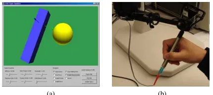
Fig. 8: (a)Stick-on-ball application GUI, and (b) Measuring primary holding pivot point with potentiometer
f at the center of the distal stage and the holding point are
Fc= [fc τc]T = [f l×f]T (7)
Fh= [fh τh]T = [f −h×f]T. (8)
But the actual induced force/torque around the holding point is
Fh =fh τh T
=f−ma τc−(l+h)×(f−ma) T
=f−ma −h×f+ (l+h)×ma T.
(9)
Comparing (8) and (9), we can see that the translational force generated at the holding point fh is still smaller than the desired translational force fh byma, but an additional term
(l+h)×mainτh counterbalances the desired torqueτ. If the incoming accelerationais large enough, the user will even feel a clockwise rotation around the holding point as opposed to the expected counterclockwise rotation. Therefore, in this case, it gives the user a perception of a softer virtual ball than it should be. It is interesting that the primary holding point also plays a role here. According to the factory specification sheet, the translational inertia of the Freedom6S hand controller at the center of the distal stage is around 250g and the rotational tensor is 0.17 gm2 for pitch and yaw, and 0.005 gm2 for roll. For an incoming acceleration of 1m/s2, the inertia may generate a 0.25N force which is definitely not negligible in haptic rendering. This problem also applies to other 6-DOF haptic interfaces.
C. Experiment Validation
To experimentally validate the effects of the device inertia, the example stick-on-ball application is chosen as a testbed. The experimental setup consists of a MPB Freedom6S hand controller interfaced with a PC running MS Windows XP. The PC is equipped with an Intel(R) Xeon 1700 MHz processor and 2 GB of RAM. A regular 19 inch flat CRT monitor is used for the graphic rendering without stereo support. Through the application’s user interface (UI) as shown in Fig. 8a, the user is able to modify the simulation’s parameters such as to manually set the holding point, and the stiffness of the virtual object, to enable/disable the real-time measurement of the primary holding point, etc.
To measure the user’s primary holding pivot point on the end effector, a membrane potentiometer is glued on the end effector, as shown in Fig. 8b. By pressing down on various parts of the potentiometer, its resistance changes linearly from 100 Ω to 10,000 Ω allowing us to accurately calculate the relative holding position on the strip which we use to estimate the holding pivot point. The activation force of the chosen potentiometer is 0.5-1.8N, so it can be easily actuated with human fingers without much distraction from the applica-tion itself. The holding point is visually displayed as three-orthogonal axes on the stick. With the visual display of the holding point inside the VE, the subject is able to know the relative position of the collision point and the primary holding point. A total of 5 subjects, with no known sensorimotor im-pairments with their hand or arm, took part in the experiments. Altogether, 6 levels of linear stiffness from 0.1N/mmto 0.6
N/mm at a spacing of 0.1 N/mm are randomly assigned to the virtual ball during the experiments for each subject. As described above, the maximum achievable linear stiffness without vibration depends on the position of the collision point. Vibrations can occur for this 6-level stiffness, particularly when the collision point is far from the center of the distal stage. To protect the motors, the subjects were asked to leave the collision state once they feel abnormal vibrations. For the experiment, each subject is asked to hold the end effector using the thumb and the index finger, forming a pinch grasp. For each stiffness level assigned, the subject is asked to touch the virtual ball with different parts of the stick by holding the end effector at different locations. The experimental results are consistent with the above mathematical analysis. All subjects report softer stiffness when touching the ball with the collision point in between the holding point and the center of the distal stage. There were no detected motor vibrations for collision points on the top half of the stick for all the 6 levels. When the collision point was on the other side of the primary holding point, all subjects reported that it felt stiffer. For assigned stiffness over 0.3 N/m, subjects felt vibrations when touching the ball with the lower part of the stick. It is possible that this stiffer stiffness sensation comes from these short duration vibrations. But the difference of the perceived stiffness is quite evident for all other cases. From the psychophysics point of view, studies in human stiffness perception show that the differential thresholds range from 8-22% [5] [12]. This is also to say that the inertia effects on the perceived stiffness cannot be ignored and needs compensation.
term −ma in the force component and the additional term
(l+h)×ma in the torque component. To compensate for the inertia in this case, we directly set the desired force/torque
Fh at the center of the distal stage and it gives fc =f and
τc =−h×f. With some algebra manipulations, the induced force/torque around the holding point now becomes
fh =f−ma
τh =−(2h+l)×f+ (h+l)×ma (10)
Referring to Fig. 7b, this is equivalent to moving the collision point away from the center of the distal stage by h. This movement of the contact force f helps to balance out the inertia effects. If the collision point is not between the center of the distal stage and the holding point, we do not modify force/torque Fc. Now in both cases, the user gets a stiffer
stiffness perception of the virtual object than it should normally be. Since the human stiffness perception JND is in the range of 8-22%, we expect that this artificial modification of the control force/torque will improve the uniform stiffness perception. The experimental results from 3 subjects show that the part where the users perceive a soft sensation due to the inertia indeed improved. One noticeable artifact is that there is a glitch due to the jump in the requested torque when the collision point is passing from one side of the holding point to the other.
In the second method, we will directly compensate for the inertia effects by estimating the acceleration of the control point. Referring to Fig. 7a, to transmit the desired force/torque
Fh given in (5) around the holding pivot point, the modified
Fc = [fc τc]with respect to the control point is given by
fc=fc+ma
τc=τc−l×ma.
(11)
It can be easily verified that (11) also applies to the situation described in Fig. 7b. However in this case, the estimation accuracy of the translational inertia on the end tip, the ro-tational inertia around the holding point, and the acceleration information becomes very important. Since the device is not equipped with an accelerometer, the acceleration information has to be derived from the position measurements. An adaptive 4-state Kalman filter to estimate the acceleration of the end effector was proposed in [13] considering the human arm/hand trajectory behavior. This is left as the future work.
V. CONCLUSION AND FUTURE WORK In this paper, we introduced the role of a user’s holding point in the current 6-DOF haptic rendering methods. We propose that the control point should be fixed for 6-DOF haptic rendering using direct rendering method. This ensures that regardless of how the tool is held by the user, correct and realistic force/torque feedback will be provided. However, this fixed control point does not directly work for the simulation based rendering method directly. We also briefly discussed the usefulness of the visual display of the primary holding point inside VE. We also studied the effects of the device inertia on the perception of stiffness properties assigned to virtual
objects. A stick-on-ball simulation is used for the experimental verification. Both theoretical analysis and experimental results show that the perceived stiffness is related to the location of the collision point, the primary holding point, and the center of the distal stage. Due to device inertia, distinct stiffness levels of the same virtual object are sensed when the user touches it using different part of the tool. We have instrumented the end effector of a haptic interface with a membrane potentiometer to measure the user’s primary holding point in real-time. Two methods are proposed for inertia compensation. The first method targets the perception of uniform stiffness of the virtual object. The experimental results show the effectiveness of the method. But when the collision point is passing from one side of the holding point to the other side, there is a clear glitch because of the non-continuity of the requested torque sent to the control point. In the second method, we directly target the compensation of the device inertia by estimating the acceleration of the control point and the inertia of the end effector in real-time. A more thorough investigation of this method is left for future work.
ACKNOWLEDGMENT
The authors would like to thank Dr. Ian Sinclair for his assistance with the MPB Freedom 6S hand controller.
REFERENCES
[1] M. A. Srinivasan and C. Basdogan, “Haptics in virtual environments: taxonomy, research status, and chanlleges,” Computers & Graphics, vol. 21, no. 4, pp. 393–404, 1997.
[2] D. D. Ruspini, K. Kolarov, and O. Khatib, “The haptic display of complex graphical environments,” inComputer Graphics Proceedings, SIGGRAPH, Aug. 1997.
[3] C. B. Zilles and J. K. Salisbury, “A constraint-based god-object method for haptic display,” inProc. of the International Conference on Intelligent Robots and Systems (IROS’95), vol. 3, 1995, p. 3146.
[4] M. C. L. and I. T,The grasping hand. Amsterdam: North-Holland, 1994.
[5] L. A. Jones and S. J. Lederman, Human Hand Function. Oxford University Press, Apr. 2006.
[6] B. T. Bethea, A. M. Okamura, M. Kitagawa, T. P. Fitton, S. M. Cattaneo, V. L. Gott, and D. D. Yuh, “Application of haptic feedback to robotic surgery,”Journal of Laparoendoscopic & Advanced Surgical Techniques, vol. 14, no. 3, pp. 191–195, 2004.
[7] J. P. Fiene, “Toward realistic haptic interactions with virtual rigid objects: Low-level dynamics and event-based algorithms,” Ph.D. dissertation, Stanford University, Dec. 2006.
[8] M. A. Otaduy and M. C. Lin,High Fidelity Haptic Rendering. Morgan
& Claypool Publishers, 2006.
[9] R. M. Murray, Z. Li, and S. S. Sastry,A Mathematical Introduction to Robotic Manipulation. CRC Press, INc., 1994.
[10] H. Z. Tan, B. Eberman, M. A. Srinivasan, and B. Cheng, “Human factors for the design of force-reflecting haptic interface,” inProceedings of the Third (3rd) International Symposium on Haptic Interfaces for Virtual Environment and Teleoperator Systems, ASME Dynamic Systems and Control Division, DSC-Vol. 55-1, Chicago, IL, 1994, pp. 353–359. [11] L. Jandura and M. A. Srinivasan, “Experiments on human performance
in torque discrimination and control,”Dynamic Systems and Control, vol. DSC-Vol. 55-1, pp. 369–375, 1994.
[12] L. A. Jones and I. W. Hunter, “A perceptual analysis of stiffness,”
Experimental Brain Research, vol. 79, no. 1, pp. 150–156, 1990. [13] J. Zhou, X. Shen, E. M. Petriu, and N. D. Georganas, “Linear velocity