III
R
S
I
D A
D
· C
A RL O S I II ·
DE
M A D
UNIVERSITY CARLOS III OF MADRID
Department of Telematics Engineering
Master of Science Thesis
Client-based and Network-based
solutions for
Distributed Mobility Management
Author: Fabio Giust
Supervisor: Prof. Carlos Jes ´us Bernardos Cano
Internet traffic has increased steeply in recent years, mainly due to the fruition of video and other streaming contents, social platforms and peer-to-peer networks. In addition, the quick penetration of hand-held devices equipped with multiple radios (e.g., 3G and WiFi), sees to it that wireless access represents an ever-growing portion of current and future de-mand, thus encouraging operators to investigate and deploy different combinations of wire-less access technologies with the purpose of reducing their operational costs (the so-called “4G” architecture).
It is hence necessary to adopt an efficient mobility management technique to meet users’ expectation of an “anywhere, anytime” connectivity. Nevertheless, the use of centralized mobility management approaches – such as Mobile IPv6 and Proxy Mobile IPv6 – is fore-seen to bring some difficulties to operators, due to the expected large number of mobile users and their exigent demands.
All this has triggered the need for Distributed Mobility Management (DMM) alterna-tives, focused on moving the mobility anchors from the core network to the edge, pushing them closer to the users. The purpose of such new research direction is to overcome the limitations imposed by a centralized approach, alleviating operators’ costs by deploying a more efficient network, envisioning also the heterogeneity of the underlying technology.
This work first explores two protocols for mobility support, Mobile IPv6 and Proxy Mobile IPv6, taken as main referents for, respectively, the host-based mobility approach and the network based one. We next elaborate the extensions and the changes to transform them according to the distributed mobility management paradigm, proposing several complete solutions. Finally, we analytically compare the distributed solutions to their centralized counterparts, in order to derive which are the most suitable scenarios for their applicability.
3GPP 3rd Generation Partnership Project
AP Access Point
AAA Authentication, Authorization and Accounting
BA Binding Acknowledgment
BC Binding Cache
BCE Binding Cache Entry
BU Binding Update
CGA Cryptographically Generated Address
CMD Central Mobility Database
CN Correspondent Node
CoA Care-of Address
CoT Care-of Test
CoTI Care-of Test Initialization
DAD Duplicate Address Detection
DAR Distributed Anchor Router
DL Downlink
DMM Distributed Mobility Management
DSMIPv6 Dual-Stack Mobile IPv6
FAMA Flat Access and Mobility Architecture
GTP GPRS Tunnelling Protocol
HA Home Agent
HMIPv6 Hierarchical Mobile IPv6
HNP Home Network Prefix
HoA Home Address
IEEE The Institute of Electrical and Electronics Engineers
IETF The Internet Engineering Task Force
LMA Local Mobility Anchor
LMD Localized Mobility Domain
MAAR Mobility Anchor and Access Router
MAG Mobile Access Gateway
MH Mobility Header
MIHF Media Independent Handover Functions
MIIS Media Independent Information Service
MIPv4 Mobile IPv4
MIPv6 Mobile IPv6
MN Mobile Node
MN-ID Mobile Node Identifier
ND Neighbor Discovery
PBA Proxy Binding Acknowledgment
PBU Proxy Binding Update
P-CoA Proxy Care-of Address
PMIPv6 Proxy Mobile IPv6
PoA Point of Attachment
PoS Point of Service
RA Router Advertisement
RO Route Optimization
RR Return Routability
RS Router Solicitation
RTT Round Trip Time
SLAAC StateLess Address Auto-Configuration
1 Introduction 1
2 Centralized vs. Distributed Mobility Management 3
2.1 Mobile IPv6 . . . 3
2.1.1 Entities . . . 4
2.1.2 Protocol Overview . . . 4
2.1.3 Security . . . 5
2.2 Proxy Mobile IPv6 overview . . . 6
2.2.1 Entities . . . 7
2.2.2 Operations . . . 8
2.2.3 Security . . . 9
2.3 Limitations of centralized mobility management solutions. . . 9
2.4 State of the Art . . . 10
3 Client-based solution for DMM: FAMA 12 3.1 Working scheme . . . 12
3.2 Security . . . 13
4 Network-based solutions for DMM 16 4.1 Fully distributed approach . . . 17
4.1.1 Full distribtion with IEEE 802.21 . . . 19
4.2 Partially distributed approach . . . 20
4.2.1 The CMD is a PBU/PBA relay . . . 22
4.2.2 The CMD as MAAR locator . . . 23
4.2.3 The CMD as PBU/PBA proxy . . . 23
5 Evaluation of the DMM solutions 26 5.1 Overhead Analysis . . . 26
5.1.1 Client-based scenario . . . 26
5.1.2 Network-based scenario . . . 27
5.2 Handover latency . . . 28
5.3 Communication delay . . . 30
5.4 Final remarks . . . 32
6 Conclusions 33
2.1 Mobile IPv6 overview. . . 5
2.2 Proxy Mobile IPv6 overview . . . 7
2.3 Registration to a Proxy Mobile IPv6 domain . . . 8
3.1 FAMA architecture and example scenarios . . . 13
3.2 Signaling between the mobile node and the Distribute Access Router . . . . 15
4.1 Fully distributed PMIPv6 . . . 17
4.2 Fully distributed approach with IEEE 802.21 . . . 19
4.3 Partially distributed PMIPv6: initial registration . . . 21
4.4 Partially distributed PMIPv6: CMD as message relay . . . 22
4.5 Partially distributed PMIPv6: data flow . . . 23
4.6 Partially distributed PMIPv6: CMD as MAAR locator. . . 24
4.7 Partially distributed PMIPv6: CMD as message proxy. . . 25
5.1 Edge network divided in IP access cells . . . 32
Introduction
The increasing demand of mobile data services from users is no longer a threat to oper-ators, but a reality that needs to be tackled. We are witnessing that the number of wireless mobile subscribers accessing data services does not stop increasing. This is motivated by a variety of different reasons: 3G and WLAN accesses are widely available (combined, cov-erage reaches almost 100% of dense populated areas in developed countries) and affordable by users (most mobile handsets are 3G and WLAN capable, all laptops and netbooks are equipped with WLAN interfaces, 3G USB modems are quite cheap and operators offer flat rates to their customers). Besides, the number and popularity of applications designed for smart-phones that make use of Internet connectivity is getting larger every day, contribut-ing to an increase of market penetration of such devices (e.g., iPhone, Android, Blackberry and Windows Mobile phones), which results in growing demands for Internet connectivity everywhere.
Additionally, operators are migrating their networks to full IP based networks, as the
most recent mobile architectures like the IEEE 802.16 suite (also known as WiMAX)1and
the 3GPP Evolved Packet System (EPS)2, for both voice and data, triggering a real need
for IP mobility management solutions, which up to now had shown little or no deployment penetration, being proprietary customized solutions used instead.
Most of the currently IP mobility solutions standardized by the IETF3, like Mobile IPv6
(MIPv6) [19], or Proxy Mobile IPv6 (PMIPv6) [17] rely to a certain extent on a central-ized mobility anchor entity. This centralcentral-ized network node is in charge of i) the control of the network entities involved in the mobility management (i.e., it is a central point for the control signaling), and ii) the user data forwarding (i.e., it is also a central point for the user plane). This makes centralized mobility solutions prone to several problems and limita-tions, as identified in [8]: longer (sub-optimal) routing paths, scalability problems, signaling overhead (and most likely a longer associated handover latencies), more complex network deployment, higher vulnerability due to the existence of a potential single point of failure, and lack of granularity on the mobility management service (i.e., mobility is offered on a per-node basis, not being possible to define finer granularity policies, as for example on a
1
The Working Group’s official webpage can be found athttp://grouper.ieee.org/groups/802/ 16/
2
3rd Generation Partnership Project,http://www.3gpp.org/ 3
Internet Engineering Task Force,www.ietf.org
per-application basis).
Because of all the aforementioned issues, big operators are now looking for alternative mobility solutions that are more distributed in nature, allowing a cheaper and more efficient network deployment capable to meet their customers’ requirements. In particular, there is an effort in the IETF, called Distributed Mobility Management (DMM), that is currently addressing exactly this particular problem, first starting from a clear definition of the problem statement [8].
There are basically two main approaches being researched now: one aimed at making Mobile IPv6 work in a distributed way, and another one doing the same exercise for Proxy Mobile IPv6. In this work, we explored both approaches producing DMM designs starting from the corresponding IETF protocols and stretching them to work in a distributed way: our objective was to not introduce any new message nor data structure, but to use, instead, what is already standardized, applying the necessary changes in terms small extensions to legacy message formats and, especially, re-ordering nodes’ operations, altering their state-machine. Hence, we present a complete solution for a mobility client inspired by MIPv6, called “Flat Access and Mobility Architecture” (FAMA) and, besides, we show several proposals for network-based DMM, divided into two categories, the fully distributed approach and the partially distributed one.
The rest of the thesis is organized as follows.
• Chapter2summarizes how centralized mobility management works, by describing the
operations of Mobile IPv6 and Proxy Mobile IPv6, and highlights the main limitations of this kind of approach, providing some state-of-art DMM schemes, referencing the main output available in literature and in the IETF.
• Chapter3presents Flat Access and Mobility Architecture (FAMA), a complete
solu-tion for client-mobility based on Mobile IPv6, implementing an alternative security mechanism.
• Chapter 4 introduces partially and fully distributed approaches for network-based
DMM, based on Proxy Mobile IPv6, showing several solutions for both approaches.
• Chapter5analyzes and compares our solutions with their centralized counterparts in
terms of overhead, handover latency and communication delay.
• Chapter6concludes the thesis, highlighting the main results and proposing the
Centralized vs. Distributed Mobility
Management
The mobility management schemes standardized by the IETF for IPv6 networks are ex-tensions or modifications of the well known Mobile IPv6 protocol (MIPv6) [19], such as Proxy Mobile IPv6, (PMIPv6) [17], Dual-Stack Mobile IPv6 (DSMIPv6) [35] and Hierar-chical Mobile IPv6 (HMIPv6) [36]. However, they come at the cost of handling operations at a cardinal point, the mobility anchor, and burdening it with data forwarding and control mechanisms for a great amount of users. This node is usually far away from the edge, deep into the core network, and, although HMIPv6 proposes to split the management hierarchi-cally, this only shifts the problem close to the edge without really addressing the flat IP architecture demand.
Next sections present the two protocols chosen as most relevant examples for the client-based mobility support and the network client-based one, respectively MIPv6 and PMIPv6. Fi-nally, we highlight the limitations of such approaches, hence the motivations that push for distributed mobility management and some works proposed in literature dealing with DMM.
2.1
Mobile IPv6
A step forward in the design of an efficient mobility protocol was achieved in 2004 with the release of RFC 3775 [19] by David Johnson, Charlie Perkins and Jari Arkko, named
Mobility Support in IPv61, or simply MIPv6. Mobile IPv6 inherits most of the mechanisms
introduced with its predecessor, Mobile IPv4 (MIPv4) [32], but, also, it brings several en-hancements due to the wise exploitation of IPv6 features.
Next subsections detail the involved entities and the protocol operations. Note that most of the terms introduced in the following paragraphs are common to more mobility protocols, and thus are used throughout the document with that same meaning, except when stated otherwise.
1
At the time of writing this report, RFC 6275 is being released that obsoletes the mentioned one. However, the new release is simply an update of the old one, and it does not introduce relevant changes for the purposes of the work
2.1.1 Entities
Here is the list of nodes comprised in the MIPv6 architecture.
• Mobile Node (MN). It is the moving host, usually referred as a terminal that changes
point of attachment; the notation of Mobile Terminal (MT) is also used in literature2.
The Mobile Node (MN) can configure two types of addresses:
– Home Address (HoA). It is the permanent and globally reachable IP address configured by the MN when at home. The Home Network is thus defined as the network where the HoA is topologically valid.
– Care-of Address (CoA). It is the temporary IP address configured by the MN to maintain connectivity when in a foreign network.
• Home Agent (HA). This node is in charge of storing an association between the HoA
and CoA (a binding) per each MN. If the MN is present in the Home Network, the HA is not necessarily involved in the packets delivery to the MN, otherwise, if the MN registered a CoA at the HA, it intercepts the packets destined to the HoA, and it encapsulates them to the CoA to properly route them to the final recipient. This procedure is known also as IP tunneling [31].
• Correspondent Node (CN). It is the other endpoint of a communication with the MN.
It can be a fixed or moving node.
2.1.2 Protocol Overview
In MIPv6, the HA is an entity located in the home network which enables global reach-ability and session continuity for the mobile nodes associated to it. The HA anchors the permanent IP address used by the MN, the (HoA), and defends the HoA’s reachability when the MN is not at home, by intercepting the traffic addressed to the HoA and redirecting it to the MN’s current location.
When away from its home network, the MN acquires a temporal IP address from the visited network – the (CoA) – and informs the HA about its current location by sending a Binding Update (BU) message. The HA, in turn, updates the session information related to the MN stored in a database, called Binding Cache (BC), and sends back the response in a Binding Acknowledgment (BA) message. A bidirectional IP tunnel is established between the two nodes and the data traffic is transmitted through it. The necessity for data packets to traverse the HA lays down a suboptimal path between MN and CN called angular routing, thus an additional operation has been defined to overcome this limitation. Route Optimiza-tion (RO) is the procedure standardized to register the MN’s CoA at the CN as well, so that the communication can be moved (i.e., packets are forwarded) through a shorter path to destination. Unfortunately, in order to perform RO, the CN needs to be provided with the MIPv6 module in its TCP/IP stack implementation, otherwise the control messages cannot
2
Figure 2.1: Mobile IPv6 overview
be processed correctly. Usually, the devices available in the market implement the IPv6 stack without the mobility component. The fact that both MN and CN need to run an extra module in addition to the IPv6 stack is one of the reasons that led to the development of network
based mobility solutions (see Section2.2).
The working scheme of Mobile IPv6 mostly reflects that for IPv4, with minor variations due to the flexibility gained with IPv6 properties. For instance, when a MN is away, it can configure its address in the foreign network using standard Neighbor Discovery (ND) operations and StateLess Address Auto-Configuration (SLAAC) [28]. Hence, there is no need for a foreign agent to take part of the procedure, also for the subsequent signaling. Besides, BU/BA messages are built in a modular way, appending the so-called Mobility Header (MH) to an IPv6 header, and with some additional options as trailers to this new message header.
2.1.3 Security
The security mechanisms adopted in MIPv6 leverage the IPsec suite [1,12] in Encrypted
Security Payload mode [21, 26]. This work does not explore in depth the security issues,
thus the scope is limited to present at a very high level the security principles adopted in the
protocols, while further details can be found in the cited references and in [19,29].
is known as redirection attack. A bogus node registers his address as CoA for a HoA that belongs to another MN. If the attempt is successful, the attacker is able to steal traffic from other users. Conversely, the misbehaving node registers its HoA with a third party’s CoA and starts several IP sessions with the purpose of flooding the victim’s links and/or draining its resources. For this reason, the the IPsec suite is used in MIPv6 to authorize an MN and to authenticate its control communication.
However, such kind of protection cannot be guaranteed for the RO procedure, as no secure associations take place with the CN, which is then particularly prone to redirection attacks. After the RO procedure, a CN basically stores a binding between the MN’s HoA and CoA as an HA does, but BU and BA are secured whilst RO messages are not. Hence, a CN must make sure that:
• the MN is really identified by the HoA it claims;
• it is actually reachable at the CoA.
The security mechanism designed for this scope is called Return Routability (RR), and, for the sake of simplicity, all the details are skipped to highlight the elegance of the basic idea. The MN starts the procedure sending a request through both paths to the CN, i.e., the direct one and that via the HA. The CN replies transmitting two tokens through the distinct paths, i.e., one with destination the HoA and the other with destination the CoA. The two tokens are necessary to generate a key used to encrypt the subsequent registration message (a BU) sent by the MN to the CN. If the key is correct, i.e., if the CN is able to decrypt the message, then it means that the MN has successfully received both tokens, hence it is the legitimate owner of the HoA and it is actually located at the CoA claimed. Hence a BA is sent back to conclude the procedure and enable the optimized path.
2.2
Proxy Mobile IPv6 overview
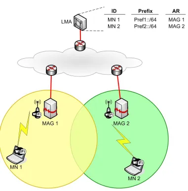
A new concept for mobility management emerged with the network-based approach, for which mobility support is provided to hosts in movement without their involvement, as long as they are roaming inside a Localized Mobility Domain (LMD). The efforts towards this direction resulted in 2007 with the standardization of Proxy Mobile IPv6, (PMIPv6) [17], developed as an enhancement of MIPv6. In PMIPv6, the home agent is replaced by the Local Mobility Anchor (LMA): it is in charge of routing packets in uplink and downlink containing the IPv6 prefixes assigned uniquely to MNs on a per user basis, the Home Network Prefix (HNP), and it stores the MNs’ mobility sessions information.
Figure 2.2: Proxy Mobile IPv6 overview
2.2.1 Entities
The core functional entities in the PMIPv6 infrastructure are (see Fig.2.2):
• Mobile Node (MN). It is the moving host.
• Mobile Access Gateway (MAG). This entity performs the mobility related signalling
on behalf of an MN that it is attached to one of its access links. The MAG is usually the access router for the MN, i.e., the first hop router and default gateway in the lo-calized mobility management infrastructure. It is responsible for tracking the MN’s movements on the access network. There are multiple MAGs in an LMD.
• Local Mobility Anchor (LMA). This is an entity within the backbone network that
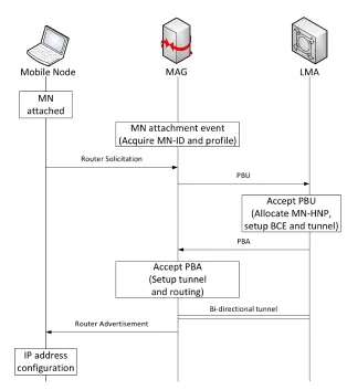
Figure 2.3: Registration to a Proxy Mobile IPv6 domain
from the MN through tunnels between the LMA and the corresponding MAG. The LMA is also responsible for assigning IPv6 prefixes to MNs (e.g., it is the topological anchor point for the prefixes assigned to the MN). There may be more than one LMA in an LMD.
2.2.2 Operations
The sequence of operations in PMIPv6 is quite similar to that drawn in MIPv6, except that those actions performed by the MN in MIPv6 are now responsibility of the MAG.
from the LMA (the Proxy Care-of Address (P-CoA)). Then, the LMA establishes on its side a bi-directional tunnel to the MAG for the MN’s traffic forwarding, and it replies to the MAG with a Proxy Binding Acknowledgment (PBA) message, including the prefix assigned to the MN. Once the PBU/PBA handshake is over, the MAG configure the P-CoA as the second end-point of the tunnel with the LMA, and unicasts a Router Advertisement (RA) message to the MN specifying the prefix to be used for the IP connectivity. Now the MN is able to configure one or more addresses from the assigned prefix and the registration procedure is
over (see Figure2.3). Whenever the MN moves, the new MAG updates the MN’s location
in the LMA by means of a PBU/PBA handshake, and advertises through a unicast RA the same prefix to the MN. The new MAG shows the same layer-2 and layer-3 identifiers to the MN, thereby making the IP mobility transparent to the MN. Thus, the MN always keeps the address configured when it first entered the LMD, even after changing its point of attachment to the network.
2.2.3 Security
The security mechanisms in PMIPv6 are split into two levels related to i) the accounting of an MN and ii) the authentication of control messages. Indeed, whilst in MIPv6 the secure association between MN and HA converges the procedures into one, as the sender of control messages is the HA or the MN itself, in PMIPv6 the MN is first authenticated and authorized for the service by the MAG, and, next, mobility messages are authenticated between MAG and LMA.
Upon a MN’s attachment to the network, either an authentication mechanism is deployed on the access link, or the MAG performs an Authentication, Authorization and Accounting (AAA) check querying a dedicated infrastructure. RFC 5213 recommends the use of Ra-dius [33] or Diameter [7] for this purpose. In both cases, the MN results to be authorized for the PMIPv6 service and provided with an unique identifier in the domain – the MN-ID. Moreover, the messages between MAG and LMA are secured with IPsec in a similar way as
in MIPv6 (see Section2.1.3).
2.3
Limitations of centralized mobility management solutions
Centralized mobility solutions, such as those described previously, base their operation on the existence of a central entity that anchors the IP address used by the mobile node (e.g., the HA and the LMA). This central anchor point is in charge of tracking the location of the mobile and redirecting its traffic towards its current topological location. While this way of addressing mobility management has been fully developed by the Mobile IP protocol family and its many extensions, there are also several limitations that have been identified [8]:
• Sub-optimal routing. Traffic always traverses the HA/LMA, which leads to paths
located at the very edge of the network, close to the user terminal, data paths tend to be shorter.
• Scalability problems. With current mobility architectures, networks have to be
di-mensioned to support all the traffic traversing the central anchors. This poses several scalability and network design problems, as the central mobility anchors need to have enough processing and routing capabilities to be able to deal with all the mobile users’ traffic simultaneously. Besides, the operator’s network also needs to be dimensioned to be able to cope with all the users’ traffic. A distributed approach is inherently more scalable, as the mobility management tasks are distributed and shared among several network entities, which therefore do not need to be as powerful as the centralized alternative.
• Reliability. Centralized solutions share the problem of being more prone to reliability
problems, as the central entity is a potential single point of failure.
• Lack of fine granularity on the mobility management service. With current
central-ized mobility management solutions, mobility support is offered at a user granularity. This means that the network can just decide if mobility is provided or not to the user, but cannot offer a finer granularity, for example, to allow part of his/her traffic not to be handled by the mobility solution. There are many scenarios in which part or all the traffic of a user does not really need to be mobility enabled, as for example when the user is not mobile (at least during the lifetime of the communication) or the applica-tion itself is able to effectively deal with the change of IP address caused by the user movement. In all these situations, it would be more efficient not to enable mobility.
• Signaling overhead. This is related to the previous limitation. Any mobility
man-agement solution involves certain amount of signaling load. By allowing mobility management to be dynamically enabled and disabled on a per application basis, some signaling can be saved, as well as the associated handover latency. Of course, this depends on the particular scenario, as the use of distributed mobility architectures can also lead to a higher signaling load in case of very dynamic scenarios in which all the traffic is required to be mobility enabled.
2.4
State of the Art
The mobility management of users in operator networks has seen in recent times the release of several IPv6 centralized solutions to tackle the issue of continuously providing access and mobility support, as those mentioned in the introduction of this thesis.
One of the efforts mentioned by [23] is Flat Access and Mobility Architecture (FAMA) [15], our contribution for host-based DMM, described in detail in next chapter. Another proposal is Dynamic Mobile IP (DMI) [20], with the particularity of keeping active and reachable old MN’s addresses (i.e., CoAs) as long as there is a session bound to one of those. Basically it suggests, when the MN is not at home, to start communications with the CoA, so that traversing the HA is avoided for new traffic. However, the draft is not taking into consideration placing the mobility anchors at the MNs’ access routers.
The network-based proposals that are subject of this thesis are also covered in papers and draft submitted by the author himself to international conferences and the IETF community,
see [14,16,4].
However, other descriptions exist on how to have a PMIPv6-like distributed scheme. In [9], a Proxy Mobile IPv6 domain is envisioned to cover a small area, so that the LMA can be deployed closer to the MAGs, and thus to the users. In this way, many little PMIPv6 domains form a bigger super-domain, and a custom LMA-to-LMA interface is necessary to exchange the control signaling to handle the MN moving from a domain to another. The draft provides also a solution to achieve route optimization in several scenarios, at the cost of an excessive control messages exchange. Also, the architecture deployment requires a big effort, since every small domain is made of the complete Proxy Mobile IPv6 equipment (LMA + MAGs).
Some other projects of distributed architectures inspired by PMIPv6 are Dynamic Mobil-ity Anchoring (DMA) [34] and Dynamic Distributed MobilMobil-ity Management (DDMM) [5]. According to these documents, mobility support is provided on demand, that is, only for those MNs that change access point with ongoing connections. The MN configures and maintains an IP address for each access network it visits, and the access router in that access network is the anchor for the communications established using the IP address assigned by the router. This means that an access router acts as a standard router when the MN is at-tached to it, otherwise it tunnels the packets to the access router where the MN is currently
attached. Even if the ideas in those papers are similar to what are presented in Chapter4,
in [34] it is not detailed how to build the control signaling, while in [5] a technology-agnostic implementation is used with a more passive approach, greatly reducing signaling on the in-frastructure network. It relies on the MN to constantly keep sending packets in order for the network to passively learn where it is located and adequately setup tunnels and routing
(this concept is covered again in Section 4.1). In [6] a simulation environment is used to
compare behaviors between DMA and MIPv6, proving that although DMA greatly reduces the handover duration, it has an increased end-to-end delay.
Client-based solution for DMM:
FAMA
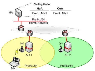
Distributed Mobility Management approaches try to overcome the limitations of the tra-ditional centralized mobility management, by bringing the mobility anchor closer to the MN. Following this idea, in our proposal, called Flat Access and Mobility Architecture (FAMA), the MIPv6 centralized home agent is moved to the edge of the network, being deployed in the default gateway of the mobile node. That is, the first elements that provide IP connectiv-ity to a set of MNs are also the mobilconnectiv-ity managers for those MNs. In the following we will call these access routers Distributed Anchor Router (DAR).
3.1
Working scheme
Every time a mobile node attaches to a DAR, it gets an IPv6 address which is topo-logically anchored at the DAR. That means that while attached to this DAR, the mobile can send and receive traffic using that address without any tunneling nor special packet handling. Every time the mobile node moves to a different DAR, it gets a new IPv6 address from the new access router. In case the MN wants to keep the reachability of the IPv6 address(es) it obtained from the previous DAR (note that this decision is dynamic and can be done on an application basis for example), the mobile has to involve its MIPv6 stack, by sending a Binding Update to the DAR where the IPv6 address is anchored, using the address obtained from the current DAR as care-of-address. In this way, the IPv6 address that the node wants to maintain plays the role of home address, and the DAR from where that address was config-ured plays the role of home agent (for that particular address). Note that FAMA architecture basically enables a mobile node to simultaneously handle several IPv6 addresses – each of them anchored at a different DAR – ensuring their continuous reachability by using Mobile IPv6 in a distributed fashion (i.e., each access router is a potential home agent for the address it delegates, if required). This distributed address anchoring is enabled on demand and on a per-address granularity, which means that depending on the user needs, it might be the case that all, some or none of the IPv6 addresses that a mobile node configures while moving within a FAMA domain, are kept reachable and used by the mobile.
Figure 3.1: FAMA architecture and example scenarios
3.2
Security
In traditional Mobile IPv6, the communication between the MN and the HA is secured through IPsec [12]. Following a similar approach in FAMA is difficult due to the large num-ber of security associations that would be required, since any gateway of the access network can play the role as home agent for any mobile node. In order to overcome this problem and provide authentication between the DAR and the MNs, we propose the use of Cryptograph-ically Generated Address (CGA) [2], as introduced in [24]. CryptographCryptograph-ically Generated Addresses are basically IPv6 addresses for which the interface identifier is generated by
computing a cryptographic one-way hash function from a public key and the IPv6 prefix1.
The binding between the public key and the address can be verified by re-computing the hash
1There are additional parameters that are also used to build a CGA, in order to enhance privacy, recover from
function and comparing the result with the interface identifier. To authenticate a message, the packet is signed with the corresponding private key, hence the receiver is able to authenti-cate the message with the knowledge of the address and the public key. CGAs are a powerful mechanism allowing packet authentication without requiring any public-key infrastructure, and hence it is well-suited for this application.
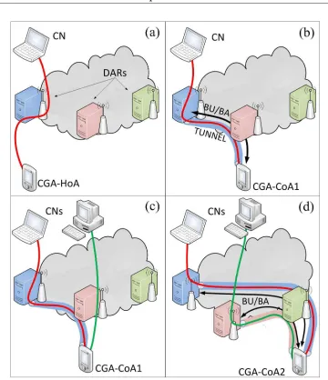
Following the ideas presented above, every time an MN attaches to a DAR, it configures a CGA from a prefix anchored at the DAR (e.g., by using stateless address auto-configuration mechanisms). This address can then be used by the MN to establish a communication with a
remote Correspondent Node (CN) – see Fig.3.1-(a) – while attached to that particular DAR.
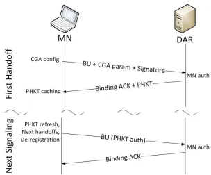
If the mobile then moves to a new DAR (nDAR), the following two cases are possible: i) there is no need for the address that was configured at the previous DAR (pDAR) to survive the movement: in this case there is no further action required; ii) the mobile wants to keep the reachability of the address configured at pDAR: in this case Mobile IPv6 is triggered, and the MN sends a Binding Update message to the pDAR, using the address configured at the previous DAR as home address, and the address configured at the new DAR as care-of address. This BU includes the CGA parameters and signature, which are used by the receiving DAR to identify the MN as the legitimate owner of the address. Although the use of CGAs does not impose a heavy burden in terms of performance, depending on the number of MNs handled by the DAR, the processing of the CGAs can be problematic. To reduce the complexity of the proposed solution, we suggest an alternative mechanism to authenticate any subsequent signaling packets exchanged between the MN and the DAR (in case the mobile performs a new attachment to a different DAR). This alternative method relies on the use of a Permanent Home Keygen Token (PHKT), which will be used to generate the Authorization option that the MN has to include in all next Binding Update messages. This token is forwarded to the MN in the Binding Acknowledgment message, sent in reply to the
BU. The procedure is depicted in Fig. 3.2. Once the signaling procedure is completed, a
bi-directional tunnel is established between the mobile node and the DAR where the IPv6 address is anchored (the “home” DAR – HDAR – for that particular address), so the mobile
can continue using the IPv6 address, as shown in Fig.3.1-(b).
In case the MN performs any subsequent movements and it requires to maintain the reachability of an address for which it has already sent a BU, the following BU messages can be secured using the PHKT exchanged before, reducing the computational load at the receiving DAR.
Figure 3.2: Signaling between the mobile node and the Distribute Access Router
knowledge of both tokens is a proof that the MN is the legitimate node who has sent the BU and also is reachable at the CoA indicated. As all security improvements, the one proposed incurs in a performance penalty, in this case an increase in the handover delay. Specifically this enhanced security approach requires four messages to be exchanged between the MN and the DAR instead of the two messages of the original solution. In terms of handover delay, it increases it by a factor of two, as the new solution requires two Round Trip Times (RTT) to conclude, instead of one.
Note that on every attachment of a node to a DAR, the terminal also obtains a new IPv6 address which is topologically anchored at that DAR, and that this address can be used for new communications (avoiding in this way the tunneling required when using an address
anchored at a different DAR), as shown in Fig.3.1-(c). A mobile can keep multiple IPv6
addresses active and reachable at a given time, and that requires to send – every time the MN moves – a BU message to all the previous DARs that are anchoring the IP flows that the MN
wish to maintain. For instance, in the example depicted in Fig.3.1-(d), the MN sends a BU
Network-based solutions for DMM
The IETF has been working on an analysis document [38] that proposes the guidelines for the development of network-based distributed mobility management solutions, that can be divided into two main categories:
• Partially distributed, that basically consists on removing the data path constraint
towards the anchor, but maintaining a centralized control plane;
• Fully distributed, that consists on eliminating any centralized role in the architecture.
In next sections we address how to develop DMM designs based on PMIPv6 for both ap-proaches, describing in the detail the required procedures. Nevertheless, all solutions share the same data forwarding plane, briefly summarized here: a MAG – that we call Mobility Anchor and Access Router (MAAR) – assigns IPv6 prefixes on a per-MN basis from a prefix pool that belongs to that MAAR only and that are anchored to it (i.e., topologically correct in its access subnet only). In this way, an MN receives a prefix, and therefore con-figures an IP address, per each visited MAAR. A MAAR anchors the flows started using the prefixes it advertises: it acts as plain IPv6 router (i.e., it does not encapsulate packets) when the MN is still attached to its network, otherwise, it establishes a tunnel with the MAAR currently serving the MN.
We introduce next the terminology related to the roles that the MAAR may play for each IP flow traversing it:
• Anchor MAAR (A-MAAR) is referred to the MAAR that advertised the prefix used
in the communication/flow.
• Serving MAAR (S-MAAR) is referred to the MAAR where the MN involved in the
communication/flow is attached to.
It should be noted that this separation is only conceptual and applied on a flow basis: the same MAAR can play simultaneously different roles for the different flows. With respect to the PMIPv6 semantic, an A-MAAR acts as an LMA, and the S-MAAR as a MAG.
4.1
Fully distributed approach
In the fully distributed approach, the LMA and the MAG are collapsed into the MAAR. In other words, MAARs are not only responsible of the forwarding of flows established with their prefixes in the manner described before, but they also maintain and handle the mobility sessions for those flows. The next use case example clarifies the working scheme of the proposed design.
(a) Initial registration (b) Handover signaling and registration in previous MAARs
(c) Start of a new flow (d) Handover with two flows
Figure 4.1: Fully distributed PMIPv6
remote correspondent node, see Fig.4.1(a).
When a handover occurs, MAAR2learns that the MN has attached and advertises a new
prefix, Pref2. Then, it sends a PBU message to MAAR1, that is anchoring ongoing MN’s
flows, and, upon the corresponding PBA reception, a tunnel is established among them,
hence the flows can be redirected through it, as shown in Fig.4.1(b). It is worth noticing that,
in this juncture, MAAR1is the A-MAAR for the flow, while the S-MAAR is represented by
MAAR2; in addition, MAAR2 becomes the A-MAAR and S-MAAR for the flows started
by the MN using the new address (see Fig.4.1(c)). Moreover, upon a new movement of the
MN to a new access network, MAAR3assigns a third prefix and updates the MN’s location
to all its former S-MAARs, i.e. MAAR1 and MAAR2, by means of PBU messages. Again,
when the PBAs are received, tunnels are set up and the old communications are recovered,
as depicted in Fig.4.1(d).
The main issue in this mechanism is how a MAAR can differentiate between the first attachment to the network and subsequent handovers, that is, the MAAR, upon the MN’s attachment, should be informed of the past MN’s location to be able to contact, if neces-sary, the formerly visited MAARs. More than one solution is suggested here, each with advantages and disadvantages that should be evaluated looking for the best trade-off:
• Broadcast PBU. When a MAAR detects the attachment, it sends a broadcast request
to all the MAARs and waits for a reply, that might be a void PBA in case the MN joined the network for the first time. It should be noted that sending the messages only to the neighbor MAARs is not enough to reconstruct the MN’s past history, thus the procedure might result excessively long and introduces unnecessary signaling.
• Terminal indication. The MN explicitly sends the prefixes acquired previously when
joins the new access network (e.g., as options in the Router Solicitation message). Although this is a fast and light procedure, it requires some capabilities on the host that are not always possible to rely on (or not even desirable), and might pose some security issues if a malicious MN misbehaves.
• Automatic learning. In [5] it is proposed that mobility capable access routers learn
the previous MN’s location by inspecting the source address of packets sent by the MNs. That is, these routers store in an internal database the prefix pools belonging to the others, and, upon receiving the first uplink packet sent by the MN after a move-ment, they check which is the access router the prefix belongs to and establish a tunnel with it. This requires little signaling but it may lead to an excessive delay if the MN does not send anything and the router has to explicitly request a packet.
• Layer-2 handover support. Handover may follow a Make-Before-Break
philoso-phy and integrate layer-2 and layer-3 mobility procedures within the same framework to assist and drive the handover. IEEE 802.21, Media Independent Handover Ser-vices [25], is a suitable protocol for this purpose.
addition, the IEEE 802.21 suite is intended to allow inter-technology handovers, giving sup-port to MNs roaming within a heterogeneous environment with multiple radio access tech-nologies. Next paragraphs are devoted to detail this approach.
4.1.1 Full distribtion with IEEE 802.21
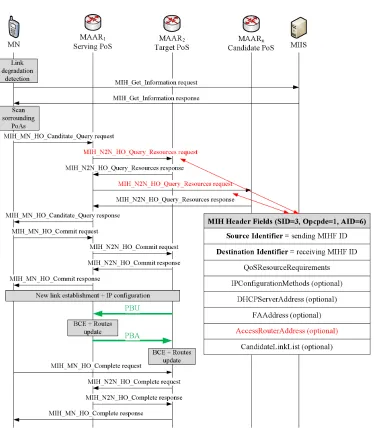
Figure 4.2: Fully distributed approach with IEEE 802.21: message exchange sequence dur-ing handover
can directly exchange messages with a peer MIHF installed in the terminal. A PoS instance serves one terminal, so multiple instances run in the same network entity that handles the MNs in its access network. In our design, PoSs are implemented in the MAARs. PoSs maintain information about the layer-2 access entities as Base Stations, Access Points and similar nodes connected to the MAAR, by interacting with the MIHF operating in them. These MIHF are called Point of Attachments (PoAs), and provide the access link to MNs, but they do not establish a direct control communication with the MIHF in the terminals.
In Figure4.2MAARs and PoSs are represented in the same entities, whilst PoAs are
omit-ted to keep the chart simple. Indeed, the picture highlights the message exchange between the MN and the MAAR, and among MAARs, rather than the complete procedure specified by the IEEE 802.21 standard. According to IEEE 802.21 working scheme, a PoS learns when a handover for its MN is imminent (the details of how this is done are out of scope in this thesis); therefore it queries resources availability in the surrounding PoAs that are not
under its direct control, by means of a message calledMIH N2N HO Query Resources
request(highlighted in red in Figure4.2), sent to the corresponding PoSs connected to the desired PoAs (the latter are discovered by the MN, or by the network, after an informa-tion retrieval procedure involving the Media Independent Informainforma-tion Service – MIIS –, and after a scan of the PoAs visible by the MN). This message contains the current S-MAAR’s (to be the A-MAAR) address (denoted in red in the text-box in the picture), that is used later by the new S-MAAR to send the PBU message. Upon the list of candidate PoAs is filled with the requested information, the target for the handover is selected (either by the MN itself or by the PoS) and the corresponding PoS is notified about the decision. The MN can now move to the new PoA: the IP mobility procedure is triggered when the PoA an-nounces the attachment to the PoS (summarized by the “link establishment” text-box), and the conclusion phase takes place, releasing the resources in the old MAAR/PoS.
This procedure works without changing the standard IEEE 802.21 primitives, when only
one MAAR needs to be contacted with the PBU message (as in Fig. 4.1(b)). Conversely,
when more than one MAAR is anchoring flows, as shown in Fig.4.1(d), the current PoS
needs to send to the candidate PoSs a list of all the past visited MAARs, and this requires a
change in the format of theMIH N2N HO Query Resources requestprimitive.
As shown in the above paragraphs, a fully distributed approach requires in all cases many interventions on the terminals, that might be not desirable, and, in the IEEE 802.21 case, also the implementation of a whole control infrastructure. For the purpose of reducing complexity and terminal requirements, we present in next section a partially distributed so-lution, which come at the cost of keeping the control plane centralized and only distributing the data plane (which is the most critical one).
4.2
Partially distributed approach
Figure 4.3: Partially distributed PMIPv6: initial registration
the MAARs acting as plain routers when the MN is connected to the MAAR and using the prefix advertised by the MAAR, otherwise the MAAR encapsulates the flow to the serving
MAAR when the MN is away, see Figures4.1and4.5.
MAARs leverage on the CMD to access and update information related to the MNs, stored as mobility sessions; hence, this centralized node maintains a global view on the status of the network. The CMD is queried whenever a MN is detected to join the mobility domain. It might be a fresh attachment or a handover, but, as MAARs do not store any mobility session, they contact the CMD to retrieve the data of interest and eventually take the appropriate action. The procedure adopted for the query and the messages exchange sequence might vary to optimize the update latency and/or the signaling overhead. Here are presented three different approaches to update the mobility sessions using PBUs and PBAs. Each approach assigns a different role to the CMD:
• the CMD is a PBU/PBA relay;
• the CMD is a MAAR locator;
• the CMD is a PBU/PBA proxy.
Anyway, the initial registration method is the same in all cases, and it is described in the following paragraph.
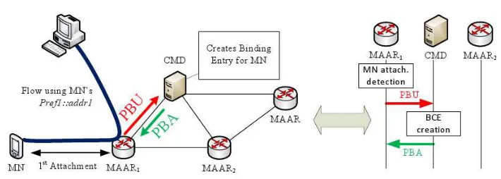
Upon MN’s attachment to MAAR1, an IPv6 global prefix belonging to the MAAR’s
prefix pool is reserved for it (Pref1). The prefix is sent in a PBU with the MN’s Identifier (MN-ID) by the MAAR to the CMD, that, since the session is new, stores a Binding Cache
Entry containing as main fields the MN-ID, the MN’s prefix and MAAR1’s address visible by
the CMD (Proxy-CoA). The CMD replies to MAAR1with a PBA indicating that the MN’s
registration is fresh and no past status is available. MAAR1unicasts a Router Advertisement
(RA) to the MN including the prefix reserved before, that can be used by the MN to configure an IPv6 address (e.g., with SLAAC). The address is routable at the MAAR, in the sense that the node is on the path of packets addressed to the MN; moreover, the MAAR acts as plain
Figure 4.4: Partially distributed PMIPv6: CMD as message relay
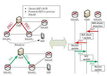
4.2.1 The CMD is a PBU/PBA relay
When the MN moves from its current access, it associates to MAAR2, which delegates
another IPv6 prefix (Pref2) and sends it to the CMD for registration. The CMD has already an entry for the MN, binding the MN-ID to its former locations, thus, it forwards the PBU to
all the MAARs indicated as Proxy CoAs, in this case only MAAR1(as depicted in Fig.4.4).
Upon PBU reception, MAAR1 replies to the CMD with a PBA to ensure that the new
location has successfully changed, containing the prefix anchored at MAAR1. The CMD updates the BCE adding the P-MAAR address in the list of old P-CoAs and forwards the PBA to the new S-MAAR, containing the previous Proxy-CoA and the prefix anchored to it, so that a tunnel can be established between the two MAARs and new routes are set appropriately to recover the flow(s).
Now packets destined to Pref1are first received by MAAR1, encapsulated into the tunnel
and forwarded to MAAR2, which finally delivers them to their destination. In uplink, when
the MN transmits packets using Pref1for the source address, they are sent to MAAR2, as it
is MN’s new default gateway, then tunneled to MAAR1which routes them towards the next
hop to destination. Conversely, packets carrying Pref2 are routed by MAAR2 without any
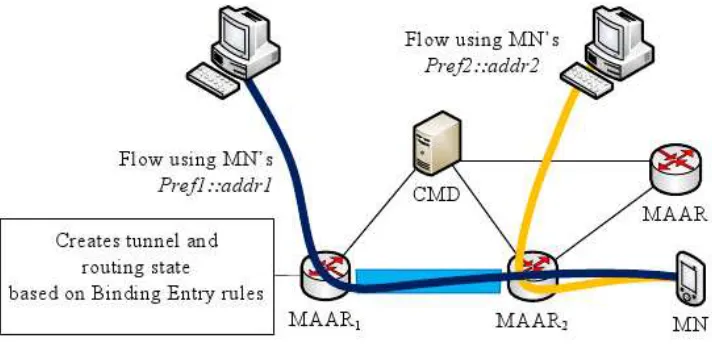
special packet handling both for uplink and downlink (see Figure4.5).
Figure 4.5: Partially distributed PMIPv6: data flow
the A-MAARs.
It should be noted that this design separates the mobility management at the prefix gran-ularity, and it can be tuned in order to erase old mobility sessions when not required, while the MN is reachable through the latest prefix acquired. Moreover, the latency associated to the mobility upadate is bound to the PBA sent by the furthest A-MAAR, that takes the longest time to reach the CMD. The drawback can be mitigated introducing a timeout at the CMD, by which, after its expiration, all the PBAs so far collected are transmitted, and the remaining are sent at a later stage, upon their arrival.
4.2.2 The CMD as MAAR locator
The latency experienced in the approach shown before can be mitigated if the A-MAARs are allowed to signal directly their information to the new S-MAAR. This procedure reflects
what was described in Section4.2.1up to the moment the A-MAAR receives the PBU. At
that point an A-MAAR is aware of the new MN’s location (i.e., S-MAAR) and, besides sending a PBA to the CMD, it also sends a PBA to the S-MAAR including the prefix it is anchoring. The CMD is relieved from forwarding the PBA to the S-MAAR, as the latter receives a copy directly from the A-MAAR with the necessary information to build the
tunnel and set the appropriate routes. In Figure4.6is illustrated the new messages sequence.
4.2.3 The CMD as PBU/PBA proxy
Figure 4.6: Partially distributed PMIPv6: CMD as MAAR locator
the suitable information to establish the tunnel and routes on their side. When A-MAARs complete the update, they send a PBA to the CMD to indicate that the operation is concluded
Evaluation of the DMM solutions
In this chapter we focus on conducting an analysis of the performance achievable by FAMA and the network-based proposals, comparing them with what would be obtained with plain Mobile IPv6 and Proxy Mobile IPv6.
The comparison is performed considering the three most important characteristics of a mobility protocol:
• Packet and signaling overhead;
• Handover latency;
• Delay between the communication endpoints.
5.1
Overhead Analysis
As explained in Chapters3and4, our proposed Distributed Mobility Management
solu-tions are based on Mobile IPv6 and Proxy Mobile IPv6, pushing, respectively, the HA and LMA functionalities to the edge of the network.
It is common to all DMM approaches to allow the traffic to be forwarded without encap-sulation whenever the communication is started using the address configured in the access network where the MN is currently attached to. This is a clear advantage compared to the centralized schemes, as the tunnels are not always required when the MN is away from home. This scenario is worsened in a PMIPv6 domain, in which the concept of “home network” is lost, as the data traffic is always tunneled as long as the MN is connected to the domain. The design of a dynamic mobility management scheme is one of the DMM’s objective; next paragraphs provide the numeric details of how a tunnel impacts on the data transfer.
5.1.1 Client-based scenario
Once an MN moves, the “home” DAR is in charge of tunneling the packets to the new MN’s location, identified by its care-of address. In terms of packet’s overhead, FAMA and Mobile IPv6 (without Route Optimization) share the same overhead since both use a bi-directional tunnel between the MN and an anchor point, hence both incur in a 40-byte
overhead due to the packet encapsulation. However, as mentioned before, when an appli-cation is restarted, or a communiappli-cation refreshed, the MN uses the appropriate IP address configured in that access network, thus the encapsulation is no more required.
Nevertheless, as compared to Mobile IPv6, in FAMA there may be more than one mobil-ity anchor involved, and therefore this introduces a higher signaling load, since the number of BU/BA messages is increased. In particular, in plain Mobile IPv6 there is a single BU/BA exchange at each handoff – as only one home address is maintained by the MN – while in FAMA we have the BU/BA (and the CoTI/CoT in case additional security is required)
ex-change multiplied byn, given thatnis the number of IPv6 addresses that need to be kept
reachable (or, equivalently, the number of visited access routers). Hence the total amount of
messages is2n(+2nin case of additional security).
5.1.2 Network-based scenario
As described in the previous paragraph, when the MN is not at home the traffic is tun-neled, carrying 40 extra bytes for the encapsulation. Unlike the host-based scenario, how-ever, the encapsulation is performed among network nodes, saving the packet overhead in the radio link. This can be a desired effect in terms of terminal’s efficiency, as it does not waste energy to send/receive unwanted bytes in the communication. More, it should be noted that, in plain PMIPv6, the encapsulation takes always place, whereas network based DMM saves the tunnel when the MN is using the prefix advertised by the current S-MAAR. The evaluation of the message number required to update the routing state of the network nodes proceeds considering separately the fully distributed approach and the partial one.
Fully distributed approach
Regardless the method adopted to learn that a handover occurred, the target MAAR
has a PBU/PBA handshake with n other MAARs, that is, given that n is the number of
IPv6 addresses that need to be kept reachable (or, equivalently, the number of visited access
routers so far), a total of2nmessages.
When the IEEE 802.21 infrastructure is deployed, many more messages are added to the handover phase, but, still, no additional messages are necessary for the IP address continu-ity and routing state update. Also, the extra message exchanges happen before the actual handover, so no extra delay or packet loss occurs.
Partially distributed approach
The three procedures proposed to access the CMD produce different effects on the pro-liferation of messages:
• CMD as message relay. Once the CMD receives the first PBU from the new MAAR
• CMD as MAAR locator. In this case the amount of PBU and PBA messages grows as3n+ 1: the first PBU sent by the new S-MAAR +nmore forwarded by the CMD
to old MAARs +2nPBAs sent back by old MAARs to the CMD and the S-MAAR.
• CMD as message proxy. We have a first handshake with the CMD and the S-MAAR
andnsubsequent message exchanges with the old MAARs, resulting in2n+ 2
mes-sages in total.
5.2
Handover latency
The handover latency corresponds to the time during which an IPv6 address is not us-able because of a change of the point of attachment. During this process there are multiple operations performed like the layer-2 attachment, the movement detection, the address con-figuration and duplicate address detection, and the mobility signaling. In the following we explain the different components of the handover delay:
• Layer-2 handover time (TL2ho). This is defined as the time required by the layer-2
technology to perform a handover (i.e., disconnecting from its current point of attach-ment and connecting to a new one).
• Movement detection time (TM D). This delay corresponds to the time required by the
terminal to detect that it has moved to a different layer-3 point of attachment. In IPv6 this can be done in different ways. The most simple (and the most widely supported) consists in the appropriate use of the Routing Advertisement (RA) messages. An access router periodically multicasts unsolicited RA messages. Movement detection can also be assisted by the use of layer-2 triggers, such the ones implemented by IEEE 802.21. In this case, the movement detection delay can be extremely low.
• IP address configuration and Duplicate Address Detection (TDAD). This time
corre-sponds to the configuration of the IP address based on the prefix received in the RA (i.e., the MN uses stateless auto-configuration) and the address uniqueness test in the network.
• Network authentication delay (Tauth). The handover delay also depends on the
partic-ular authentication method used in the network being accessed by the user terminal.
• Mobility signaling delay (Tbinding). This is the time required to update the mobility
anchor (i.e., HA, DAR, LMA or MAAR) with the new location of the MN (i.e., its CoA or P-CoA) and it highly depends on the distance between the entities participating in the user mobility management: the mobile node on the one side and the HA/DAR on the other side, for the host based approach, the MAAR and MAAR-to-CMD distances for the network-based solutions.
Hence, we can express the handover latency as follows:
in which the most crucial component isTbindingas it depends on the RTT among the network nodes, whereas the first 4 addends can be considered common to all the scenarios mentioned before, since they do not depend from the IP mobility scheme used. We will see later that this is not totally true for IEEE 802.21 case, as its scope is to cut down the layer-2 operations, but, still, our purpose is to deploy a more efficient scheme at layer-3 level, reducing at most the binding phase.
The termTbindingcan be expressed for the different scenarios as follows:
• MIPv6:
Tbinding =RT TM N−HA (5.1)
• FAMA:
Tbinding =RT TM N−HDAR (5.2)
• PMIPv6:
Tbinding =RT TM AG−LM A (5.3)
• Fully distributed network-based DMM:
Tbinding=RT TM AARS−M AARA (5.4)
• Partially distributed network based DMM, CMD as message relay, see Figure4.4:
Tbinding = RT TM AARS−CM D+RT TM AARA−CM D
≈ 2·RT TM AAR−CM D (5.5)
• Partially distributed network based DMM, CMD as MAAR locator, see Figure4.6:
Tbinding = RT TM AARS−CM D+RT TM AARA−CM D+RT TM AARS−M AARA 2
≈ RT TM AAR−CM D+
RT TM AARS−M AARA
2 (5.6)
• Partially distributed network based DMM, CMD as message proxy, see Figure4.7:
Tbinding = max(RT TM AARS−CM D;
RT TM AARS−CM D+RT TM AARA−CM D
2 )
≈ RT TM AAR−CM D (5.7)
FAMA is better suited for flows with short duration or mobile nodes with low mobility. This characteristic is explored in more detail in the next section.
Similarly, from (5.3) and (5.4), we can see that a DMM solution produces a shorter la-tency as long as the A-MAAR is closer to the S-MAAR/MAG than the LMA. This parameter strictly depends on the size of the operator’s network, but, as said in the previous paragraph, we can assume that the LMA is always farther than A-MAARs for short communications with limited user mobility patterns.
Moreover, it can be noted by inspecting (5.5)-(5.7), that the latter solution with the CMD as message proxy outperforms all the others partially distributed proposals. Unfor-tunately, compared to full distribution, as the CMD needs to be at almost the same distance to the MAARs, it might result quite far from the network’s edge, hence approaching the
RT TLM A−M AGdistance typical of PMIPv6.
One last word worth mentioning is the experimental study in [27], in which handovers in a PMIPv6 domain are co-ordinated by IEEE 802.21. In the results proposed after the mea-surement tests, it was shown that, even with the assistance of IEEE 802.21 (i.e., a terminal hands off only when the resources on the target access point are ready), a handover takes a fixed amount of time (around 20 ms) for the attachment/detachment phase, plus a variable interval due to the mobility signaling, that depends on the distance between nodes. Authors of [27] claim that the fixed interval cannot be reduced, as is it the time necessary for the network cards to associate to another access point, whilst all the other handover operations are performed before handing off. Therefore, intervening on the IP mobility scheme could be the only solution to decrease the handover latency. For these reasons, the IEEE 802.21 + DMM mobility management technique is supposed to produce the fastest handover.
5.3
Communication delay
We next analyze of the delay experienced by packets exchanged between an MN and its communication peer (i.e., a CN).
In Mobile IPv6, user data traffic always traverses the HA, although this path may not be the shortest one between the MN and the CN. This way of forwarding packets is known as angular routing and is characterized by delays that might get to be large, since the packets must go through the MN’s home network, which can be located at a long distance from the MN. Due to the large delays introduced by the angular routing, MIPv6 [19] already includes a procedure called Route Optimization that basically builds a secure direct path between the MN and the CN. Hence packets exchanged between MN and CN flow directly through the shortest path between the two nodes, without passing through the HA. This mechanism needs additional support from the CN, required to enable the route optimization of packets. In the case of FAMA, packets flow between the MN and the CN through the HDAR as in the case of Mobile IPv6 without RO. The difference between both approaches is that in the case of FAMA, DARs are expected to be located near the MN, hence the effect of triangular routing is highly minimized, obtaining delays of the order of RO-enabled Mobile IPv6. In the previous section, it was mentioned that the use of FAMA is better suited for flows with short duration or low mobility MNs. This is due to the fact that as the MN moves away from the HDAR handling a flow, the inefficiency introduced by the angular routing increases.
they are either routed through the shortest path or to another MAAR first, and then to desti-nation. Basically, we experience the same issue described for FAMA and the DARs: as long as the user is not getting too far from the A-MAAR, the effect of angular routing is lower than that introduced by traversing the LMA.
In order to assess how far and how fast an MN can move, we perform the following analysis. Lets suppose a VoIP communication between two peers, being one of them an MN using one of the DMM schemes to handle its mobility. Considering the maximum mouth-to-ear delay as specified in [18] of 150 ms, we can assume that (5.8) holds:
TCN→HOM E−AR+THOM E−AR→M N ≤150ms (5.8)
in whichH OM E−ARstands for HDAR or A-MAAR according to the appropriate
situa-tion.
Let’s assume the CN and MN to be in the same geographical region or even city. In
order to model this delay, we took average values from the PingER project1, between several
client-server pairs located in the same regional area. The average delay obtained corresponds to roughly 20 ms, hence from (5.2) the delay between the HOME-AR and the MN is upper bounded by 130ms. Assuming that the DMM domain has a good internal connectivity and is all managed by the same provider, we can conclude that the delay between two DARs (or two MAARs) is similar to a local delay between two servers located in the same organization from the PingER project (which is on average equal to 5 ms). To simplify, we suppose the access network is deployed in such a way that going farther away from the original HOME-AR increases the delay in a linear way (note that this is a worst case scenario). The maximum number of hops allowed for the VoIP communication can then be derived from (5.8), resulting in a maximum distance of 26 hops. This number represents a limit on the diameter of the DMM domain, which depends on the access technology used.
The same delay assumptions hold for centralized approach, but we have to consider also the the angular routing intrinsic in MIPv6 or PMIPv6. So, for instance, we can assume that the distance between an MN and CN is twice the client-server distance mentioned before: one to get to the HA/LMA, and another to reach the recipient (we can safely assume that the anchor is equidistant from the communication endpoints, as they are all located in the same region). With these assumptions, after 4/5 hops DMM degrades as a centralized scheme. However, the advantage of DMM is that when the delay becomes not tolerable, the applica-tion might be restarted, or the communicaapplica-tion refreshed, so that the most suitable IP address can be picked, thus leading to traverse a shorter (direct) path with better delay.
In the case of a WAN technology such as WiMAX or 3G, one access router can serve a cell of about 50 Km of radius, while in the case of a LAN technology such as IEEE 802.11, the cell radius is reduced to less than 100m. Now let’s look at a typical use case, where a user starts a VoIP conversation and walks across a DMM domain using IEEE 802.11. The typical speed for pedestrians is 4-5 Km/h [22] and the average call duration is roughly 3 minutes [30]. This means that during the call, the user will walk around 250m, hence performing two handovers and adding a delay of roughly 10ms more than the direct path between the CN and MN. This simple example shows two of the benefits of DMM: simplicity and low added end-to-end communications delay.
1
5.4
Final remarks
One might argue that a DMM approach produces location updates more often than a centralized one, resulting in an increased signaling overhead.
Figure 5.1: Edge network divided in IP access cells
Actually the update frequency is a parameter left to the operator’s choice as it is strictly
related to the network conformation. For the sake of clarifying this concept, Figure5.1
Conclusions
In this thesis we have proposed and analyzed different solutions for distributed mobility management based on a host-based mobility protocol as Mobile IPv6 and also based on a network-based one as Proxy Mobile IPv6.
These solutions bring the advantages of a distributed approach, namely shorter data paths, better scalability and reliability, shorter handover latencies, and better control on the mobility granularity offered by the network. Unfortunately they come at the cost of an in-creased overhead due to the proliferation of control messages, but it should be noted that, if some intelligence is implemented to determine whether applications need mobility or not, with our DMM approach we can avoid setting up unnecessary mobility session, thus sav-ing the related signalsav-ing. If we push this situation to the extreme, we can enable mobility dynamically only when an application that cannot survive an IP address change is running.
Envisioning such smart interaction between applications and mobility stack, we claim that FAMA is a straightforward solution as the two processes run on the same system, whereas a network-based technique is more interesting from a research perspective. More-over, in the FAMA architecture, two different levels of security protection are proposed,
allowing for a faster and easier deployment with respect to the use of IPsec1.
Nevertheless, client solutions suffer from several limitation due to the hosts’ features: legacy terminals need to be upgraded in order to benefit of DMM technique. In addition, the mobility signaling and the subsequent tunnels are responsibility of the MN, with the undesired effect of introducing extra energy consumption due to the over-the-air control messages and the packet overhead in the data communications
For these reasons, network-based DMM solutions have been researched as well, trying to stretch PMIPv6 to adapt to a flat network. Indeed, current mobility solutions used in real operator networks are network-based – as the GPRS Tunneling Protocol (GTP) –, hence it is reasonable to go through network-based DMM solutions as well. A preliminary work on the subject was developed in [16]. Here we re-elaborated with more detail the topic, describing the fully distributed approaches, where the data plane and the control plane is handled by the edge routers only, and we researched partially distributed approaches as well, in which the data plane is distributed among the edge routers, but the control plane is co-ordinated
1FAMA design was honored with the Best Paper Award at Mobiworld 2011, a workshop co-located with
IEEE INFOCOM 2011, Shanghai, China, April 2011, and was also presented at the 80th IETF Meeting in Prague, Czech Republic, April 2011 [3]