Intelligent PID Controller on Soft Computing
Honghua Xu, Xiaoqiang Di
Changchun University of Science and Technology, Changchun, China Email :{honghuax,xiaoqiangd}@126.com
Huamin Yang, Guangcai Cui
Changchun University of Science and Technology, Changchun, China Email : {huaminyan,guangcaicu}@yahoo.com
Abstract—The PID control algorithm is used for the control of almost all loops in the process industries, and is also the basis for many advanced control algorithms and strategies. For complex systems, controller’s structure and parameters need to rely on experience and on line tuning to determine. Application of soft computing techniques can realize self-tuning of controller parameters. In this paper, the author applies fuzzy system, neural network technique and genetic algorithm to PID controller in order to achieve intelligent adjustment the controlled variables. Simulation results show that the application of soft computing techniques in the controller has better control quality.
Index Terms—intelligent, fuzzy system, neural network, proportion integration differentiation, genetic algorithms
I. INTRODUCTION
PID(Proportion Integration Differentiation) control is one of the best widely applied controlling methods in industrial producing process because it is simple and robust[1].
Conventional PID control is a most common method used in the process of manufacturing. It has found its application in many trades. It has many advantages such as ease of controlling, ease of realizing and debugging on the spot etc[2]. In the actual control process, the controlled process is nonlinear, time-varying and indefinite, especially for some more complicated systems. Conventional PID is hard to meet this requirement.
In the actual design of control system, there still exists trial and error method to solve[3]. With quick development of relative technology, control system needs higher norms and self-adaptation technique of PID control parameters in order to suit for more complicated situations and higher demand for norms. So the control engineers are on look for automatic intelligent tuning procedures.
In this paper, the parameters of PID controller are tuned for controlling some rock mechanics testing machine[4]. Conventional PID performance has been compared and analyzed with the intelligent tuning techniques like fuzzy system, neural network, and Genetic algorithm. Soft computing techniques based tuning methods have proved their excellence in giving better results by improving the steady state characteristics.
II. PID CONTROL MECHANISM
A. PID algorithm in analog system
In simulation system, the equation of PID algorithm[5] is:
( )
1
U( )
P( )
( )
DI
de t
t
K
e t
e t dt T
T
dt
⎡ ⎤
⎢ ⎥
⎢ ⎥
⎣ ⎦
=
+
∫
+
(1)Where,
U t
( )
is the output signal of regulator;e t
( )
is the error signal of regulator, which equals to the difference between measurement value and preset value;P
K
is the proportional coefficient of regulator;T
I is the integral time of regulator;T
D is the differential time of regulator.B. Digital PID Algorithm
Because computer control is a sampling control, it can only calculate control volume according to the error of the sampling moments[2,6]. Therefore, in the process of computer control, we must make dispersed treatment to equation (1) to use digital difference equation to take the place of differential equation in successive system. Then integral term and differential term can be expressed with summation and increment equation.
0
0 0
( )
( )
( )
n n
n
j j
e t dt
e j
t
T
e j
= =
Δ
=
∑
=
∑
∫
(2)( )
( )
(
1)
( )
(
1)
de t
e k
e k
e k
e k
dt
Δt
T
−
−
−
−
≈
=
(3)We put (2) and (3) into (1) and then we can get dispersed PID equation.
[
]
0
( ) ( ) ( ) ( ) ( 1)
U
k
D P
j I
T T
k K e k e j e k e k
T = T
=
⎧
⎨
+ + − −⎫
⎬
⎩
∑
⎭
(4)
moment;
k
is sampling serial number,k
=0, 1, 3, …;( )
U k
is the regulator output of No.k sampling moment. From equation (4), if we want to getU( )
k
, not only do we need the error signalse k
( )
ande k
(
−
1)
, of this time and last time but we need plus previous errorsignals
e j
( )
from integral term, i.e. 0( )
k
j
e j
=
∑
. By this way, it is quite complicated to calculate, however, there needs much memory to storee j
( )
. So it is quite inconvenient to control directly with equation (4). Let’s adjust it as follows:[
]
1
0
U( 1) E( 1) ( ) ( 1) ( 2)
k
D P
j I
T T
k K k E j E k E k
T T
−
=
− = ⎧⎨ − + + − − − ⎫⎬
⎩
∑
⎭(5)
Subtract equation (5) from equation (4), we can get:
[
]
[
]
U( )
U(
1)
( )
(
1)
( )
( ) 2 (
1)
(
2)
P
I D
k
k
K
e k
e k
K e k
K
e k
e k
e k
=
− +
−
−
+
+
−
− +
−
(6)Where, I P
I
T
K
K
T
=
is integral coefficient;D
D P
T
K
K
T
=
is differential coefficient.From equation (6), to get the output value
U( )
k
, it is ok to getU(
k
−
1)
,e k
( )
,e k
(
−
1)
ande k
(
−
2)
. It is much easier than using equation (4).Although equation (6) is revised only a little bit, it brings the following advantages.
(1). Because the output is increment, it has small influence of malfunction.
(2). It’s easy to realize the non-interfering switches of control patterns.
(3). No integral out of control. It’s easy to get better regulation quality.
III. SOFT COMPUTING TECHNIQUES
A. PID Controller on Fuzzy System
Fuzzy system is a system based on knowledge or rules. Its core is knowledge base made up of so-called IF-THEN rules which come from experts or the knowledge in this field[7-9]. Then, we apply all these rules to single system. Different fuzzy systems should adapt to different combination rules.
1. fuzzy system
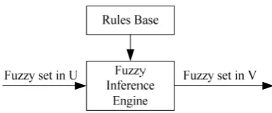
The basic structure of a pure fuzzy system is as shown in Figure 1. Rule base can be shown as a set of several IF-THEN rules. Through combing these IF-THEN rules, fuzzy inference engine will decide how to map the fuzzy set of input domain of discourseU ⊂Rn on the fuzzy set of output domain of discourseV ⊂R.
Figure 1. The structure of a pure fuzzy system.
The leading problem of a pure fuzzy system is that its input variable and output variable are all fuzzy sets, whereas, the input and output in engineering system are all real-valued variables[10,11].
To apply fuzzy system to engineering system, a simple method is to add a fuzzifier at the input end. Its purpose is to change the real-valued variable to a fuzzy set. At the output end, we add a defuzzifier, which is to switch the fuzzy set to real-valued variables. Figure 2 shows us a fuzzy system with a fuzzifier and a defuzzifier.
Figure 2. The structure of a fuzzy system with a fuzzifier and a defuzzifier.
Rule base is composed of fuzzy IF-THEN rule set. It is the core of a fuzzy system. Other components of a fuzzy system carry out these rules in a reasonable and efficient way. Rule base consists of the following IF-THEN rules.
( )
1 1
: ... ,
l l l l
u n n
R If x is A and and x is A then y is B (7) Where, Ail and
l
B are fuzzy set of Ui ⊂R and V ⊂R respectively, ( ,1 2,..., )
T n
x= x x x ∈U and y∈V
are input and output variables of the fuzzy system. To provide a general knowledge equation, equation (7) consists of the following rules:
(1). “incomplete rule”
1 ...1 ,
l i l
m m
If x is A and and x is A then y is B in m<n
(2). “or rule”
1 ...1 1 1
... ,
l l l
m m m m
l l
n n
If x is A and and x is A or x is A
and and x is A then y is B
+ +
(3). “single fuzzy statement”
l y is B (4). “stepwise variation rule”
,
If x is smaller then y is bigger
The function of a fuzzy inference engine is to compound the mapping of a fuzzy IF-THEN rule which
'
U on fuzzy set
B
' in V. Fuzzy inference engine is designed according to the following rules.(1). In conformity with the experience of experts.
(2). High computer efficiency.
(3). Specific requirements of some features.
Product inference engine has the advantage of ease of computing and can directly reflect actual problems. Its equation is as shown in equation (8).
' ' '
1
1
( ) max[sup( ( ) l( ) ( ))]
i
n M
i
B l A A B
x U i
y x x y
μ μ μ μ
= ∈
=
=
∏
(8)If you offer a fuzzy set A'in U, the inference engine can product a fuzzy B' in V.
A fuzzifier can be defined as a mapping of
* n
x ∈ ⊂U R on fuzzy set '
A in U. The fuzzifier is designed according to the following rules.
(1). The fuzzifier should consider the fact that it is at clear point *x that input occurs.
(2). If the input of a fuzzy system is interfered by noise, the fuzzifier needs the ability to overcome the influence of noise.
(3). The fuzzifier should contribute to simplify the computing of fuzzy inference engine.
The triangle fuzzifier maps *x ∈Uon fuzzy set ' A in U. It has the following triangle membership function.
'
* *
1- 1 - *
-1
(1- )*...*(1- ) ( 1, 2, , )
( )
0
n n
n n i
A n
x x x x
in x x b i n
x b b
others
μ ⎧
⎪ ≤ = …
= ⎨ ⎪ ⎩
(9) Where, parameter b ii( =1, 2,…,n) is positive number, t-nom * usually chooses algebraic product operator or min operator.
A defuzzifier can be defined as a mapping of fuzzy set '
B (output of the fuzzy inference engine) in V⊂Ron *
y ∈V . Defuzzifier methods should consider the following rules.
(1). Point *
y should visually represent ' B.
(2). Ease of computing is quite important because of controller’s real-time operation.
(3). Continuity is needed. Slight change of '
B shouldn’t cause substantial variation of *
y .
The center average defuzzifier can be defined as the following equation (10).
* 1
1 M
l l l
M
l l
y y
ω
ω
=
=
=
∑
∑
(10)Where, yl is the center of the lth fuzzy set; ωl is the
height. The center average defuzzifier is ease of computing, reasonable and visual.
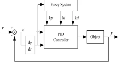
2. The structure of pid controller with fuzzy system The PID controller with a fuzzy system takes error e and error variation ec as its input. It utilizes fuzzy system to tune PID parameters on line, which can satisfy the requirements of different
e
andec
to PID parameters’ adaptation. Its structure is as shown in Figure3.Figure 3. The structure of PID controller with a fuzzy system.
where the core of the PID controller is to build up fuzzy rule base on the basis of engineering technicians’ knowledge and actual operation equation. The fuzzy sets of e and ec are {NB,NM,NS,O,PS,PM,PB} in which all the components stand for negative big, negative medium, negative small, zero, positive small, positive medium, positive big. The following fuzzy rules are established.
If (e is NB) and (ec is NM) then (kp is PB)(ki is NB)(kd is NS)
If (e is NM) and (ec is PS) then (kp is PS)(ki is NS)(kd is NM)
……
If (e is PM) and (ec is NB) then (kp is PS)(ki is Z)(kd is PB)
If (e is PB) and (ec is PM) then (kp is NB)(ki is PB)(kd is PS)
B. PID Controller on RBFNN
Radial basis function neural network (RBFNN) is a three-layer feed forward[12]. With radical basis function network, we can construct a self-learning PID controller with parameters
k k
p,
i andk
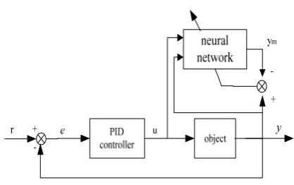
d.1. Structure of Neural Network PID Controller
The PID control strategy based on neural network is shown in Figure 4. The regulator consists of two parts:
PID controller can directly closed-loop control the objects and three parameters
k k k
p, ,
i d can be adjusted on line.Figure 4. Structure of neural network PID controller
Where,
r
is the system input, andy
is the system output.y
m is the output of neural network.u
is the output of PID controller.2. Neural Network Identification Algorithm
Radial basis function neural network consists of input layer, hidden layer and output layer, in which input layer consists of signal source nodes, the number of units in hidden layer is decided by the need of the described questions and output layer responds to the input layer[15]. The mapping from input to output is nonlinear, whereas the mapping from hidden layer space to output space is linear. Therefore, the learning speed will be much faster and at the same time local minimum problems will be avoided.
Suppose neural network is made up of n input nodes, m hidden nodes and one output node. In the structure of neural network, the input vector of network input layer can be expressed as
X
=
[ ,
x x
1 2,... ]
x
n T , the radial basis vector of the network hidden layer can be expressed as=
[ ,
1 2,
...
]
Tj m
H
h h h
h
, whereh
j is radial basis function may choose different algorithms. Here, we’d like to choose Gaussian function, i.e. (11).2
2
exp
,
1, 2,...
2
⎛
−
⎞
⎜
⎟
=
−
=
⎜
⎟
⎝
⎠
j j jX
C
h
j
m
b
(11)Where,
C
j is the center vector of No.j node in network. The expression is as follows:1
,
2,... ...
, (
1, 2,... )
⎡
⎤
=
⎣
⎦
T=
j j j ji jn
C
c
c
c
c
i
n
(12)Suppose the base width vector of the network is
[
1, ...
2]
T m
B
=
b b
b
,b
j is the base width parameter ofnode j and
b
j is greater than zero. The network weightvector is
W
= ⎣
⎡
w w
1,
2...
w
j...
w
m⎤
⎦
T . The output expression of identification network is as follows.1
( )
m
m j j
j
y
k
w h
=
=
∑
(13)In order to obtain better result of network identification, while revising weight coefficient, an
gradient descent, the interactive algorithm of output weight, node center and node width parameter can be expressed as equations (14) (15) and (16)
=[ ( ) ( )]
( ) ( 1) [ ( 1) ( 2)]
+ [
( -2)-
( -3)]
j m j
j j j j j
j j
W y k y k h
W k W k W w k w k
W k W k
η
α
β
Δ − = − + Δ + − − − (14) 2 3 [ ( ) ( )]( ) ( 1) [ ( 1) ( 2)]
+ [ ( 2) ( 3)]
j
j m j j
j
j j j j j
j j
X C
b y k y k w h b
b k b k b b k b k
b k b k
η
α
β
− Δ = − = − + Δ + − − − − − − (15) 2 [ ( ) ( )]( ) ( 1) [ ( 1) ( 2)]
+ [ ( 2) ( 3)]
j ji
ji m j
j
ji ji ji ji ji
ji ji
X C
c y k y k w
b
c k c k c c k c k
c k c k
η
α
β
− Δ = − = − + Δ + − − − − − − (16)Where,
η
is learning rate, andα
,β
is inertia coefficients whose value range is between 0 and 1.The sensitivity information algorithm of the output of the controlled object to the control input is as follows.
1 1 2 1
( )
( )
( )
( )
m j m j j j jc
x
y k
y k
w h
u k
u k
=b
−
∂
∂
≈
=
∂
∂
∑
(17)In the actual application,
x
1 is the input term of identification network and its value isu k
( )
.3. PID Parameter Tuning Principle online According to Figure 4, control error is:
( )
( )
( )
e k
=
r k
−
y k
(18) Suppose there are parametersc c c
1,
2,
3 .1
2
3
( )
(
1)
( )
( ) 2 (
1)
(
2)
c
e k
e k
c
e k
c
e k
e k
e k
=
−
−
=
=
−
− +
−
PID control strategy uses equation (6) to calculate.
1 2 3
( )
(
1)
p i du k
=
u k
− +
k c
+
k c
+
k c
(19)Neural network tuning target is :
2
1
( )
( )
2
E k
=
e k
Low gradient descent should be adopted to adjust parameters
k
p,k
i andk
d . Its calculation process is as follows:1
( )
p
p p
E
E y
u
y
k
e k
c
k
y u k
u
η
∂
η
∂ ∂ ∂
η
∂
Δ = −
= −
=
∂
∂ ∂ ∂
∂
2
( )
i
i i
E
E
y
u
y
k
e k
c
k
y
u k
u
η
∂
η
∂ ∂ ∂
η
∂
Δ = −
= −
=
∂
∂ ∂ ∂
∂
(21)
3
( )
d
d d
E
E y
u
y
k
e k
c
k
y u k
u
η
∂
η
∂ ∂ ∂
η
∂
Δ = −
= −
=
∂
∂ ∂ ∂
∂
(22)
Where,
y
u
∂
∂
is information of controlled object whichcould be obtained through neural network identification.
C. PID Controller on GA 1. Genetic algorithms
Genetic algorithms (GA), which imitate genetic mechanism and the theory of evolution, is the most optimized parallel random searching method[16,17]. GA introduces the rule of the theory of evolution” survival of the fittest” to the coded string group composed of the most optimized parameters. According to adaptation value functions, GA which selects units through copying, crossing and varying retains high adaptation value units which form new units that inherit the information from previous generation and optimize the previous generation in turn. Repeatedly in this way, the adaptation ability of units is continuously improved till a satisfactory situation. Its algorithm is quite easy and can be concurrently dealt with to get overall optimization.
PID controller to which GA is applied can employ GA to optimize parameters. This method is the one which doesn’t need any initial information and can find the most optimized and the most efficient combination method.
The elements for GA:
(1) Chromosome coded method. Basic GA employs fixed length binit to mark units in the group and its allele is composed of symbol set{0.1}.
(2) Unit’s sufficiency evaluation. The directly proportional probability of GA and unit sufficiency can decide how much probability it will be from the units of current group to the group of the next generation. To correctly calculate the probability, all the sufficiency must be firstly defined from objective function to unit sufficiency.
(3) Genetic operator. Basic GA employs genetic operators which include selection operator which selects operation ratio, one-point crossover operator which employs crossover operation, simple mutation operator which employs mutation operation or uniform mutation operator.
(4) The operation of basic GA demands predetermined parameters:
M: group size i.e. the number of units in the group. G: the last evolution algebra of GA.
Pc: crossover probability. Pm: mutation probability.
2. PID setting principle based on GA
(1). Parameter determination and representation.
At first parameter scope should be determined and this scope should be given by users. Next, in terms of precision, coding should be made. Binary character string should be chosen to represent each parameter and relation should be set up. At last, binary character string should be attached to form a long binary character string which is that object that GA may operate.
(2). Selecting initial population.
Because all the processes can be realized through programming, initial populations are generated by computer random. As for binary coding, firstly evenly distributed random numbers between 0 and 1 are generated[18]. Then 0 stands for the generated numbers between 0 and 0.5; 1 stands for the generated numbers between 0.5 and 1. Besides, the size of population is decided by the complexity of computer.
(3). Fitting function determination.
Under constraint conditions, common optimizing algorithm can obtain a group of satisfactory parameters. In the process of designing, the best parameter should be chosen from this group of parameters. There are three aspects we use to measure the indicators of the controlling system, i.e. stability, accuracy and rapidity. Rise time reflects the rapidity of the system. The shorter the rise time spends, the faster the controlling carries out. (4). GA operation.
At first, we should employ sufficiency ration to copy, i.e. through fitting function we can get fitting value to get corresponding copy probability of each string. The product of copy probability and the number of strings of each generation is the number of strings copied in the next generation. The bigger copy probability is, the more offspring the next generation will have. On the contrary, it will die out.
Through copy, crossover and mutation, initial population obtains a new population, which can be taken into fitting function after decoding. Then we should check if it satisfies termination condition. If not, the above operation will repeat till making it.
In order to obtain satisfactory dynamic characteristics of transient process, performance indicator of error absolute value time should be adopted as the minimum objective function of parameter selection. To avoid excessive control energy, quadratic term of control input should be added to objective function. The following equation is chosen as the most optimized indicator of parameter selection.
2
1 2 3
0
(
| ( ) |
( ))
t uJ
w e t
w u t d
w t
¥
=
ò
+
+
(23)Where,
e t
( )
is the system error.u t
( )
is controller output.t
u is rise time. w1, w2, w3 are weights.2
1 2 4 3
0
(
| ( ) |
( )
| ( ) |)
. ( )
0
t u
J
w e t
w u t
w e t
d
w t
if e t
¥=
+
+
+
<
ò
(24) Where, w4 is a weight and w4>>w1.
IV. EXPERIMENT’S RESULT AND ANALYSIS
Some rock mechanics testing machine has the functions of real-time control, monitoring and feedback. Its control process is nonlinear and highly complicated. The control system asks for realizing automated control with high accuracy and high reliability to the testing machine.
The transfer function of the rock mechanics testing machine system is equation below:
3 2
0.4
( )
0.015
0.523
0.12
G s
s
s
s
=
+
+
Here, traditional PID control algorithm and intelligent PID control algorithm based on soft computing are adopted to respectively make simulation experiment and analysis to the system.
The executive body of the system adopts driving step motor to control. Its control algorithm is as shown in equation (6). The process of control algorithm is as follows:
(1) initializing parameter. (2) sample r k( ) and ( )y k . (3) calculating error value. (4) calculating controller output;
(5) renewing parameters and returning to procedure (2). Controller parameters are set as follows:
p
k
=20,k
i=0.2 andk
d =8. The simulation result is shown in Figure 5.Figure 5. The result of conventional PID.
During intelligent tuning, we define the variation scopes of system error
e
and error variation rateec
as the domain of discourse on fuzzy set and then decide its fuzzy subsets and their membership. While controlling on line, control system together fuzzy system’s handling and computing finishes proofreading to PID parameters(1) Taking current sampling value. (2) Computing ( )e k , ec k( ) and (e k−1). (3) Fuzzifying ( )e k and ec k( ).
(4) Fuzzy adaptation to Δkp, Δki and Δkd.
(5) Computing current
k
p,k
i and kd.(6) Effect of PID controller’s output on the controlled system.
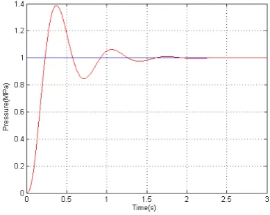
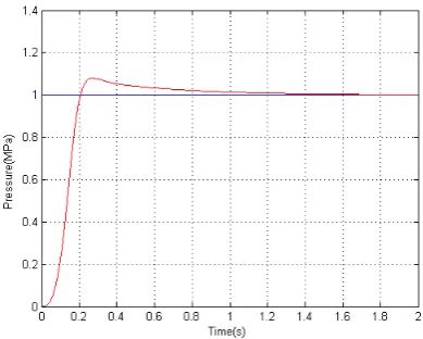
The simulation result is shown in Figure 6.
Figure 6. The result of PID controller on fuzzy system.
The procedures of control strategy using RBFNN are as follows:
(1) Making sure the number of network input nodes, the number of hidden layers, learning rate and inertia coefficient to get center vector of hidden nodes, base width vector of the network and the initial value of weight vector.
(2) Sampling to get input r and output y, and calculating error e in terms of equation (18).
(3) Calculating the output u of regulator according to equation (19) to control the controlled object real time.
(4) Calculating network output ym and adjusting center vector of network hidden nodes and base width vector and weight vector to obtain network identification information.
(5) Adjusting parameters of regulator in terms of equations (20) (21) and (22).
(6) Going back to procedure (2).
The structure of neural network is 3-6-1. The three inputs of network identification are
u k
( )
,y k
( )
and(
1)
Figure 7. The result of PID controller on RBFNN.
The specific procedures of optimizing PID parameters using GA are as follows:
(1) making sure the scope and coding length of each parameter and coding.
(2) generating initial population made up of n random units.
(3) decoding respective parameter value from the population and then using this parameter value to get cost function value and fitting function value. (4) using copy, crossover and mutation operators to
operate population to produce a new population. (5) operating procedures (3) and (4) till parameter
convergence or achieving desired indicator.
Adopting binary coding is to avoid using the length of 10 bits binary coding string to mark three decision variables
k
p,k
i and kd. The equation (24) is used toselect the most optimized indicator. The number of samples used in GA is Size=30. Crossover probability and mutation probability are Pc=0.60, Pm=0.001-[1:1:Size]x0.001/Size. The value span of parameter
k
p is [0.20]. The value span ofk
i and kd is [0.1], w1=0.99,w2=0.001, w3=1.0, w4=100.
The simulation result is shown in Figure 8.
Figure 8. The result of PID controller on GA.
From above Figures, traditional control algorithm needs longer tuning time, rise time and larger overshoot. The controller employing soft computing technique to realize can obtain better tuning performance for the system tuning. The specific comparison is shown in tableI.
V. CONCLUSION
The PID control algorithm is the basis for many advanced control algorithms and strategies in the process industries. In order to use a controller, it must first be tuned to the system. This tuning synchronizes the controller with the controlled variable, thus allowing the process to be kept at its desired operating condition. Conventional PID control method can be used only when the process mode is of a certain type. The study on PID controller using soft computing technique embodies its excellence. Soft computing has the features of intelligence and self-adaptation, so there is no need for the controlled objects constructing precise model. The system has stronger capacity of resisting disturbance. For complicated controlled objects, the system can obtain higher control quality, hence robustness.
While solving complicated actual problems, the system may combine knowledge, techniques and methods of various sources. Various computing models of soft computing technique aren’t mutually exclusive and teamwork will own bigger excellence. The systems employing different computing techniques are regarded as complementary mixed intelligent systems, which will be a further study content.
ACKNOWLEDGMENT
The authors would like to acknowledge the financial support of The Scientific and Technological Key Support Projects with the project number 20090307.
REFERENCES
[1] G. Eason, B. Noble, and I. N. Sneddon, “On certain integrals of Lipschitz-Hankel type involving products of Bessel functions,” Phil. Trans. Roy. Soc. London, vol. A247, pp. 529–551, April 1955.
[2] J.Astrom and T.H.agglund. PID Controllers: Theory, design and tuning. Instrument society of America, 2nd edition, 1995.
[3] Kiam Heong Ang, Gregory Chong: “PID Control System Analysis, Design, and Technology” IEEE Transactions on
TABLE I.
COMPARISON OF STEADY STATE RESPONSES
Peak over shoot (%)
Settling time (sec)
Rise time (sec)
Con. 39.6 2.52 0.362
FS 12.7 0.26 0.067
NN 8.2 1.7 0.261
Control Systems Techonology, Vol.13, No.4, July 2005 pp. 559-576.
[4] Honghua Xu, Guangcai Cui, Ji Li. FuzzyPID Control Technology Application in Rock-testing System. Journal of changchun University of Science and technology. 2005,28(3), pp. 42-45.
[5] Neuron Chip Distributed Communication and Control Processors. Motolora Inc., 1994.
[6] Qing-Guo Wang,Tong-Heng Lee: “PID Tuning for Improved Performance” IEEE Transactions on Controll Systems Technology, Vol.7, No.4 July 1999, pp. 457-465. [7] Gravel, A. and H. Mackenberg, Mathematical analysis of
the Sugeno controller leading to general design rules. Fuzzy Sets and Systems, 85, pp. 165-175, 1995.
[8] Kadmiry B.,Bergsten P. “Robust Fuzzy Gain Scheduled visual-servoing with Sampling Time Uncertainties” IEEE Int. Symposium on Intelligent Control (CSS / ISIC ), Taiwan 2004.
[9] Z. Y. Zhao, M. Tomizuka, and S. Isaka, .Fuzzy gain scheduling of PID controllers,. IEEE Transactions on Systems, Man, and Cybernetics, vol. 23, no. 5, pp. 1392.1398, 1993.
[10]Honghua Xu, Guang Dong, Weili Shi. “An Intelligent PID Controller Based on Fuzzy System”, IEEE Conf. ICEEE2010, vol. 5, pp. 3117-3121, 2010.
[11]Di Nola, A., S. Sessa, W. Pedrycz, and E. Sanchez, Fuzzy Relation Equations and Their Applications to Knowledge Engineering, Kluwer, Boston, 1989.
[12]Honghua Xu, Yinghua Tian. “An Intelligent PID Controller on RBFNN”, IEEE Conf. Electrical Engineering and Automation Control, vol. 4, pp. 1256-1259, 2011.
[13]Cheeseman, P., “An inquiry into computer understanding,” (with discussions) Computational Intelligence, 4., pp.58-142, 1988.
[14]Bonadeo N H, Erland J, Gammon D, et al. Coherent Optical control of the Quantum State of a Single Quantum Dot. Science, 282: pp.1473-1475, 1998.
[15]Karayiannis, N. B. Reformulated radial basis neural networks trained by gradient descent. IEEE Trans. on Neural Networks. 10(3): pp. 657-671, 1999.
[16]Jukka Lieslehto “PID controller tuning using Evolutionary programming” American Control Conference, VA June pp. 25-27, 2001
[17]Hang, C. C. and K. K. Sin, “A comparative performance study of PID auto-tuners”, IEEE Control Syst. Msg., vol. 11, pp. 41-47, 1991.
[18]T. Ota and S. Omatu, “Tuning of the PID control gains by GA,” in Proc. IEEE Conf. Emerging Technol. Factory Automation, Kauai, HI, Nov., pp. 272–274, 1996.
Honghua Xu graduated from Changchun University of Science and Technology in 2004. He is a lecturer at Changchun University of Science and Technology and mainly engaged in teaching and research work. He has participated in some provincial and ministerial research projects. He has presented many papers in journals and international conferences. Main areas of research are computer simulation and artificial intelligence.
Xiaoqiang Di graduated from Changchun University of Science and Technology in 2002. He is a lecturer at Changchun University of Science and Technology and mainly engaged in teaching and research work. He has participated in some provincial and ministerial research projects. He has presented many papers in journals and international conferences. Main areas of research are image processing and artificial intelligence.
Huamin Yang graduated from Dalian
University of Technology in 1985. He is a professor and doctoral tutor at Changchun University of Science and Technology and mainly engaged in teaching and research work. He is a member of the Computer Federation of Province. He has chaired many provincial and national research projects, including some of projects received awards. He has presented more than 70 papers in journals and international conferences. Main areas of research are computer simulation, image processing and artificial intelligence.
Guangcai Cui graduated from Beijing