Page 326 www.ijiras.com | Email: [email protected]
Implementing Droop Controlled DFIG Units In Microgrid
P. Venkata Prasanthi
Student,
EEE Department, JNTUA Ananthapuram
K. Nagabhushanam
Lecturer,
EEE Department, JNTUA Ananthapuram
I. INTRODUCTION
Due to ecological, practical and economic issues, there is unique attention in effective integration of wind based energy sources [1]–[3]. The irregular characteristic of wind is most challenging point. To get the highest obtainable power from wind with variable speed, variable-speed turbine is essential [1]. To handle with this obligation, a doubly-fed induction generator (DFIG) is usually used in type-3 wind turbines since it can be controlled to get the most out of the extracted energy using partial-scale converters with lower ratings as compared to the full-scale back-to-back converter topology used with synchronous generators. It becomes crucial for wind turbines to contribute in frequency regulation to increase supply reliability in microgrid. Yet in the grid-connected mode, many grid codes have altered to permit or even force wind power generation to take part in primary frequency regulation [4]. Major portion of research hard work is dedicated to the utilization of wind turbine rotating mass [5]–[7], while a number of proposals are prepared to afford this energy by deviating from maximum power extraction point [8], [9]. Fascinatingly, frequency droop method, as a replacement for
frequency derivative, conventional inertia emulation, or at least a combination of both [4], [9]–[12] is proposed and this method has more advantages [4], [5]; but a complete study was not given to support these statements. In these works dispatchable source of energy was in use to restore the frequency to its supposed value. Whereas most of the proposed methods for long-term participation of wind in frequency/power regulation approved on deloading and using droop control method, the adopted approaches are different. Most of these methods use wind speed for deloading; but, its exact measurement does not seem easy and pitch-angle is used to deviate from optimum power extraction in [10],while the DFIG torque control and over-speeding [8], [14] are used. It is given in, pitch-angle control is enough for deloading; but the comparison with the other methods tells its slower behavior. It is also recommended that pitch angle can be used for high speed just like as the conventional wind control, while torque can be used for under-rated speeds [4], [14]. Regardless of its advantages, to switch between both control methods this needs wind speed measurement. But in all discussions detailed stability analysis is not given.
Abstract: Wind energy which is an indirect source of solar energy can be utilized to run wind mill, which in turn derives a generator to produce electricity. Energy of wind can be economically used for the generation of electrical energy. In the upcoming days the wind energy is going to be major part of the electric generation. But due to irregular nature of wind, there will be difficulties in power system reliability and stability. In the usual control method the wind turbine generators, usually doubly-fed induction generators (DFIG) do not take part in frequency regulation. But it is very important to use wind generators for self regulation of frequency in microgrid. To solve this problem, in this paper droop control i.e. torque and power droop methods are introduced in DFIG based units. And also how the frequency stability effected is studied. Sensitivity studies, with respect to the presence of turbine- and inverter-based generators in microgrids; and wind speed variation and isolated mode operation with only wind-generators, are conducted. To get improved response Fuzzy Logic Controller is used. Time-domain simulation is used to validate the analytical results.
Page 327 www.ijiras.com | Email: [email protected] Provoked by the abovementioned difficulties, this paper
presents a droop control method to incorporate wind generation in autonomous frequency/power regulation in isolated microgrids, and in weak power grids with reduced inertia. Droop control is implemented on both torque and power by some simple modifications in the conventional DFIG-based wind power controller. Small-signal modeling and eigen-values analyses are employed to distinguish the differences among both methods and gauge their impacts on frequency stability. Sensitivity studies, with respect to the presence of turbine and inverter-based generators in microgrids; and impacts of pitch-angle controller, wind speed variation and isolated mode operation with only wind generators, are conducted. Finally, time-domain simulation results are presented to verify the analytical analysis and discussions. Simulations results are compared with PI and FLC. Fuzzy systems are indicating good promise in consumer products, industrial and commercial systems, and decision support systems. The term ―fuzzy‖ refers to the ability of dealing with imprecise or vague inputs. Instead of using complex mathematical equations, fuzzy logic uses linguistic descriptions to define the relationship between the input information and the output action. In engineering systems, fuzzy logic provides a convenient and user-friendly front-end to develop control programs, helping designers to concentrate on the functional objectives, not on the mathematics.
II. DROOP IMPLEMENTATION IN DFIG
Fig1 shows a DFIG based wind power generator with inter-active control for stiff grid connected and weak grid connected modes. In stiff grid connected mode, the DFIG system need not to be provide voltage regulation and its oprate at unity power factor. In islanding/weak grid connected mode the DFIG regulates its terminal voltage via the rotor side converter (RSC) while the grid side converter is operates at unity power factor to reduce the converter rating. The reference reactive current component was generated by terminal voltage.
In stiff grid connected mode, a DFIG is controlled to extort the highest obtainable power/torque, and it does not include in frequency/active power regulation. In the islanding/weak grid mode, it entered to droop control, which may be torque-droop or power-droop. The reference active current component was generated by the reference torque. The RSC currents are controlled by using Conventional proportional-integral (PI) controllers. To include wind in microgrid frequency regulation and apply droop, adequate reserve power should be considered in wind power generation.
The optimum torque, for constant pitch-angle is Te,opt=Koptωr2(1)
Where ωris DFIG rotational speed
By multiplying the right term of (1) with a deloading factor Kf, the operating point will deviate from the maximum extraction point. The impact of Kfon the wind generation output and rotational speed is shown. Although this deviation could be accounted as a loss, it allows the droop implementation:
Te,deloaded=KfKoptωr2 (2)
A. TORQUE-DROOP
The power/frequency droop is given by P=Pn-(ωm*- ωm)/Kp(3)
Where ωm is angular frequency of microgrid, ωm* is the microgrid preset frequency
The modified equation of (1) given by
Te,TrDr-ref=KfKoptωr2 -mp(ωm*- ωm) (4) Where mp is the droop factor
To examine the effect of this modification, should model the wind power generation with the wind turbine and also need DFIG and the back-to-back converter.
Pm-Pe = 2HDFIGωrdωr/dt(5) Pm = 0.5ρCp(λ,β)Arvω
3 (6)
Where HDFIG is inertia constant, Pe is electrical active power output, Pm is mechanical input to turbine, ρ is air density, Cp is the power coefficient of the wind turbine, λ is tip ratio, Ar is effective area covered by turbine blades, β is pitch angle and vω is wind speed.
For small signal analysis (5) and (6) are modified as (7) and (8) respectively
ΔPm-ΔPe = 2HDFIGωrdΔωr0/dt (7) ΔPm = A1Δ β + A2Δωr+A3Δvω (8) Where
A1= =0.5ρArvω3 (9) A2= =0.5ρArvω3( ) (10)
A3= =0.5ρAr(3CpVω02+vω3 (11)
The output power with torque droop is given by
ΔPe,TrDr(s)= Δvω(s)+
Δωm(s) (12)
B. POWERDROOP
The term mp(ωm*-ωm) in the denominator is replaced by reference torque is given as
Te,PoDr-ref = Koptωr 2
-mp(ωm*-ωm)/ ωr(13)
The output power with power droop is given by
ΔPe,PoDr(s)= Δvω(s)+
Δωm(s) (14)
Here the steady state and dynamic behavior will be changed.
C. STEADY-STATE ANALYSIS
The steady-state response wind power generation to change in frequency regulation with torque droop is given by
ΔPe,TrDr,ss= Δωm (15)
The steady-state response wind power generation to change in frequency regulation with power droop is given by
Page 328 www.ijiras.com | Email: [email protected] factors for torque and power droop are given by (17) and (18)
respectively
meff,TrDr= mp.Keff.TrDr
=mp. (17) meff,PoDr= mp.Keff.PoDr
=mp. (18) The value of kf should be lower than one, higher than one is undesirable and it was shown I fig5. The maximum possible droop factor is given by (19).
mp,max= (19) mp,max= (20)
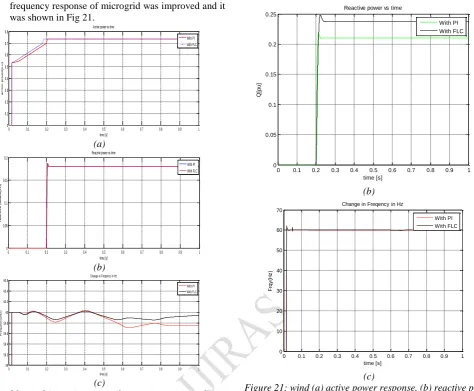
III. STABILITY ANALYSIS
Figure 1: System under-study
For more studies, a medium-voltage rural distribution system, a real system shown in Fig. 1, is considered. The section after the circuit breaker B2 has the capability to work in islanded mode and constitutes the microgrid. The general load of this section is 3.77 MW/1.24 MVAr. It has two DG units where DG1 is a variable-speed wind turbine connected to a 2.5 MVA DFIG with its rotor interfaced by back-to-back converters and DG2 is a 2.5MVA synchronous generator with droop and excitation control systems. System parameters are given in the Appendix. The stability analysis could be extended to larger microgrid or weak grids which experience from reduced inertia.
IV SIMULATION RESULTS
Figure 2: Simulink model
Time-domain simulation, using Matlab/Simulink®, is used to verify the analytical results using the system understudy shown fig2. Here two cases are studied, the first case uses both wind and gas turbine generators, whereas the second uses only wind power generation and again each case has different methods. DG2 is modeled based on details discussed in. The droop and excitation system models are also incorporated. Typical distribution system lines, with low X/R ratio(X/R=2), are modeled as lumped R-L and the loads as parallel R-L elements. System parameters are given in Appendix.
A. GAS TURBINE PLUS WIND
Firstly, constant wind speed is considered to reduce the difficulty. Later, to present a more realistic case, a real wind speed pattern is used.
a. CONSTANT WIND SPEED
Under-Rated Speed: An intended islanding occurs at
t=35s.The system frequency without wind-droop and with power- or torque-droop at various droop gains was observed in fig3. Here both the final frequency and the transient behaviors are improved even with the low X/R ratio. It also confirms larger mp results in improved dynamic behavior.
30 35 40 45 50 55
59.4 59.6 59.8 60 60.2 60.4 60.6 60.8 61 61.2
time(sec)
fre
qu
en
cy
(H
z)
Figure 3(a): Frequency response when wind speed is 13 m/s and Kf=0.5 for no droop
30 35 40 45 50 55
60 60.05 60.1 60.15 60.2 60.25
time(sec)
fre
qu
en
cy
(H
z)
power droop mp=40 power droop mp=80 torque droop mp=40 torque droop mp=80
Figure 3(b): Frequency response when wind speed is 13 m/s and Kf=0.5 for different droop gains
Under-Speeding: It was earlier shown that choosing
higher kf i.e. greater than one may effect in negative effective droop. The wind generator output when kf=1.5 was examined. While the system has extreme generation similar to the pervious case, and frequency has greater than before after islanding, the wind power output, in spite of the idea of implementing droop, has also improved. in fact, wind-droop with under-speeding dictates higher fluctuations to dispatchable sources outputs and it is not able to feed a microgrid alone.
30 35 40 45 50 55
0 10 20 30 40 50 60 70
time(sec)
fr
e
q
u
e
n
c
y
(H
z
)
Minv=5, Kf=1,Mp=0 Minv=5, Kf=0.5, Mp=60 Minv=20, Kf=1,Mp=0 Minv=20, Kf=0.5, Mp=60
Figure 4: Frequency and wind power generation responses
Page 329 www.ijiras.com | Email: [email protected]
30 35 40 45 50 55
10 11 12 13 14
time(sec)
w
in
d
s
p
p
e
d
(m
/s
)
Figure 5: Real wind speed pattern
Inverter Interaction: In the system, to the bus 8 an
inverter-based DG unit is added and turbine droop factor has also been altered. The system frequency in different cases, both the steady state and the dynamic behaviors get worse by decreasing the inverter droop factor, the system stability was improved due to the presence of wind-droop shown in fig4. It able to stabilize the unstable system as predicated by the analytical results.
b. VARIABLE WIND SPEED
Here a real wind speed pattern, which is resulting from real measured wind speed data, is used shown in fig.5.
Figure 6: Frequency responses when wind speed is varying. Islanding had taken place long enough before wind speed
starts to change
Wind Droop: To avoid the interference between the
intentional islanding disturbance and impacts of variable wind speed, islanding has taken place long enough before t=30 s, and wind speed is kept constant until t=30 s, at which wind speed starts to change gradually. It shows how wind droop has made the frequency smoother with less fluctuation shown in fig.6. It shows the improvement in the gas turbine generator active power output with and without wind-droop.
Figure 7: Gas turbine generator output power response when wind speed is varying. Islanding had taken place long enough
before wind speed starts to change
b) Turbine Droop Factor: On lowering kp the may result
in instability, in spite of its positive effect on steady-state frequency deviation. It also verifies that the existence of wind-droop allows turbine to experience lower kp without facing stability problems shown in fig8.
Figure 8: Frequency response when different turbine droop factors, Kp, are adopted
B. STAND-ALONE WIND
Page 330 www.ijiras.com | Email: [email protected] wind power in power systems and advances in forecasting and
energy management methods, this case is very likely to happen in near-term microgrids.
Figure 9: Frequency response for stand alone wind power generation
Single Wind Generation Unit: here, the gas turbine
generator unit is detached and load 2 is altered for generation-load matching. Green and red-dashed lines show system loading levels concerning wind speed; in fact, they indicate the minimum wind speed required to supply the loads. It should be noted that in steady-state in both cases, available wind power is sufficient. However, in some cases, e.g., for the green line, some short-term deficiencies occur. The frequency in both cases, which are stable shown in Fig9. This experiment reveals that short-term deficiency in available wind power could be afforded due the kinetic energy provided by the rotating mass. The active and reactive power output of wind generator in both cases illustrated shown in Fig10.
30 35 40 45 50 55
0 0.2 0.4 0.6 0.8 time(sec) a c ti v e p o w e r( p .u ) sufficient generation partially deficient generation
30 35 40 45 50 55
0 0.02 0.04 0.06 0.08 0.1 0.12 0.14 0.16 0.18 0.2 time(sec) re ac tiv e po w er (p .u )
partially deficient generation sufficient generation
Figure 10: Wind (a) active power response and (b) reactive power response
Multiple Wind-Power Generators: Here, load 2 is restored
and another wind power generator is added to bus 7, the same place of the gas turbine unit. Like pervious part first, constant wind speed is utilized; then a typical wind speed profile is employed.
30 35 40 45 50 55
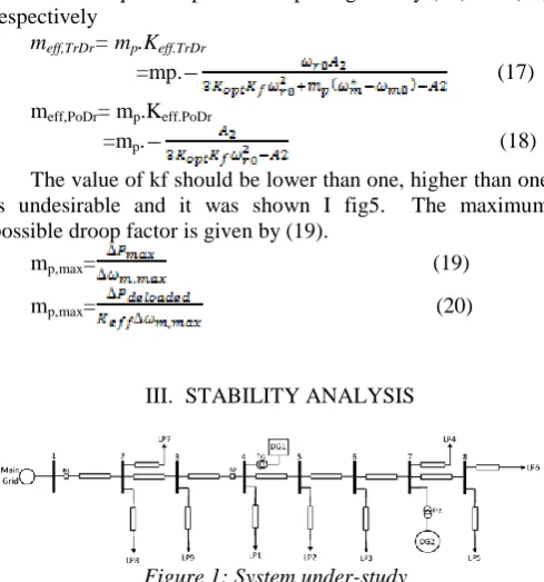
-0.02 0 0.02 0.04 0.06 time(sec) c h a n g e i n a c ti v e p o w e r( p .u ) Vw=14m/s Vw=9.5m/s
30 35 40 45 50 55
-0.02 0 0.02 0.04 0.06 time(sec) c h a n g e i n a c ti v e p o w e r( p .u ) Vw=14m/s Vw=9.5m/s
Figure 11: changes in active power output of stand-alone wind power generations with different wind speeds, Vw, whwn
droop is implemented in (a) torque and (b) power
30 35 40 45 50 55
-0.2 -0.1 0 0.1 0.2 time(sec) c h a n g e i n a c ti v e p o w e r( p .u ) Vw=14m/s Vw=9m/s (a)
30 35 40 45 50 55 -0.2 -0.1 0 0.1 0.2 time(sec) c h a n g e i n a c ti v e p o w e r( p .u ) Vw=14m/s Vw=9m/s (b)
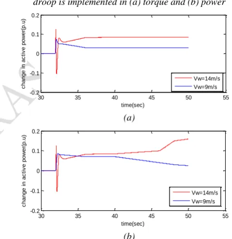
Figure 12: changes in reactive power output of stand-alone wind power generations with different wind speeds, Vw, when
droop is implemented in (a) torque and (b) power
Constant Wind Speed: One of the generators works at
Page 331 www.ijiras.com | Email: [email protected] as a result microgrid failure (fig 13). It is praiseworthy to
talk about that exactly the same case but with torque-droop remains stable.
Figure 13: frequency vs time when two stand-alone wind generators with identical wind speeds regulating the
microgrid frequency
Variable Wind Speed:
Similar Wind Speed Patterns: Both wind power
generators experience the similar wind speed pattern. The frequency regulation and power sharing responses was shown. Both DG units share the equal amount of the active power as they have same parameters shown in figs13 and 14.
30 35 40 45 50 55
0 0.2 0.4 0.6 0.8
time(sec)
ac
tiv
e
po
w
er
(p
.u
)
wind1 wind2
30 35 40 45 50 55
0 0.1 0.2 0.3 0.4
time(sec)
re
ac
tiv
e
po
w
er
(p
.u
)
wind2 wind1
Figure 14: wind (a) active power and (b) reactive power generation when two stand-alone wind generators with
identical wind speeds regulate microgrid frequency
Different Wind Speed Patterns: One DG unit with
different wind speed pattern is used while the other unit has the previous wind speed pattern .The power sharing performance was shown. Because of variable wind speed and dependency of the effective droop factor, a unit with higher wind speed generates more power which seems reasonably helpful.
30 35 40 45 50 55
10.5 11 11.5 12 12.5 13 13.5 14
time(sec)
w
in
d
s
p
e
e
d
(V
w
)(
m
/s
)
Figure 15: real windpattern
30 35 40 45 50 55
0 0.2 0.4 0.6 0.8 1
time(sec)
a
c
ti
v
e
p
o
w
e
r(
p
.u
)
wind2 wind1
(a)
30 35 40 45 50 55
0 0.05 0.1 0.15 0.2 0.25 0.3 0.35
time(sec)
re
a
c
ti
v
e
p
o
w
e
r(
p
.u
)
(b)
Figure 16: Wind (a) active power and (b) rective power generation responses
Compatibility Between Torque- and Power-Droops:
On comparing both droop methods even with the same parameters power sharing is not completely equal due to the impact of the effective droop factor(Fig.18 and 19).
Figure 17: Microgrid frequency response with different variable wind speed patterns
30 35 40 45 50 55
0 0.2 0.4 0.6 0.8 1
time(sec)
a
c
ti
v
e
p
o
w
e
r(
p
.u
)
(a)
(b)
Figure 18: wind (a) active power and (b) reactive power generation responses
Figure 19: Microgrid frequency response
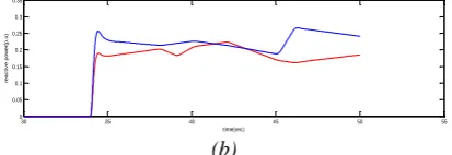
Frequency response for stand-alone wind power generation, active and reactive power response for partially deficient generation was compared with PI and FLC and better responses observed with FLC shown in Fig 20.
Page 332 www.ijiras.com | Email: [email protected] frequency response of microgrid was improved and it
was shown in Fig 21.
0 0.1 0.2 0.3 0.4 0.5 0.6 0.7 0.8 0.9 1 0
0.1 0.2 0.3 0.4 0.5 0.6 0.7 0.8
Active power vs time
time [s]
a
c
t
iv
e
p
o
w
e
r
(
p
.
u
)
With PI With FLC
(a)
0 0.1 0.2 0.3 0.4 0.5 0.6 0.7 0.8 0.9 1 0
0.05 0.1 0.15 0.2
Reactive power vs time
time [s]
r
e
a
c
t
iv
e
p
o
w
e
r
(
p
.
u
)
With PI With FLC
(b)
0 0.1 0.2 0.3 0.4 0.5 0.6 0.7 0.8 0.9 1
59 59.2 59.4 59.6 59.8 60 60.2 60.4 60.6
Change in Freqency in Hz
time [s]
Fr
e
q
u
e
n
c
y
(
H
z
)
With PI With FLC
(c)
Figure 20: wind (a) active power (b) reactive power and (c) frequency response for stand-alone wind power generation
0 0.1 0.2 0.3 0.4 0.5 0.6 0.7 0.8 0.9 1
0 0.1 0.2 0.3 0.4 0.5 0.6 0.7 0.8 0.9
Active power vs time
time [s]
P
[p
u
]
With PI With FLC
(a)
0 0.1 0.2 0.3 0.4 0.5 0.6 0.7 0.8 0.9 1
0 0.05 0.1 0.15 0.2 0.25
Reactive power vs time
time [s]
Q
[p
u
]
With PI With FLC
(b)
0 0.1 0.2 0.3 0.4 0.5 0.6 0.7 0.8 0.9 1
0 10 20 30 40 50 60 70
Change in Freqency in Hz
time [s]
F
rq
y
(H
z
)
With PI With FLC
(c)
Figure 21: wind (a) active power response, (b) reactive power response and (c) frequency response when PI and FLC used
IV. CONCLUSION
The effects of the torque- and power-droop implementation in DFIG units were analyzed. The variation of effective torque-droop could give in greater stability when compared to the power-droop method, it was shown by small-signal analysis. The positive effect of wind-droop on system frequency-stability, turbine governor and inverter droop functions showed. The wind power generation with autonomous frequency regulation has the capability to stabilize the frequency in an isolated microgrid was showed. Time-domain simulations verified for all results. Load sharing with different wind-droop methods and using Fuzzy Logic Controller were examined. And also for stand-alone wind power generation frequency response was improved by using FLC.
APPENDIX
Page 333 www.ijiras.com | Email: [email protected]
Generators: DG1, 2.5MVA DFIG,Kp1=114, Ki1=76,Kp2=3,Ki2=30,Tp=0.01,HDG1=3,Kopt=0.628,Kp,PLL= 250, Ki,PLL=100. DG2, 2.5MVA Synchronous Generator,
AVR Parameters:KA=400,TA=0.02, Non-reheat thermal
turbine : TCH=450ms, TG=0.08 s.
REFERENCES
[1] T. Bhattacharya and L. Umanand, ―Negative sequence compensation within fundamental positive sequence reference frame for a stiff microgrid generation in a wind power system using slip ring induction machine,‖ IET
Elect. Power Applicat., vol. 3, no. 6, pp. 520–530, 2009.
[2] Global Wind Energy Outlook, 2010 [Online]. Available: http://www.gwec.net[3] 20% Wind Energy by 2030: Increasing Wind Energy's Contribution to U.S. Electricity Supply. Washington, DC, USA, Jul. 2008, U. S. Department of Energy.
[3] G. Ramtharan, J. B. Ekanayake, and N. Jenkins, ―Frequency support from doubly fed induction generator wind turbines,‖ IET Renew. Power Gen., vol. 1, pp. 3–9, 2007.
[4] J. Morren, J. Pierik, and S. W. H. de Haan, ―Inertial response of variable speed wind turbines,‖ Elect. Power
Syst. Res., vol. 76, no. 11, pp.980–987, Jul. 2006.
[5] L. Wu and D. G. Infield, ―Towards an assessment of power system frequency support from wind plant— Modeling aggregate inertial response,‖ IEEE Trans.
Power Syst., to be published.
[6] M. F. M. Araniet al., ―Implementing virtual inertia in
DFIG-basedwind power generation,‖ IEEE Trans. Power
Syst., vol. 28, no. 2, pp.1373–1384, May 2013.
[7] A. Teninge, C. Jecu, D. Roye, S. Bacha, J. Duval, and R. Belhomme,―Contribution to frequency control through wind turbine inertial energy storage,‖ IET Renew. Power Gen., vol. 3, no. 3, pp. 358–370, Sep.2009.
[8] V. Courtecuisse, M. El-Mokadem, C. Saudemont, B. Robyns, and J. Deuse, ―Experiment of a wind generator participation to frequency control,‖ in Proc. Wind Power
to the Grid—EPE Wind Energy Chapter1st Seminar, Mar.
27–28, 2008.
[9] B. H. Chowdhury and H. T. Ma, ―Frequency regulation with wind power plants,‖ in Proc. IEEE Power and Energy Society General Meeting—Conversion and
Delivery of Electrical Energy in the 21stCentury, Jul. 20–
24, 2008.[11] R. G. de Almeida, E. D. Castronuovo, and J. A. Peas Lopes, ―Optimum generation control in wind parks when carrying out system operator requests,‖ IEEE
Trans. Power Syst., vol. 21, no. 2, pp. 718–725, May
2006.
[10]M. Shahabi, M. R. Haghifam, M. Mohamadian, and S. A. Nabavi-Niaki, ―Microgrid dynamic performance improvement using a doublyfed induction wind generator,‖ IEEE Trans Energy Convers., vol. 24,no. 1, pp. 137–145, Mar. 2009.
[11]K. Clark et al., Modeling of GE Wind Turbine-Generators for GridStudies, General Electric International, Tech. Rep., 2010.
[12]E. Loukarakiset al., ―Frequency control support and
participation methods provided by wind generation,‖ in