VFD based Speed Control of Three Phase
Induction Motor by PLC and SCADA
K. Prabakaran Dr. M. Kandasamy
Assistant Professor Associate Professor
Department of Electronics and Instrumentation Engineering Department of Electronics and Instrumentation Engineering Erode Sengunthar Engineering College, Thdupathi, India Erode Sengunthar Engineering College, Thdupathi, India
G. Revathy E. Sathish
Assistant Professor Assistant Professor
Department of Electronics and Instrumentation Engineering Department of Electronics and Instrumentation Engineering Erode Sengunthar Engineering College, Thdupathi, India Erode Sengunthar Engineering College, Thdupathi, India
Abstract
Three phase induction motors are mostly used AC motors in industry for various operations. Here the implementation of condition monitoring system for the 3-phase induction motor based on program able logic controller (PLC) & SCADA technology is described. Also the implementation of a hardware and software for speed control, direction control, parameter monitoring on SCADA screen is provided. Variable Frequency Drives (VFD) can also use to control the motor rotation direction and rotation speed of the three phase induction motor. All the required control and motor performance monitoring data will be taken to a personal computer by SCADA. The control of three phase induction motor is applied with VFD, PLC and monitored with SCADA. Keywords: Programmable Logic Controller, Supervisory Control and Data, Variable Frequency Drive
_______________________________________________________________________________________________________
I. INTRODUCTION
Automation has become the heart of industries. Industries are reaching new heights only because of advancement of automation technology. Plant automation is the necessity for the manufacturing industry to survive in the today’s globally competitive market. Growth of Industries leads to the reduction of manual controls day by day. One such contribution to the growing era is made through this paper. This paper is about controlling the speed of induction motor, which is most economical motor, using variable frequency drive (VFD) through programmable logic controller (PLC). VFD has been chosen specifically because they provide the advantages of energy savings, low motor starting current, reduction of thermal and mechanical stresses on motors and belts during starts, simple installation, high power factor and lower KVA. Variable frequency drives are generally required because in many applications it is not desired to run the motor at same speed all the time due to its surrounding circumstances.
The revolution per minute of the driven shaft need to be increased or decreased depending on load changes, application requirement or other circumstances. For example, a pump delivering cooling liquid supply may require peak load operation only for a requisite period of time and may require only much less amount during remaining time of the day. VFD will allow the speed of the pump to run at a lower rate in such case thereby enabling energy saving benefits. The Compact Logics PLC is used which is interfaced with the help of a software known as RS Logics 5000. The PLC has been connected to control and monitor a VFD which acts as a go-between the three phase induction motor and the PLC. The PLC processes the inputs according to the ladder logic programming and initiates corresponding output to the VFD. The VFD in turn once again processes the PLC input to it and accordingly controls the speed of three phase induction motor.
Ladder logic programming is carried out in RS Logics in the personal computer. A PLC based control system was set up comprising of an Allen Bradley Compact Logics PLC, an Allen Bradley Power Flex 4M variable frequency drive, a three phase induction motor in the Rockwell automation laboratory GLA University Mathura U.P. Speed control methods of three phase induction motors.
II. METHODOLOGY
To see current consumed by an induction motor on SCADA screen, we use CT which is connected in between motor and PLC. Output of CT is given to PLC through which value of current is shown on SCADA screen. VFD plays vital role in protecting motor from various faults like overload, overvoltage, over current, etc. Whenever faults occur, VFD indicates the same on its display. By referring code user will be able to find solution same within a short period of time. Here the system is set to sense motor parameters, to show them on SCADA screen also to control motor from SCADA. Once the parameters are sensed, PLC will decide whether measured parameters are within limit or not. If the parameter crosses the limit set by user, SCADA screen will give warning message on its screen. So at supervisory level, user will be able to see motor condition, its parameters whether they are crossing threshold or not. User also will be able to control motor.
In any electric motor, operation is based on simple electromagnetism. A current-carrying conductor generates a magnetic field; when this is then placed in an external magnetic field, it will experience a force proportional to the current in the conductor, and to the strength of the external magnetic field. As you are well aware of from playing with magnets as a kid, opposite (North and South) polarities attract, while like polarities (North and North, South and South) repel. The internal configuration of a DC motor is designed to harness the magnetic interaction between a current-carrying conductor and an external magnetic field to generate rotational motion.
Fig. 1: Block Diagram of Speed Control of Induction Motor by VFD
Steam Generator
A drum sub-critical natural circulation steam generator. All steel structures are fabricated with fully suspended structure. It has front and back wall opposed fired single furnace with balanced draft & dry slugging bottom ash hopper. The single reheat boiler gets its reheat steam temperature adjusted by modulation of gas dampers. The air pre heaters are arranged inside the boiler main frame. The coal feeding system, the boiler has eight sets of medium speed coal pulverizes with eight coal feeders and two primary air fans. The coal design or, specified coal at B-MCR output, seven sets of pulverizes are put into operation and the other one remains as standby. Six sets of pulverizes are required for 100% output.
Turbine
In thermal power plant, turbines play a major role in power generation. The turbine system is a rotary mechanical device that extracts energy from fluid flow and it generates the power.
Table - 1 Turbine Output Parameters
Parameter Rated Value Rated output 210MW
Speed 3000rpm Main steam temperature 537K
Condenser pressure 0.103 Ksc
Boiler
In thermal power plant, boilers play a major role in power generation. The boiler is an enclosed vessel that provides combustion heat which transfer water in to super-heated steam and pressure is then usable for power generation.
Table - 2 Boiler Parameters
Parameter Description
Type Subcritical, Natural circulation, opposed wall Firing, once reheating, single furnace, balanced Draft, Dry bottom boiler
Type of firing Front & rear Firing having 4 burner Elevations, Each elevation having 5 burners. Steam pressure at Super heater outlet 178.4503 ksc/17.5Mpa
Main Steam Temperature 541° C
Feed water Temperature Entering
Economizer 281° C
Feed Water Pressure 196.375 ksc
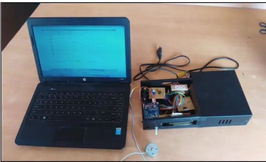
III. EXPERIMENTAL SETUP
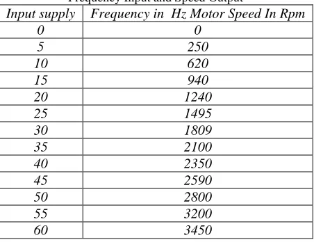
For the present work a real time control set up comprising of Allen-Bradley PLC, an Allen-Bradley Power Flex 4M Variable Frequency Drive, a three-phase induction motor driving a conveyor belt load controlled by ladder logic software installed in a personal computer. For various values of input supply frequencies, the corresponding values of motor speed in rpm were obtained as shown in Table 3. The experimental setup was shown in the Figure 3.
Table - 3
Frequency Input and Speed Output
Input supply Frequency in Hz Motor Speed In Rpm
0 0
5 250
10 620
15 940
20 1240
25 1495
30 1809
35 2100
40 2350
45 2590
50 2800
55 3200
Fig. 3: Speed control of motor using VFD
Programmable Logic Control
Programmable Logic Control also called programmable controllers or PLCs, are solid-state members of the computer family, using integrated circuits instead of electromechanical devices to implement control functions. They are capable of storing instructions, such as sequencing, timing, counting, arithmetic, data manipulation, and communication, to control industrial machines and processes.
Programmable controllers have many definitions. However, PLCs can be thought of in simple terms as industrial computers with specially designed architecture in both their central units (the PLC itself) and their interfacing circuitry to field devices (input/output connections to the real world).
Ladder Diagram and the PLC
The ladder diagram has and continues to be the traditional way of represent-in electrical sequences of operations. These diagrams represent the inter-connection of field devices in such a way that the activation or turning ON, of one device will turn ON another device according to a predetermined sequence of events.
Ladder Diagram
A thorough understanding of ladder diagram programming, including functional blocks, is extremely beneficial, even when using a PLC with IEC 1131 programming language capabilities. Because ladder diagrams are easy to use and implement, they provide a powerful programming tool when used in the IEC 1131 environment.
The main functions of a ladder diagram program are to control outputs and perform functional operations based on input conditions. Ladder diagrams use rungs to accomplish this control. The basic structure of a ladder rung In general, a rung consists of a set of input conditions and an output instruction at the end of the rung (represented by a coil symbol). The contact instructions for a rung may be referred to as input conditions, rung conditions, or the control logic. The ladder diagram for the speed control is shown in the Figure 4.
IV. RESULT AND DISCUSSION
Being an economical motor, three phase induction motors are used extensively in industries today. So, if speed of three phase induction motor can be controlled then wherever there is a use of three phase induction motor its speed can be controlled. Therefore, the control method discussed in this project can be applied to everywhere were three phase induction motor is used.
V. CONCLUSION
In this paper the three phase induction motor speed is controlled by using PLC and VFD. The motor is controlled with some automated systems and becomes the work very easier and the output is represented by using display. The man power is reduced and it reduces the type of work that changes manually. In future, the speed control becomes very simple and it is useful for various applications. The main advantage of PLC is to do the work automatically and complete the work and reduces the damage that occurs for the motor.
VI. APPENDIX
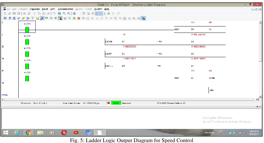
Fig. 5: Ladder Logic Output Diagram for Speed Control
REFERENCES
[1] Maria G. Ioannidis,(2013)“Initial Face of Automation - Programmable Logic Controller” International Journal of Advance Research In Science and Engineering, Vol. No. 2, Issue No. 2, pp.124-145.
[2] J. Ahir,(2008) “Design and implementation of PLC-based monitoring control system for three-phase induction motors fed by PWM supply” International Journal of Systems Applications, Engineering & Development, Issue 3, Volume 2, pages 128-135, pp.137-156.
[3] Y.Birbir,(2002)“Engineering fundamentals of multi-MW Variable Frequency Drives” Proceedings of the thirty-first Turbomachinery Symposium, pp. 177-194
[4] S.Da’na, (2012) “Using Variable Frequency Drives (VFD) to save energy and reduce emissions in newbuilds and existing ships” White Paper – ABB Marine and Cranes.pp.126-156.
[5] P.sun, (2007) Fundamentals of Electrical Drives, Second Edition, Narosa Publishing House, pp.234-245.
[6] J.Rasanen, (2015)"A Novel Method Of Induction Motor Speed Control Using PLC", International Journal for Research in Applied Science & Engineering Technology (IJRASET) , 3(2), pp.145-167.
[7] M.A.Badran, (2008) "Design and Implementation of PLC-Based Monitoring Control System for Three-Phase Induction Motors Fed by PWM Inverter", international journal of systems applications, engineering &development, pp.267-245.