O R I G I N A L R E S E A R C H
Rotating Magnetic Nanoparticle Clusters as
Microdevices for Drug Delivery
This article was published in the following Dove Press journal: International Journal of Nanomedicine
Alexander J Willis1
Sebastian P Pernal 2
Zachary A Gaertner 3
Sajani S Lakka1
Michael E Sabo4
Francis M Creighton4
Herbert H Engelhard 5
1Division of Hematology-Oncology,
Department of Medicine, The University of Illinois at Chicago, Chicago, IL, USA;
2Wayne State University, Detroit, MI,
USA;3Northwestern University, Chicago,
IL, USA;4Pulse Therapeutics, Inc, St.
Louis, MO, USA;5Departments of
Neurosurgery and Bioengineering, The University of Illinois at Chicago, Chicago, IL, USA
Background: Magnetic nanoparticles (MNPs) hold promise for enhancing delivery of therapeutic agents, either through direct binding or by functioning as miniature propellers.
Fluid-filled conduits and reservoirs within the body offer avenues for MNP-enhanced drug
delivery. MNP clusters can be rotated and moved across surfaces at clinically relevant distances in response to a rotating magnet. Limited data are available regarding issues affecting MNP delivery by this mechanism, such as adhesion to a cellular wall. Research reported here was initiated to better understand the fundamental principles important for successful implementation of rotational magnetic drug targeting (rMDT).
Methods: Translational movements of four different iron oxide MNPs were tested, in
response to rotation (3 Hz) of a neodymium–boron–iron permanent magnet. MNP clusters
moved along biomimetic channels of a custom-made acrylic tray, by surface walking. The effects of different distances and cellular coatings on MNP velocity were analyzed using videography. Dyes (as drug surrogates) and the drug etoposide were transported by rotating MNPs along channels over a 10 cm distance.
Results: MNP translational velocities could be predicted from magnetic separation times. Changes in distance or orientation from the magnet produced alterations in MNP velocities. Mean velocities of the fastest MNPs over HeLa, U251, U87, and E297 cells were 0.24 ± 0.02, 0.26 ± 0.02, 0.28 ± 0.01, and 0.18 ± 0.03 cm/sec, respectively. U138 cells showed marked MNP adherence and an 87.1% velocity reduc-tion at 5.5 cm along the channel. Dye delivery helped visualize the effects of MNPs as microdevices for drug delivery. Dye delivery by MNP clusters was 21.7 times faster than by diffusion. MNPs successfully accelerated etoposide delivery, with retention of chemotherapeutic effect.
Conclusion:The in vitro system described here facilitates side-by-side comparisons of drug delivery by rotating MNP clusters, on a human scale. Such microdevices have the potential for augmenting drug delivery in a variety of clinical settings, as proposed.
Keywords:etoposide, glioblastoma, iron oxide nanoparticles, in vitro model, lung cancer, magnetic drug targeting, nanodevice
Introduction
Nanoparticle technology offers ingenious strategies for improving the delivery
and targeting of therapeutic molecules for cancer and many other diseases.1–6
Magnetic nanoparticles (MNPs) may be used to enhance delivery of chemother-apeutic agents either through direct binding with the agent (which may or may not require a release mechanism), or by functioning as miniature devices
(“micro-motors”) for facilitating drug transport via convection or an extended
corona effect.7–12 Despite the promise of MNPs, successful clinical use of
Correspondence: Herbert H Engelhard The University of Illinois at Chicago,912 South Wood St., Chicago, IL 60612, USA Tel +1 312 996-4842
Email [email protected]
International Journal of Nanomedicine
Dove
press
open access to scientific and medical research
Open Access Full Text Article
International Journal of Nanomedicine downloaded from https://www.dovepress.com/ by 118.70.13.36 on 27-Aug-2020
magnetic drug targeting to date has been rare, under-scoring the need for improved in vitro models to bridge
the gap “from the bench to the bedside.”10–15 In
biolo-gical applications, individual MNPs tend to aggregate,
forming chains and/or clusters.16,17 The motion of such
structures (under ideal conditions) has been mathematically
described.18–27MNP aggregation produces changes in
mag-netic and physical properties, which may include an enhanced capacity for rotation and translational movement in response to a dynamic magneticfield.10,17,26–28
Most MNPs, and certainly MNP aggregates, would be expected to have limited capacity for moving through solid
tissue.29–31 However, fluid-filled conduits and reservoirs
within the body offer potential avenues for MNP-enhanced drug delivery.11,32–34Within these conduits, factors such as the nature of the transport medium, adhesion to the wall of the conduit, interaction with immune system cells, and distance and angle between the MNPs and the magneto-motive system, will have critical importance in determin-ing the success or failure of the intended therapies. Surprisingly, little data is publically available regarding
these specific issues, for systems that employ a rotating
magnet for MNP propulsion, especially over human-sized distances.10,11,35
Our group has been investigating a model system that
allows MNPs to be“remotely”propelled on a human scale
using a rotating permanent magnet.10,11,32,34 MNPs
syn-chronously counter-rotate in response to the magnet, act as microscopic stir rods and move by means of surface trac-tion down lanes of specially designed cell culture trays. This surface walking phenomenon has recently been
referred to as “magnetically enhanced diffusion (MED)”
and “magnetically induced rotation and translation
(MIRT).”10,11 Use of the parallel “biomimetic” lanes of
the tray can be used to facilitate comparisons between different experimental conditions. In two previous publica-tions, we initially described the basic magnet and acrylic
tray test configuration,10then used it to demonstrate how
tissue plasminogen activator (tPA) could be moved to the site of a blood clot in vitro using MNP clusters. In the primitive vascular model, the MNPs could be induced to
move even through whole blood.11 As the logical next
step, we now address the principles of the system as they pertain to cancer cells, and the delivery of a chemother-apeutic agent.
Here we report our new observations regarding: 1) the relative velocities of different types of rotating MNPs, 2) the effect of magnet position and tray orientation on MNP
velocity, 3) visualization of dye (as a surrogate for drug) movement in response to the MNP clusters, 4) movement of MNPs over monolayers of different cell types, and the resulting adherence to cells, and 5) MNP-facilitated deliv-ery of the chemotherapeutic drug etoposide, as determined by cellular viability testing. Etoposide was chosen because it has been commonly used, has a well-understood mechanism of action, and has been used in the
cerebrosp-inal fluid (CSF).32,36Our hypothesis was that MNP
clus-ters could be used as microdevices to deliver etoposide by
means of convection or bulkflow, in the absence of direct
etoposide conjugation to the MNPs.
Methods
Magnetic Nanoparticles (MNPs):
Synthesis, Size Determination, and
Magnetic Separation Time
Four different iron oxide MNPs were tested in initial studies.
These are referred to as Fe3O4-MNPs, Fe3O4@Au -MNPs,
Fe3O4@Au-GG -MNPs, and MBs. Synthesis of Fe3O4
-MNPs, Fe3O4@Au -MNPs, and Fe3O4@Au-GG -MNPs
was according to Venugopal et al.37 For this synthesis, all
chemicals were purchased from MilliporeSigma (Burlington, MA) with the exception of hydrogen tetrachloroaurate (III) hydrate, which was purchased from Alfa Aesar (Haverhill, MA). Magnetic microbeads (MBs) were provided by Pulse Therapeutics, Inc. (St. Louis, MO), and have recently been described.10,11,32MBs are ferrimagnetic, with single-crystal-line magnetite cores. The volume of MNP suspensions used in experiments described here was 20 µL (or 100 µL), from stock solutions of 25 mg/mL, unless otherwise noted.
For MNP synthesis, 3.46 g of iron (III) chloride
hexahydrate (FeCl3 • 6H2O) and 1.27 g of iron (II)
chloride (FeCl2 • 4H2O) were dissolved in 100 mL of
0.40 M hydrochloric acid aqueous solution (HClaq) to
make the iron stock solution. The molar concentrations of the two iron salts in the solution were 0.128 M iron (III) and 0.064 M iron (II), respectively. Three mL of 1 M TX-100 solution was added to 250 mL of 1 M aqueous sodium hydroxide (NaOH), then heated to 75°
C in a water bath. Twenty-five mL of the iron stock
solution was added dropwise into this solution under vigorous non-magnetic stirring. After complete addition of the stock solution, the stirring was continued for 20
mins at 75°C. The Fe3O4 magnetic cores obtained were
allowed to settle before magnetic separation, to remove the supernatant. These particles were then washed
International Journal of Nanomedicine downloaded from https://www.dovepress.com/ by 118.70.13.36 on 27-Aug-2020
multiple times with distilled water to remove excess surfactant, then resuspended in distilled water, and designated “Fe3O4”.
For coating these MNPs with gold, 1 g of gold (III)
chloride trihydrate was dissolved in 1 mL of dH2O,
while being protected from light, to create a
gold-coat-ing solution. Ten mL of the 25 mg/mL Fe3O4-MNP
solution was transferred to a 150 mL beaker, and 90
mL of dH2O was added for a total volume of 100 mL.
0.5 g of D (+) glucose was added to the iron core solution and sonicated for 15 mins before being placed in a 60°C water bath. Once the iron core solution reached 60°C, the gold-coating solution was added at a molar ratio of 1:2, then slowly stirred for 1 hr with non-magnetic stirring, protected from light. Gold-coated MNPs were transferred to a 50 mL Falcon tube (Corning, Corning, NY) and washed three times with
dH2O, with vortexing, sonication for 30 sec, and
mag-netic separation each time. The resulting “Fe3O4@Au”
particles were stored in dH2O at 25 mg/mL at room
temperature (RT).
For the production of“Fe3O4@Au-GG”particles, an
aqu-eous solution of gellan gum (PhytagelTM) was prepared by
slow addition of 5 mg of PhytagelTMto 90 mL of water while
heating using a magnetic stirring hotplate. Water was added until the solution volume reached 100 mL, and the pH was adjusted to 10 by dropwise addition of 1 M NaOH. This was then heated to 70°C while being stirred. After removing from
heat, 3 mL of Fe3O4@Au -MNPs was added dropwise to the
gellan gum solution while it was undergoing non-magnetic stirring. The solution was cooled to RT and stirred for an additional 1 hr, then washed and stored as described above.
MNP size determinations were performed using the Nanosight LM10, using the Nanosight NTA 3.0 software (Malvern, Malvern, UK). MNPs were prepared for analysis at a concentration of 1 mg/mL in PBS, then further diluted 1:100 to 10 ug/mL of MNPs. Directly prior to loading, the solution was sonicated using the Sonics Vibra-Cell (Sonics, Newton, CT). Nanoparticle motion was tracked for 30 sec in triplicate. For magnetic separation times, the Lifesep Series Biomagnetic Separator (Dexter Magnetic Technologies, Elk Grove Village, IL) was used, which was also used for MNP
washing. Twenty-five mg of each MNP was loaded into
separate 50 mL Falcon tubes suspended in 10 mL of phos-phate-buffered saline (PBS), which were then placed into the magnetic separator. The clearance of the MNPs was video recorded using an Olympus SZ-12 camera (Olympus Corp., Center Valley, PA). The videos were analyzed using
Quicktime (Apple Inc., Cupertino, CA). Separation time was measured in seconds. For CT and MRI imaging, evenly dispersed dilutions of MNPs were made in 5 mL of warm 2.5% agarose, and scanned in 12-well plates (Falcon) after refrigeration for 10 mins to harden the gel.
Rotating Permanent Magnet System
(Mini-MED) and Acrylic Trays
The dynamic magneticfield used in these studies was
gen-erated by a rotating permanent magnet system (“
mini-MED”) provided by Pulse Therapeutics, Inc. (St. Louis,
MO). This contains a neodymium-boron-iron permanent magnet (US patents 8,313,422, 8,308,628, and 8,529,428), which spins in one direction at 3 Hz, causing agglomerated MNPs to synchronously rotate and surface walk even when separated at a distance from the magnet. The mini-Med has recently been described in detail.10,11,32,34
Poly (methyl methacrylate) acrylic trays for testing the movement of MNPs by the mini-MED, were designed and produced as previously described.10,11,32,34These trays (US
patent applied for), were specifically designed to study the
magnetically induced rotation and translation (MIRT) of MNPs. MIRT trays are compatible with standard 96-well plate readers, as well as inverted microscopes, and therefore
can also be utilized for fluorescence or dye studies. Each
smooth, rounded lane in the straight lane tray is 1/8th inch (3.175 mm) wide. Here, a tray with a branching pattern was also used for dye studies. When used for tissue culture, trays were sterilized overnight using ethylene oxide, or with 100% ethanol and UV light.
Figure 1Ashows a CAD image used in the design of
the straight lane MIRT trays.Figure 1Bis a photograph of
a MIRT tray mounted on a plexiglass plate, over the mini-Med, in the offset above position (at a height of 20 cm).
Figure 1Cis a photograph of a portion of the tray, showing three of the eight lanes loaded with MBs (the most easily seen MNP) at their starting points, before the initiation of the rotation and translational movement resulting from starting the rotation of the magnet.
Standard Tray Positions and Video
Determination of MNP Velocity; Colored
Dye Analysis
A diagram illustrating the different tray positions used
for this paper is seen inFigure 2. The origins or starting
points for the MNPs (from the vantage point of this
figure), were always to the left. From this view, MNPs
International Journal of Nanomedicine downloaded from https://www.dovepress.com/ by 118.70.13.36 on 27-Aug-2020
moved to the right, whether above or below the magnet,
due to the influence of the mini-MED rotation. Use of
these standardized tray positions (designated “pull”,
“push”, “offset” and “offset below”) allowed
compari-sons to be made between MNP“runs,”and avoided
non-movement areas that might be created by the formation
A
C
B
Figure 1(A) CAD image used in the design of the“magnetically induced rotation and translation (MIRT)”trays. The lanes have rounded bottoms to simulate tubular conduits within the body. (B) Photograph of the MIRT tray mounted on a plexiglass plate, over the mini-Med magnet, in the offset above position (at a height of 20 cm). (C) Photograph of a portion of the tray, showing three lanes (or channels) loaded with MNPs at their starting points, before the initiation of the rotation and translational movement induced by activating the mini-MED. Use of the tray lanes can be used to facilitate side-by-side comparisons of different types of MNPs, MNP modifications, the addition of drugs, or alterations of the media and cells within the channels. The tray is compatible with a standard 96-well plate reader.
Figure 2Schematic illustrating the standardized MIRT tray positions used in this paper. This perspective is rotated 90 degrees to the left, from that shown inFigure 1B. The
figure is not drawn to scale: in actuality, the tray in the pull position would be relatively closer to the rotating magnet, if the starting positions for the MNPs were all 20 cm from the center of the magnet.
International Journal of Nanomedicine downloaded from https://www.dovepress.com/ by 118.70.13.36 on 27-Aug-2020
of magnetic cancellation nodes.38For some experiments, additional vertical stacking heights were added to the basic tray position.
Digital videos of MNPs being moved (in horizontal translation) by the mini-MED in the MIRT trays were made using an Olympus SZ-12 camera (Center Valley,
PA). An “average” velocity determination for MNPs
running down a lane was simply calculated from the MNP run time for the entire lane (distance: 10 cm). Velocity values in cm by cm analyses were calculated
using MATLAB’s Video Viewer application
(MathWorks, Natick, MA). As the leading edge of the MNP cluster passed each marked centimeter, the frame number was recorded. The difference in frames from cm to cm was divided by the frame rate (29.97 frames/ sec) to determine the time for that particular span. The distance (i.e. 1 cm) was divided by the time to deter-mine the velocity in cm increments. MNP acceleration was calculated by dividing the change in velocity read-ings over a given span, by the elapsed time.
In the cell-free system, MNP velocity was usually mea-sured using 1 mL per lane of PBS at RT. 20 µL of 25 mg/mL MNP solution was added to the starting points (i.e. origins) of the lanes of the tray. MNPs were pre-magnetized by placing the tray at the side of the magnet, which consolidated the MNPs at each lane origin. The tray was then mounted at the position of interest, so that the median of imaged lanes would be along the central plane of the magnet. MBs were chosen over other MNPs for more extensive studies, since they had the greatest velocity in response to the mini-MED (as detailed in the Results section below). This improved
velo-city profile (other factors being equal) would be expected to
convey an advantage in any future clinical setting. MB translation in the branched lane MIRT tray was studied using 8 mL of PBS, with 50 µL of 25 mg/mL MB solution being added to the starting point, again with pre-magnetiza-tion prior to the run.
Since most drugs are transparent, commercially available dyes (food coloring, trypan blue) were used to directly visualize the effects of MNP clusters on the movement of small molecules. Lanes of the straight lane tray were loaded with pre-mixed MNPs+yellow dye, versus 5 µL of yellow dye alone (which would indicate diffusion). Lanes were also loaded with 5 µL of blue dye placed 6 cm from the tray origin. Dye studies were
performed with the magnet in the “pull” position. For
branched lane studies, MNPs pre-mixed with yellow or blue dye were added to their respective lanes. Trypan
blue was obtained from Lonza (Basel, Switzerland). To study the effect of trypan blue (molecular weight
872.88) on MB aggregation, 5 μL of trypan blue was
added to 20 uL of 25 mg/mL of MBs, and the suspen-sion vortexed for 30 sec, before being placed on a slide for photography. The effect of trypan blue on MB velo-city was studied in the straight lane MIRT tray, using various tray positions.
Cell Culture, Staining, and Microscopy
Cell lines used in these experiments were obtained from the American Type Tissue Collection (Manassas, VA), along with
E297 (DOI 10.1097/00006123-200103000-00035) and
LKB1-KO (Jackson Laboratory, Bar Harbor, ME) cells. Cells were maintained using standard tissue culture technique at 37°
C in 5% CO2. HeLa cells were grown in MEM (Thermo
Fisher, Waltham, MA.), and H2122 cells were grown in RPMI 1640 (Thermo Fisher, Waltham, MA). All other cells were grown in DMEM (Thermo Fisher, Waltham, MA). Cells were supplemented with 10% FBS (Thermo Fisher, Waltham, MA.), 1% Pen/Strep solution (Corning Inc., Corning, NY.),
and 1% Ciprofloxacin (1 mg/mL) (Corning Inc.,
Corning, NY).
Cells were imaged either in 12-well culture plates, or MIRT trays, depending on the experiment. Phase-con-trast images were obtained with an inverted microscope
at 10× (Nikon Corp., Tokyo, Japan). Forfluorescence or
H&E staining, cells were washed with PBS before being
fixed in 4% paraformaldehyde for 10 mins at RT, and
washed again. Nuclei were stained in the MIRT tray by addition of 1 mL of Hoescht 33342 in PBS (1:1000 v/v; Sigma-Aldrich, St. Louis, MO) for 10 mins at 37°C. Cells in the MIRT tray were imaged using an EVOS
FL Auto 2 microscope (Fisher Scientific, Waltham,
MA). For scanning electron microscopy (SEM), samples were dehydrated using ethanol then hexamethyldisila-zane. Glass cover slips were adhered to aluminum mounts with double-sided sticky tape and sputter coated with 6.0 nm of Pt/Pd in a low-pressure argon atmo-sphere for conductivity. Surfaces were analyzed at the UIC Electron Microscopy Service facility (Research Resource Center). Morphology was examined using a Hitachi S-3000N Variable Pressure Scanning Electron
Microscope using secondary (SE) and backscatter
(BSE) detectors.
For cell adhesion studies, cell lines were grown in 6 well
plates to confluence, then treated with 1 mL of 10 µg/mL MBs
for 30 mins at 37°C, then washed three times with PBS to
International Journal of Nanomedicine downloaded from https://www.dovepress.com/ by 118.70.13.36 on 27-Aug-2020
eliminate non-adherent MBs. Images obtained by the inverted
microscope were converted into binary files, and analyzed
using ImageJ (National Institutes of Health) to quantify the relative number of MBs adhering to cells. For MIRT tray
studies of MB velocities over cells, 1 x 10⁵cells were seeded
into each lane of the sterilized MIRT tray, which were pre-coated with 1 mL of 0.1% gelatin and incubated at 37°C for 15
min. Cells were grown for 24–48 hrs (until confluent) before
further experimentation. Immediately prior to velocity deter-minations, the medium was replaced with 1 mL of PBS.
Evaluation of MB Delivery of Etoposide,
by MTT Assay and Trypan Blue Exclusion
Since MBs were the fastest MNP, experiments were designed to determine whether or not they could be used to deliver a chemotherapeutic drug (etoposide), in the absence of direct conjugation to the drug. Etoposide was purchased from Cayman Chemical Company (Ann Arbor, MI), and stored
at−20°C. Etoposide dilutions were made from a stock
solu-tion of 1 mg/mL in DMSO. The direct cytotoxic effects of different concentrations of etoposide (ranging from 1 to 100 µM) were studied prior to MB testing. Baseline (static) studies were performed in 12-well culture plates, with direct treatment of cells (U138 and H2122) in monolayer culture, using 1) etoposide alone, 2) MBs alone, or 3) a combination of MBs with etoposide, in comparison to untreated control cells. In these static studies, no magnet was used.
Standard MTT assays were performed in 12-well
plates, as previously described.39 Cells were seeded at
a density of 105cells per well and grown for 24 hrs then
treated for 24 hrs. Thiazolyl blue tetrazolium bromide powder (MilliporeSigma, Burlington, MA) was dis-solved in 1X PBS at a concentration of 5 mg/mL to make the MTT working solution, which was diluted in media at 10% v/v. After cells had grown for 24 hrs, media was aspirated, cells were gently washed 3 times
with 200μL PBS, fresh media was added, and a 100 μL
treatment volume was applied. After incubation at 37°C
in 5% CO2for 24 hrs, media was aspirated, MTT-media
was added, and cells were incubated at 37°C (5% CO2)
for 4 hrs. The MTT-media was aspirated, DMSO was added, and cells were incubated at 37°C for 30 mins. The resulting solution was transferred to 96-well plates in triplicate and read with a SPECTRAmax 340PC (Molecular Devices, San Jose, CA) at 590 nm in triplicate.
Translational (i.e. dynamic) experiments were then performed to determine whether or not etoposide could be transported 10 cm down the length of the MIRT tray by MB clusters in response to the mini-MED. The straight lane MIRT tray in the 20 cm pull position was used. Sixty
μL of MBs alone and 60 µL of MBs plus 100μM
etopo-side were loaded at the starting points of the tray. The
mini-MED was turned on (“activated”) for 5 mins to
ensure that all MBs had traveled the complete distance
of the tray. Four hundredμL of MB solution was removed
from the end of each lane and transferred to an Eppendorf
tube. One hundredμL of this solution was applied to wells
of a pre-seeded 12-well culture tray (U138 and H2122; 105
cells/well, 24 hrs), in triplicate. After a treatment time of 2
hrs at 37°C in 5% CO2, the supernatant (including any
dead cells) was transferred into a 15 mL Falcon tube (Corning, Inc., Corning, NY) and 1 mL of media was added per well in order to harvest the remaining cells. Cells were detached with gentle use of a cell scraper and added to the 15 mL tube, which was centrifuged at 1800 rpm for 5 mins. Cell pellets were resuspended in 1 mL of
media. One hundred μL of cell suspension was added to
400μL of trypan blue. TenμL of trypan blue cell
suspen-sion was then transferred to a hemocytometer, and live and dead cells were counted, with counts being performed 5 times per group.
Data Display and Tests of Statistical
Signi
fi
cance
Data (e.g. the velocity curves) are expressed as mean and standard deviation (mean ± SEM) with n values as given
in the text and/orfigure legends. Statistical significance for
the velocity and absorbance experiments was determined using two-factor ANOVA with replication. A value of
p< 0.05 was considered to be statistically significant.
Results
Comparison of MNP Types: Magnetic
Separation Times, Translational Velocities,
and Particle Sizes
In initial studies, the magnetic separation times for the four different MNPs in PBS were determined using the
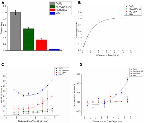
biomag-netic separator. Results are shown inFigure 3A. MBs had
the fastest clearing time (approximately 5 sec) due to their greater magnetic dipole moment. The movement of the four types of MNPs in the MIRT tray in response to the rotating permanent magnet (mini-MED) was then studied. MNPs
International Journal of Nanomedicine downloaded from https://www.dovepress.com/ by 118.70.13.36 on 27-Aug-2020
form clusters in response to a magneticfield. MNP clusters counter-rotate and act as microscopic stir rods, in response
to a rotating magneticfield, resulting in the surface-walking
phenomenon at a distance from the magnet. Here, PBS was used as the transport media, and the pull position for the tray
was used (as illustrated inFigure 2), with a starting distance
of 20 cm from the magnet center. Not unexpectedly, the MBs moved the fastest in this situation as well, traversing a centimeter in approximately 2 seconds. Average velocities were plotted against the inverse of the magnetic separation
times for the four MNPs, as shown in Figure 3B.
Videography and digital analysis allowed for accurate
quan-tification of MNP velocities, cm by cm, as they moved
down the lanes of the MIRT tray.
Use of the parallel lanes was used to facilitate side-by-side comparisons of MNP translational velocities and cluster dispersion, according to particle type/coating. A plot of MIRT tray velocity versus distance from the tray origin for the different formulations, can be seen (for the
pull position) in Figure 3C. With this tray position,
MNPs accelerate due to the addition of the force of attraction to the permanent magnet, to the velocity pro-duced by cluster rotation and surface traction, as the MNPs approach the mini-MED. This is shown in
Figure 3D, which is a plot of particle acceleration as a function of distance down the tray.
MNP sizes were determined using the Nanosight
LM10 instrument and NTA 3.0 software. Mean
Figure 3(A) Comparison of the magnetic separation times of the four different MNPs (n=3). (B) Average MIRT tray velocity (pull position) plotted as a function of the inverse of magnetic separation (clearance) time. The MBs separate most quickly and move the fastest in the MIRT tray. (C) MNP velocities plotted centimeter by centimeter as they move down the tray, in the pull position, showing the differences according to particle type (n≥3). (D) MNP acceleration, in the pull position, showing the greater acceleration as particles approach the magnet as demonstrated by the MBs.
International Journal of Nanomedicine downloaded from https://www.dovepress.com/ by 118.70.13.36 on 27-Aug-2020
diameters for Fe3O4, Fe3O4@Au, and Fe3O4@Au-GG –
MNPs were 95.4 ± 20.0, 105.9 ± 15.1 and 109.2 ± 9.7 nm, respectively, which indicated that the sequential coating process with gold and then gellan gum was successful and increased the particle diameter. Solitary MBs have a mean diameter of 60 nm and are prepared
differently.10,11,32 Translational velocity was therefore
not just a function of particle core size. Based on these results, the MBs were used for further studies, due to their greater velocities and capacity for move-ment at greater distances from the mini-MED. Pre-mag-netizing the MBs (by exposing them to the magnet prior to initiating magnet rotation) increased MB velocities, and was used as part of the standard procedure for subsequent experiments. MBs can be visualized radio-graphically, by x-ray, CT scan, and MRI. CT and MR images of MB dilutions (as indicated) are seen in
Figure 4A and B. MRI, as expected, was found to be
far more sensitive for MB detection than CT, especially when using T2-weighted or ultrafast gradient-echo imaging.
Effect of MIRT Tray Position on MB
Velocity
Changing the position (and/or distance) of the MIRT tray relative to the mini-MED changed the velocities of the MNPs - an important consideration (of course) when considering moving from in vitro to animal or especially human use. In data presented here, all tray positions were centered in the plane of the rotating
magnetic field (as shown in Figure 2). Figure 4C
shows average MB velocities in the four key positions: pull, push, offset and offset below. The standard starting point (origin) from the magnet center was 20 cm in all positions shown. The pull position produced the greatest average velocity. MNPs placed in a tray directly above the magnet (not offset) demonstrated complex patterns
of motion, due to the combination of “pull”and “push”
effects.
Figure 4D shows MB velocities centimeter by
cen-timeter, as they move down the lanes of the MIRT tray. MB clusters seem to oscillate, with some expansion and
C
B
A
D
E
0 2 4 6 8 10
0.0 0.1 0.2 0.3 0.4 0.5 0.6 0.7
0.8 PullPush
Offset Offset (Below)
)c
es/
mc
(
yti
col
e
V
Distance from Tray Origin (cm)
2 3 4 5 6 7 8 9 10
-0.10 -0.05 0.00 0.05 0.10
0.15 Pull
Push Offset Offset (Below)
ce
s/
mc
(
noi
ta
rel
ec
c
A
2)
Distance from Tray Origin (cm)
0 2 4 6 8 10
0.0 0.1 0.2 0.3 0.4 0.5 0.6
20cm 25cm 30cm
)c
es/
mc
(
s
B
Mf
o
yti
col
e
V
Distance from Tray Origin (cm)
F
Figure 4(A) CT images of 0–500 µL of agarose-embedded MBs in tissue culture wells. (B) Ultrafast gradient-echo MR images of agarose-embedded MBs, with concentrations as indicated. Here, use of adjacent wells was avoided, in order to avoid imaging artifacts. (C) Average MB velocity according to tray position (n>3). MBs moved fastest in the pull position. (D) MB velocity according to tray position, centimeter by centimeter, as determined by video analysis. In the pull position, they accelerate as they approach the magnet; in the push position, velocity falls off. (E) MB acceleration according to tray position, which similarly shows the greatest acceleration close to the magnet, and acceleration decreasing in the push position farther away from the magnet. (F) Velocities of MBs in the offset above position, with the tray at three different heights above the mini-MED (n=9). As expected, increasing the distance from the rotating magnet resulted in decreased velocities of the particles.
International Journal of Nanomedicine downloaded from https://www.dovepress.com/ by 118.70.13.36 on 27-Aug-2020
contraction as they moved down the lane. MB velocity increases in the pull position at the end of the lane, since particles are approaching the magnet. This was
confirmed in the acceleration plot, as seen in
Figure 4E. Determinations were made to see how the
amount of MBs used (i.e. aliquot size) affected their velocity, and whether lane position (e.g. lane 1 versus lane 3) was a factor in MB velocity, such as due to lack
of homogeneity in the magnetic field. These results are
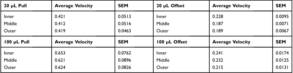
shown in Table 1. While the effect of lane position on
MB velocity was not found to be statistically significant,
larger MB aliquots (100 µL in comparison to 20 µL) did indeed have greater velocities, especially in the pull position. Increasing the distance of the tray from the min-MED resulted in decreased velocities as expected,
as seen in Figure 4F, for the offset (above) position.
Dye Diffusion versus Magnetically
Enhanced Dye Delivery
In order to model the effect of MBs on delivering a drug to a target area (through a conduit), studies with yellow and blue
dyes were performed. Most drugs are transparent, butfl
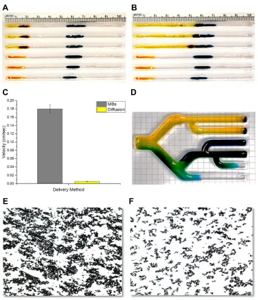
uores-cent drugs, or tagged therapeutic molecules, can also be studied in this fashion since the MIRT tray is compatible with standard 96-well plate readers. MBs (acting in response to the rotating magnet) were found to greatly accelerate dye delivery, when compared to diffusion alone. An example of this effect is
illustrated in Figure 5A and B, for a cell-free system. Six
lanes of the straight lane MIRT tray are shown, each of which contains yellow dye (representing drug) and blue dye
(representing the target).Figure 5Ais a photograph of the tray
immediately after loading and initiating MB rotation with the
mini-MED.Figure 5Bshows the dispersion of the dye 30 sec
later, when the MBs contact the target region. Successful dye
delivery was confirmed once green coloring appeared.
The average velocity of the yellow dye as propelled by the MBs (0.18 + 0.01 cm/sec), versus by diffusion alone (0.005 +
0.0006 cm/sec), is graphed inFigure 5C. ANOVA two-factor
analysis with replication showed that these values are
statisti-cally different, with p≪0.05. In both situations, dye does
become diluted with movement down the lanes of the tray. MBs were able to transport dye (as a drug surrogate) in a
branched lane tray as well, as illustrated inFigure 5D. Dye
delivery could therefore be used to visualize the effect of MNPs as microdevices for drug delivery (i.e. by convection
or bulk flow), in the absence of direct conjugation to the
particles. MB-facilitated movement of trypan blue dye also studied. Trypan blue, which is negatively charged, inhibited the formation of MB aggregates when vortexed with MBs, as
seen inFigure 5EandF. Combining MBs with trypan blue, did
slow translational velocity somewhat, depending on tray posi-tion. Individual dyes were therefore found to respond differ-ently in the model system, according to factors such as size, concentration, and surface charge, and the same would be anticipated for different drugs.
Movement of MBs Over Cellular
Monolayers and Adherence of MBs to
Cells
Interaction of MBs with cells cultured in monolayers was then studied, for several different cell lines, including HeLa (cervi-cal cancer), human glioblastoma lines, and LKB1-KO.
Different MB volumes, and cellular confluence percentages,
were tested. MBs placed at the edge of a monolayer of cells in a standard 6-well plate, then exposed to the action of the
mini-MED, tended to fan out to both sides, as seen inFigure 6A.
Effects resulting from proximity to the side of the well, and at
thefluid meniscus, were also observed. MBs were seen to
adhere differently to different types of cells forming a
con-fluent monolayer. Phase-contrast microphotographs, and
images of cells stained with hematoxylin and eosin, are
Table 1Effect of Lane Position (Pull vs Offset Above) and Aliquot Size (20 vs 100 µL) on Average Velocity of MB Clusters
20 µL Pull Average Velocity SEM 20 µL Offset Average Velocity SEM
Inner 0.421 0.0513 Inner 0.228 0.0095
Middle 0.412 0.0516 Middle 0.187 0.0071
Outer 0.419 0.0463 Outer 0.189 0.0067
100 µL Pull Average Velocity SEM 100 µL Offset Average Velocity SEM
Inner 0.653 0.0762 Inner 0.241 0.0174
Middle 0.621 0.0896 Middle 0.232 0.0125
Outer 0.624 0.0826 Outer 0.215 0.0131
International Journal of Nanomedicine downloaded from https://www.dovepress.com/ by 118.70.13.36 on 27-Aug-2020
shown inFigure 6BandC, respectively. A scanning electron microscope (SEM) image of an MNP cluster on a
glioblas-toma cell is seen inFigure 6D. Fe3O4@Au-MNPs were less
toxic than Fe3O4-MNPs, at a treatment time of 24 hrs. No
evidence was observed of any significant cellular toxicity
resulting from exposure to MBs. Image J was used to quantify MB adhesion to the cancer cells after cell washes, with results
shown inFigure 6E. MBs were seen to be more adherent to
live cell monolayers than to paraformaldehyde-fixed cells, and
more adherent (in general) to cancer cells than non-neoplastic
cells.Figure 6Eshows MB adherence to live andfixed glioma
cells, versus cultured non-neoplastic astrocytes.
Cells were then grown in the lanes of the MIRT tray, in order to channel the translational movement produced by the mini-MED, as could be utilized in order to transport MNPs within physiologic conduits inside the body (such as blood vessels, the spinal subarachnoid space, ureters, lymphatics,
etc.) Our data on vascular cells have been recently reported.11
Cells were found to grow better in trays milled from acrylic, than in trays 3D printed in VeroClear. Bits of the poly (methyl
Figure 5(AandB) A comparison of dye diffusion versus magnetically enhanced dye delivery, as demonstrated in the MIRT tray. (A) Positions of MBs with dye (top three lanes) and dye samples alone (bottom three lanes) at the time of mini-MED activation, with blue dye targets in the central portion of the tray. (B) Positions 30 sec later, when the MBs bring the yellow dye into contact with the blue target region (top three lanes), versus dye diffusion proceeding without MBs (bottom three lanes). (C) Bar graph showing a comparison of the velocities of MB-induced dye delivery versus movement by diffusion alone (n=3). (D) Photograph showing dye movement in response to MBs in a branched tray system, after 15 mins of mini-MED activation. MBs drag blue and yellow dyes (as drug surrogates) along with them, which then co-mingle to form green. (E
andF) Effect of trypan blue dye on MB dispersion. (E) Photomicrograph of MBs in PBS. (F) Photomicrograph of MBs in PBS with addition of trypan blue, showing the resulting increase in particle dispersion (10× magnification).
International Journal of Nanomedicine downloaded from https://www.dovepress.com/ by 118.70.13.36 on 27-Aug-2020
methacrylate) acrylic were found to have less of a growth-inhibitory effect on U87 cells at 48 hrs, than similar pieces of VeroClear. Cells could be successfully grown in MIRT trays for up to 120 hrs, depending on the type of cell, and number of cells initially seeded.
Dynamic experiments were performed, with MBs trans-ported down the lanes of the MIRT tray by the mini-MED, over cellular monolayers of a variety of cell types. This was to determine whether or not MB velocity would be affected differently, by different types of cells coating the lanes, and
to determine whether or not there would be particle attrition due to adhesion of particles to the walls of the lanes. A clinically relevant scenario, for instance, might be that of clusters of cancer cells seeded within the spinal subarachnoid space, which might be more adherent to drug-laden MNP clusters. Of the cell lines tested, MIRT lane velocity was the least for U138 and E297 cells, which corresponded to their high MB adhesion rates. A photomicrograph of Hoechst 33342-stained U138 cells in a lane of the MIRT tray after
MBs have passed, is shown inFigure 7A. Cells are blurry at
A
B
C
D
E
Figure 6(A) Photograph showing the pattern of MBs as they fan out across a cellular monolayer. (B) Photomicrograph showing the adherence of MBs to live cancer cells, as seen by phase-contrast microscopy. The MB clusters are seen here as highly refractile (white) particles. (C) Photomicrograph showing the adherence of MBs tofixed cancer cells (E297, human glioblastoma), after H&E staining. (D) A scanning electron microscope (SEM) image of an MNP cluster on a glioblastoma cell (arrow). (E) Bar graph indicating the relative adherence of MBs to different types of cells, unfixed (blue) versusfixed with paraformaldehyde (gray), as quantified using ImageJ (LKB1, E297 and U87 are glioma cells; Astrocytes are not neoplastic).
International Journal of Nanomedicine downloaded from https://www.dovepress.com/ by 118.70.13.36 on 27-Aug-2020
the top of the photo, due to the curvature of the tray lane. Residual MBs can be seen adhering to the cells, as indicated in white using this technique.
The MB velocities over cellular monolayers (centimeter by
centimeter) of different cell types are shown inFigure 7B. For
these studies, the above offset position was used. The average velocities of MBs over HeLa, U251, U87, and E297 cells were 0.24 + 0.02 cm/sec, 0.26 + 0.02 cm/sec, 0.28 + 0.01 cm/sec, and 0.18 + 0.03 cm/sec, respectively. The attrition of MNP clusters with movement, due to MNP adhesion to the lanes, was also greater with some cells, such as U138 cells. MB
movement over certain cell lines was found to be significantly
slower (and with higher cluster dispersion), likely indicating
their relative“stickiness”. U138 (human glioblastoma cells)
for example, showed marked MNP adherence, and an 87.1% reduction in velocity (in comparison with U87 cells) at a
distance of 5.5 cm along the channel. This difference was
found to be statistically significant by ANOVA, with
p≪0.05. It would be advantageous to be able to quantify
(and exploit) such adherence to cancer cells in human applica-tions of magnetic drug targeting.
Etoposide Cytotoxicity Testing and MB
Drug Transport Over Human-Sized
Distances
U138 cells in wells were treated with various concentra-tions of the classic chemotherapeutic agent, etoposide, in order to establish parameters for assessing cytotoxic activ-ity. Direct treatment with 100 µM etoposide for 24 hrs (without employing the magnet) was found to decrease cellular viability to 23.0 + 0.4%, as studied by MTT
assay. These results are shown inFigure 8A.
Etoposide was added to lanes at the starting points of the MIRT tray, with 60 µL aliquots of MBs. Control lanes were also employed, which used MBs alone. MBs were remotely moved down the length of the tray (10 cm) in PBS using the mini-MED, with the tray positioned at 20 cm in the pull position. After 5 mins, MBs (with associated media) were removed from the ends of the lanes and used to treat U138 and H2122 cells for 2 hrs. Cells were analyzed for cytotoxic effect using trypan blue
exclusion. Results are shown inFigure 8BandC, for U138
(human glioblastoma) and H2122 (human lung adenocar-cinoma) cells, respectively. The cytotoxic effect of etopo-side was retained after being delivered by MBs, and this
result was found to be statistically significant (p < 0.05).
Such an effect could not have been achieved by means of drug diffusion (with associated dilution) alone, therefore indicating the successful delivery of drug by the rotating MNP clusters.
Discussion
Data reported here show that: 1) The translational velo-cities of MNP clusters moving down the lanes of the MIRT tray (in response to the rotating magnet) can be roughly predicted from their clearance times in the mag-netic separator; 2) Changes in the position of (or distance from) the rotating magnet predictably change the velocity of the MNPs, as does the size (i.e. mass) of the MNP aliquot; 3) Dye delivery can be used to visualize the effect of MNPs as microdevices for drug delivery; 4) MB clus-ters directed down MIRT tray channels lined with cells
Figure 7(A) Photomicrograph of residual (adherent) MBs in a MIRT lane contain-ing U138 (human glioblastoma) cells. Cell nuclei were stained with Hoechst 33342. MBs clusters appear white on this image. Cells are blurry at the top of the photo, due to the curvature of the tray lane. (B) Graph showing the effect of cell type on MB velocity in the MIRT tray, in the offset above position. Different cell types were found to have different effects on the velocity and dispersion of the MB clusters.
International Journal of Nanomedicine downloaded from https://www.dovepress.com/ by 118.70.13.36 on 27-Aug-2020
exhibit varying velocities and degrees of wall adherence, depending on cell type; and 5) MB clusters can be used to enhance the delivery of the chemotherapeutic agent
etopo-side, across the “mesoscale” distance of 10 cm.
Non-functionalized iron oxide MNPs were studied as convec-tive microdevices, and coating with gold and gellan gum did change the observed velocities. MBs were chosen over the other MNPs for more extensive studies, since they demonstrated the greatest velocity in response to the
mini-MED. An improved velocity profile (other factors
being equal) would be expected to convey an advantage in a clinical setting in which drug delivery is being augmented.
Admittedly, the in vitro model and test conditions used here are rudimentary and do poor justice to actual physiolo-gical conditions. Yet, the principles such experiments estab-lish set the stage for achieving a more sophisticated understanding of MNP movement on a human scale, and ultimately for possible therapeutic use. Modeling of more complex conduit branching patterns in three dimensions would certainly be useful for predicting MNP movement and drug delivery within a variety of human structures and would add complexity in exponential fashion. With larger, more powerful magnets, the distance separating the magnet and MNPs could be greater, and with higher rotational speeds, the surface walking of the particles could potentially be faster. In the results reported here, MNP clusters
func-tioned as medical devices (or“nanobots”) enhancing fluid
transport for drug delivery11,40,41and did not require direct drug conjugation or a mechanism for triggering drug release. When MNPs enter an environment containing cells, they adsorb biomolecules and form a corona, assuming a biological identity which is distinct from their synthetic identity.42–47The
composition of the bio-corona will depend on the specific
environment in which the particles are used, and can include solutes, lipids, protein, and other molecules.1,42,48–50Surface charge and corona formation can be altered by nanoparticle coatings, which in turn affect nanoparticle adherence to (and uptake by) cells.13,51,52 Different types of cells have been
studied for this effect including macrophages, fibroblasts,
osteoblasts, and HeLa, neuroblastoma and ovarian cancer cells.44,51,53–59Since corona formation may affect MNP tar-geting and drug delivery, this phenomenon provides another rationale for laboratory modeling (such as our own), prior to resource-intense in vivo studies. The MBs studied here have been reported to rotate and display translational movement
through serum and even blood,10,11fluid environments shown
to generate a corona. Use of the MIRT tray and mini-Med for primitive modeling of blood vessels, for analysis of tPA
deliv-ery to a blood clot, has recently been reported.11
Considering MNP modeling relevant to cancer, studies have shown that a variety of chemotherapeutic drugs can be
0 20 40 60 80 100
)
%(
ytil
ib
ai
Vll
e
C
Negative Ctrl 1 uM Etop 10 uM Etop 100 uM Etop
0 20 40 60 80 100 120
*
)
%(
ytil
ib
ai
Vll
e
C
Ctrl MBs Alone MBs+Etop
0 20 40 60 80 100 120
*
)
%(
ytil
ib
ai
Vll
e
C
Ctrl MBs Alone MBs+Etop
A
B
C
Figure 8 Etoposide cytotoxicity in static vs dynamic (MIRT tray) studies. (A) Viability analysis of etoposide treatment of U138 cells in a 12-well plate, as determined by MTT assay. 1 µM, 10 µM, and 100 µM etoposide were used and compared to 10 µL of DMSO (10 µM volume equivalent) alone per well (n=3). (B
andC) Trypan blue cell viability analyses after MBs were used to move etoposide down the lanes of the MIRT tray. (B) U138 (human glioblastoma) cells. (C) H2122 (human lung adenocarcinoma) cells. MBs successfully transported etoposide by convection/bulkflow (5 mins) to allow cancer cell killing as shown by this assay (n = 3; *p < 0.05).
International Journal of Nanomedicine downloaded from https://www.dovepress.com/ by 118.70.13.36 on 27-Aug-2020
bound to, and transported by MNPs.60–63MNP-chemotherapy constructs have demonstrated growth-inhibitory effects in vitro and in animal studies for many types of cancer cells, including glioblastoma.2,64-66Ingenious larger nanostructures
(“micro-robots”) which can be actuated by external magnetic
fields have also been described, with the goal of targeting drug
delivery.67–70These may or may not contain iron, or utilize a
tumbling motion.67,71Few reports have described the use of
unbound MNP clusters (also referred to as“aggregates”or,
more accurately“agglomerates”) as microdevices for
deliver-ing therapeutic agents at human-sized distances.11,33,72 As
with solitary nanoparticle-drug conjugates, multiple strategies are envisioned that would allow MNP clusters to disperse and
release drug at their target site.73 Tumors demonstrate an
“enhanced permeation and retention effect”, and individual
tumor cells, as well, are likely to demonstrate heightened
nonspecific binding and uptake of drugs and nanoparticles
due to their greater metabolic needs.74,75In the CNS, reports have demonstrated that magnetic particles can be moved within the CSF-containing conduit of the spinal subarachnoid
space.76–78 These studies have employed either fixed
(non-rotating) permanent magnets or static electromagneticfields.
While the surface walking phenomenon of magnetic
parti-cles in response to a rotating or oscillating magneticfield has
long been recognized, its potential clinical application for drug delivery has recently gained new appreciation.3,10,11,40,41The main advantages of using a rotating permanent magnet as a magneto-motive unit (over that of a static or oscillating
elec-tromagneticfield) are that: 1) it may be able to induce MNP
cluster movement at a greater distance; and 2) it can act unilaterally, i.e. it does not have to surround the target region.40 Few animal studies have yet been reported which utilize this
rotational mechanism.41,79Additional data are needed
regard-ing many important and fundamental considerations of the
variables influencing rotating MNP clusters as devices for
drug delivery. While the human condition entails even more complexity, a list of factors that could affect rotational mag-netic drug targeting (rMDT)–just in vitro–is given inTable 2.
Clinical Applications of Rotational
Magnetic Drug Targeting
MNP clusters induce drug movement in the absence of direct drug conjugation to the MNP itself. They are envisioned as acting as implantable micro-motors, which may have a capa-city for being (at least partially) removed, due to their mobile,
Table 2Variables Influencing Rotational Magnetic Drug Targeting (rMDT) in vitro (Factors May Be Redundant, Overlap, Interact)
A. MNP / Cluster B. Tray / Lane
MNP type / size /
composition / heterogeneity
Composition
MNP magnetization / zeta potential
Lane width / radius
MNP charge / coating Smoothness / irregularity / pitting
Prior magnetic exposure Electrostatic effects / charge
Composition of corona Elasticity /flexibility
Particle mixture / ratios Erosion / friability
Aggregate / cluster size Coating
Cluster stability / disassembly
Branching / curvature
Cluster cohesion Wall shear / margination
Torque / traction Wall adherence
Cluster adherence / interactions
Barrier phenomena (e.g. encountering target cell cluster or clot) / reflection
Coefficients of friction: rotational
Coefficients of friction: static, dynamic
Wave phenomena / energy dissipation
C. Media D. Cellular lining
pH / temperature Type / size
Viscosity / cavitation Density / % confluence
Composition (protein, lipid, etc.)
Surface characteristics / waviness
Heterogeneity Metabolic / endocytotic activity
Volume / depth / meniscus Lane adherence
Cells suspended in media (e.g. RBCs, immune cells)
Cluster adherence
Bulkfluidflow / axial pulsations
Cellular mixture (e.g. endothelial plus cancer)
Webbing / matrix / scaffolds Ciliation
E. Magnetic source F. Drug / Miscellaneous
Distance Drug type / size
Position / rotation (3D) Drug charge / solubility / lipophilicity
(Continued)
International Journal of Nanomedicine downloaded from https://www.dovepress.com/ by 118.70.13.36 on 27-Aug-2020
magnetic nature. Accordingly, the FDA approval process may be different from that of a drug–nanoparticle conjugate.73,75 The advantage of magnetic drug targeting (MDT) lies in its potential ability to control the concentration and distribution of drug within a desired target region. This is usually accom-plished with external driving magnets, and is expected to
minimize toxicity in untargeted tissue.29,80 Maximal pull or
push forces can be used within the body to direct MNPs to
precise locations, even against currents.38,80To date, human
trials of MDT have been restricted to a focusing depth of
5 cm.38Halbach arrays have been successfully used to
opti-mally project magnetic forces in clinical applications.81,82
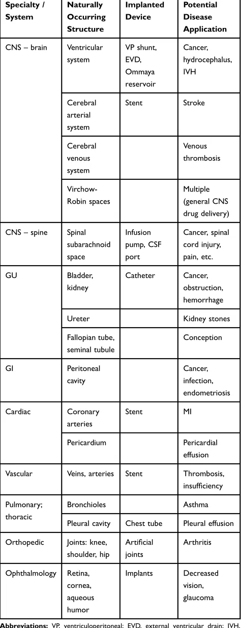
While MNP clusters might not penetrate solid tissue, they may be able to directed through conduits (such as blood vessels, lymphatics, or the spinal subarachnoid space) or across surfaces (such as the uroepithelium, or peritoneal cavity).65,83 Potential avenues and targets for MNP delivery, including
implants such as catheters, are listed inTable 3, according to
organ system and medical specialty. Adhesion of particles to the wall or surface, along with margination and wall shear, are major factors in determining whether or not MNPs will be successfully directed to their targets.84–86 Orientation of the rotating magnet will also play a critical role, and this may need to change during targeting along a complex route. Strengths arguing for the clinical use of MNP clusters include their ability
to be moved through stagnant fluid (such as to an area of
obstruction), or even against flow and pulsations.11,17,72
Uncertainties (as with MNPs in general) include their possible
long-term toxicity, and/or generation of an immune or infl
am-matory response.14Within the arterial system, formation of
emboli by MNP clusters could be a major concern and would have to be avoided, especially in organs such as the brain and
heart, until safety was ensured. Another difficulty arises from
the general incompatibility of magnets with electronic devices,
especially in complex medical environments. These issues
need to be further addressed experimentally.
Table 2(Continued).
Speed of rotation / oscillation
Nonspecific loading / adherence to MNPs
Field strength / heterogeneity
Ratio of cluster size to lane width
Permanent vs electromagnetic
External pulsations
Table 3Applications for Remote MNP-Enhanced Drug Delivery for Representative Conduits and Surfaces in the Human Body
Specialty / System Naturally Occurring Structure Implanted Device Potential Disease Application
CNS–brain Ventricular system VP shunt, EVD, Ommaya reservoir Cancer, hydrocephalus, IVH Cerebral arterial system Stent Stroke Cerebral venous system Venous thrombosis Virchow-Robin spaces Multiple (general CNS drug delivery)
CNS–spine Spinal subarachnoid space Infusion pump, CSF port Cancer, spinal cord injury, pain, etc. GU Bladder, kidney Catheter Cancer, obstruction, hemorrhage
Ureter Kidney stones
Fallopian tube, seminal tubule Conception GI Peritoneal cavity Cancer, infection, endometriosis Cardiac Coronary arteries Stent MI Pericardium Pericardial effusion
Vascular Veins, arteries Stent Thrombosis, insufficiency
Pulmonary; thoracic
Bronchioles Asthma
Pleural cavity Chest tube Pleural effusion
Orthopedic Joints: knee, shoulder, hip
Artificial joints Arthritis Ophthalmology Retina, cornea, aqueous humor Implants Decreased vision, glaucoma
Abbreviations:VP, ventriculoperitoneal; EVD, external ventricular drain; IVH, intraventricular hemorrhage; MI, myocardial infarction.
International Journal of Nanomedicine downloaded from https://www.dovepress.com/ by 118.70.13.36 on 27-Aug-2020
MNP clusters can contain more than one type of particle. Sophisticated MNP-based drug delivery vehicles have recently been reported, which combine thermotherapy and chemotherapy with encouraging results in vitro and in
lung-xenograft–bearing mice.87Hybrid MNPs have been
devel-oped, which allow for chemotherapy release in response to magnetically induced heating or a low-power radiofrequency field.88,89Delivering such particles, or particle clusters having multiple components, via conduits by the rotational mechan-ism we have described, may open up new avenues for success-ful MDT. Magnetically enhanced delivery of chemotherapy
would be expected to have greater efficacy if administered
earlier in the course of cancer dissemination. Early seedings of cancer cells could possibly be treated through access afforded by the lymphatic system, genitourinary system, and peritoneal cavity, as examples. An expected early clinical application of MIRT technology in the CNS would be in the treatment of
patients with leptomeningeal metastases.90–93 The greatest
impact would be in treating (at an early stage) cancer cells disseminating via CSF from a primary brain tumor such as medulloblastoma, since systemic metastases would not have
already occurred.94
Conclusions
Rotating MNPs clusters can be used as simple microdevices for drug delivery, including chemotherapeutic agents as we demonstrate here. Precisely directing such drug carriers
remains the“Holy Grail”of MDT.8,95Basic factors such as
magnet position and the cellular lining of the access channels must be critically analyzed by in vitro modeling in order to predict MNP behavior in vivo. Velocity and cell surface
adhesion of MNP clusters can be quantified, using video
photography and digital analysis. Further studies need to be
performed to determine whether or not MNP clusters–or
their payload–may preferentially attach to (or be taken up
by) cancer cells more than non-neoplastic cells, especially in vivo. Otherwise, additional targeting and release
mechan-isms may be required –functions for which hybrid MNPs
are well suited.73Achieving an improved understanding of
the factors that influence MNP agglomeration, stability,
translational movement, drug binding and release, and ulti-mately uptake by the target cells, will be crucial for making the jump to successful human applications of rMDT.
Acknowledgments
The authors would like to thank Hagai Ganin and Edward Jones (UIC Radiology) for their help with obtaining the CT and MRI images. We also thank Dylan Lynch (UIC
Makerspace) and Joel Rodriguez (UIC Science Instrument Shop) for assistance in milling the MIRT trays, Michelle Van Scoyk (UIC Cancer Center) for assistance with light micro-scopy, and Olivia Thompson (UIC Electron Microscopy) for assistance with SEM. The authors also thank Syed Hussain and Dr. Georgia Papavasiliou (Department of Bioengineering, Illinois Institute of Technology), for providing the Nanosight data. Data reported in this paper were presented at the Annual Meeting of the American Association for Cancer Research, Washington, D.C., April 2017; Frontiers in Biomagnetic Particles Conference, Asheville, North Carolina, June 2017; and the Annual Meeting of the American Association for Cancer Research, Chicago, Illinois, April 2018.
Funding
Funding for this project was through The Brain Tumor Research Fund at The University of Illinois at Chicago Cancer Center, Chicago, IL, USA.
Disclosure
Michael E Sabo was a full-time employee of Pulse Therapeutics Inc. from June 2009 to April 2019. Francis M Creighton was employed by Pulse Therapeutics Inc. Mr. Sabo and Dr. Creighton are currently employees of
UNandUP, Inc., St. Louis, MO, USA. A patent “Tissue
Culture Tray and System for the In Vitro Testing and Characterization of Magnetically Induced Rotation and
Translational Motion of Magnetic Particles”; July 2017
US20180024109A1 was described and used in this paper.
The authors report no other conflicts of interest in this work.
References
1. Laurent S, Saei AA, Behzadi S, Panahifar A, Mahmoudi M. Superparamagnetic iron oxide nanoparticles for delivery of therapeutic agents: opportunities and challenges.Expert Opin Drug Deliv.2014;11 (9):1449–1470. doi:10.1517/17425247.2014.924501
2. Zhu L, Zhou Z, Mao H, Yang L. Magnetic nanoparticles for precision oncology: theranostic magnetic iron oxide nanoparticles for image-guided and targeted cancer therapy.Nanomedicine (Lond). 2017;12 (1):73–87. doi:10.2217/nnm-2016-0316
3. Lee GP, Pernal SP, Shokuhfar T, Engelhard HH. Nanoparticles as therapeutic agents for patients with brain tumors. In: Newton H, editor.
Handbook of Brain Tumor Chemotherapy, Molecular Therapeutics and Immunotherapy. 2nd ed. San Diego: Academic Press;2018:229–246. 4. D’Agata F, Ruffinatti FA, Boschi S, et al. Magnetic nanoparticles in
the central nervous system: targeting principles, applications and safety issues.Molecules.2017;23:1. doi:10.3390/molecules23010009 5. Amreddy N, Babu A, Muralidharan R, et al. Recent advances in
nanoparticle-based cancer drug and gene delivery.Adv Cancer Res. 2018;137:115–170. doi:10.1016/bs.acr.2017.11.003
6. Chenthamara D, Subramaniam S, Ramakrishnan SG, et al. Therapeutic efficacy of nanoparticles and routes of administration.Biomater Res. 2019;23:20. doi:10.1186/s40824-019-0166-x
International Journal of Nanomedicine downloaded from https://www.dovepress.com/ by 118.70.13.36 on 27-Aug-2020
7. Cao Q, Han X, Li L. Enhancement of the efficiency of magnetic targeting for drug delivery: development and evaluation of magnet system.J Magn Magn Mater.2011;323(15):1919–1924. doi:10.1016/ j.jmmm.2010.11.058
8. Shapiro B, Kulkarni S, Nacev A, Muro S, Stepanov PY, Weinberg IN. Open challenges in magnetic drug targeting.Wiley Interdiscip Rev Nanomed Nanobiotechnol.2015;7(3):446–457. doi:10.1002/wnan.1311 9. Chang M, Lin Y-H, Gabayno JL, Li Q, Liu X. Thrombolysis based on magnetically-controlled surface-functionalized Fe3O4 nanoparticle. Bioengineered. 2017;8(1):29–35. doi:10.1080/21655979.2016.12 27145
10. Engelhard HH, Pernal SP, Gaertner ZA, et al. A novel tissue culture tray for the study of magnetically induced rotation and translation of iron oxide nanoparticles.IEEE Magn Lett.2017;8:1–5. doi:10.1109/ LMAG.2017.2761818
11. Pernal S, Willis A, Sabo M, et al. An in vitro model system for evaluating remote magnetic nanoparticle movement andfi brinoly-sis. Int J Nanomedicine. 2020;15:1549–1568. doi:10.2147/IJN. S237395
12. Zhi D, Yang T, Yang J, Fu S, Zhang S. Targeting strategies for superparamagnetic iron oxide nanoparticles in cancer therapy.Acta Biomater.2020;102:13–34. doi:10.1016/j.actbio.2019.11.027 13. Singh D, McMillan JM, Kabanov AV, Sokolsky-Papkov M,
Gendelman HE. Bench-to-bedside translation of magnetic nanoparti-cles.Nanomedicine (Lond).2014;9(4):501–516. doi:10.2217/NMM. 14.5
14. Bayda S, Hadla M, Palazzolo S, et al. Inorganic nanoparticles for cancer therapy: a transition from lab to clinic.Curr Med Chem. 2018;25(34):4269–4303. doi:10.2174/0929867325666171229141156 15. Maia FR, Reis RL, Oliveira JM. Finding the perfect match between nanoparticles and microfluidics to respond to cancer challenges.
Nanomedicine.2019;24:102139. doi:10.1016/j.nano.2019.102139 16. Ghosh A, Fischer P. Controlled propulsion of artificial magnetic
nanostructured propellers.Nano Lett.2009;9(6):2243–2245. doi:10. 1021/nl900186w
17. Karle M, Wöhrle J, Miwa J, et al. Controlled counter-flow motion of magnetic bead chains rolling along microchannels. Microfluid
Nanofluidics.2011;10(4):935–939. doi:10.1007/s10404-010-0727-8 18. Singh H, Laibinis PE, Hatton TA. Rigid, superparamagnetic chains of
permanently linked beads coated with magnetic nanoparticles: synth-esis and rotational dynamics under applied magnetic fields.
Langmuir.2005;21(24):11500–11509. doi:10.1021/la0517843 19. Kang TG, Hulsen MA, Anderson PD, den Toonder JMJ, Meijer
HEH. Chaotic mixing induced by a magnetic chain in a rotating magnetic field. Phys Rev E. 2007;76(6):066303. doi:10.1103/ PhysRevE.76.066303
20. Petousis I, Homburg E, Derks R, Dietzel A. Transient behaviour of magnetic micro-bead chains rotating in afluid by externalfields.Lab Chip.2007;7(12):1746. doi:10.1039/b713735b
21. Roy T, Sinha A, Chakraborty S, Ganguly R, Puri IK. Magnetic microsphere-based mixers for microdroplets.Phys Fluids.2009;21 (2):027101. doi:10.1063/1.3072602
22. Wilson RJ, Hu W, Fu CW, et al. Formation and properties of mag-netic chains for 100 nm nanoparticles used in separations of mole-cules and cells. J Magn Magn Mater. 2009;321(10):1452–1458. doi:10.1016/j.jmmm.2009.02.066
23. Mørup S, Hansen MF, Frandsen C. Magnetic interactions between nanoparticles. Beilstein J Nanotechnol. 2010;1:182–190. doi:10. 3762/bjnano.1.22
24. Ganguly R, Puri IK. Microfluidic transport in magnetic MEMS and bioMEMS.Wiley Interdiscip Rev Nanomed Nanobiotechnol.2010;2 (4):382–399. doi:10.1002/wnan.92
25. Etheridge ML, Hurley KR, Zhang J, et al. Accounting for biological aggregation in heating and imaging of magnetic nanoparticles.
Technology (Singap World Sci). 2014;2(3):214–228. doi:10.1142/ S2339547814500198
26. Wang C, Hsu CH, Li Z, et al. Effective heating of magnetic nano-particle aggregates for in vivo nano-theranostic hyperthermia.Int J Nanomedicine.2017;12:6273–6287. doi:10.2147/IJN.S141072 27. Gädke J, Thies J-W, Kleinfeldt L, et al. Selective manipulation of
superparamagnetic nanoparticles for product purification and micro-fluidic diagnostics. Eur J Pharm Biopharm. 2018;126:67–74. doi:10.1016/j.ejpb.2017.09.008
28. Guibert C, Dupuis V, Peyre V, Fresnais J. Hyperthermia of magnetic nanoparticles: experimental study of the role of aggregation.J Phys Chem C.2015;119(50):28148–28154. doi:10.1021/acs.jpcc.5b07796 29. Ramaswamy B, Kulkarni SD, Villar PS, et al. Movement of magnetic
nanoparticles in brain tissue: mechanisms and impact on normal neuronal function.Nanomedicine.2015;11(7):1821–1829. doi:10.10 16/j.nano.2015.06.003
30. Mair LO, Weinberg IN, Nacev A, et al. Analysis of driven nanorod transport through a biopolymer matrix. J Magn Magn Mater. 2015;380:295–298. doi:10.1016/j.jmmm.2014.09.059
31. Soheilian R, Choi YS, David AE, Abdi H, Maloney CE, Erb RM. Toward accumulation of magnetic nanoparticles into tissues of small porosity.
Langmuir.2015;31(30):8267–8274. doi:10.1021/acs.langmuir.5b01458 32. Engelhard H, Gaertner Z, Levin A, et al. Rotating magnetic beads for
enhanced drug delivery: characterization of bead velocity, imaging, and adherence to cellular monolayers, abstract 3104. Am Assoc Cancer Res.2017;3104. doi:10.1158/1538-7445.AM2017-3104 33. Pouponneau P, Leroux J-C, Martel S. Magnetic nanoparticles
encapsu-lated into biodegradable microparticles steered with an upgraded magnetic resonance imaging system for tumor chemoembolization.Biomaterials. 2009;30(31):6327–6332. doi:10.1016/j.biomaterials.2009.08.005 34. Pernal SP, Willis AJ, Engelhard HH. Magnetic nanoparticles (MNPs) for
cancer drug delivery: the value of in vitro modeling, abstract 4661.Am Assoc Cancer Res.2018;4661. doi:10.1158/1538-7445.AM2018-4661 35. Cao Q, Han X, Li L. Configurations and control of magneticfields
for manipulating magnetic particles in microfluidic applications: magnet systems and manipulation mechanisms.Lab Chip.2014;14 (15):2762–2777. doi:10.1039/c4lc00367e
36. Pajtler KW, Tippelt S, Siegler N, et al. Intraventricular etoposide safety and toxicity profile in children and young adults with refrac-tory or recurrent malignant brain tumors. J Neurooncol.2016;128 (3):463–471. doi:10.1007/s11060-016-2133-x
37. Venugopal I, Pernal S, Duproz A, Bentley J, Engelhard H, Linninger A. Magneticfield-enhanced cellular uptake of doxorubicin loaded magnetic nanoparticles for tumor treatment. Mater Res Express. 2016;3(9):095010. doi:10.1088/2053-1591/3/9/095010
38. Sarwar A, Nemirovski A, Shapiro B. Optimal halbach permanent magnet designs for maximally pulling and pushing nanoparticles.J Magn Magn Mater.2012;324(5):742–754. doi:10.1016/j.jmmm.2011.09.008 39. Zhu Q, Jiang L, Wang X. The expression of duffy antigen receptor
for chemokines by epithelial ovarian cancer decreases growth poten-tial.Oncol Lett.2017;13(6):4302–4306. doi:10.3892/ol.2017.5954 40. Fountain TWR, Kailat PV, Abbott JJ Wireless control of magnetic helical
microrobots using a rotating-permanent-magnet manipulator. In: 2010 IEEE International Conference on Robotics and Automation; 2010; Anchorage, AK: IEEE: 576–581. doi:10.1109/ROBOT.2010.5509245 41. Cheng R, Huang W, Huang L, et al. Acceleration of tissue
plasmino-gen activator-mediated thrombolysis by magnetically powered nano-motors.ACS Nano.2014;8(8):7746–7754. doi:10.1021/nn5029955 42. Lundqvist M, Stigler J, Elia G, Lynch I, Cedervall T, Dawson KA.
Nanoparticle size and surface properties determine the protein corona with possible implications for biological impacts.Proc Natl Acad Sci USA.2008;105(38):14265–14270. doi:10.1073/pnas.0805135105 43. Walczyk D, Bombelli FB, Monopoli MP, Lynch I, Dawson KA. What
the cell “sees” in bionanoscience. J Am Chem Soc. 2010;132 (16):5761–5768. doi:10.1021/ja910675v
44. Walkey CD, Chan WCW. Understanding and controlling the interac-tion of nanomaterials with proteins in a physiological environment.
Chem Soc Rev.2012;41(7):2780–2799. doi:10.1039/c1cs15233e
International Journal of Nanomedicine downloaded from https://www.dovepress.com/ by 118.70.13.36 on 27-Aug-2020