IMPLEMENTATION OF HIGH SPEED DATA
TRANSMISSION USING VLC
Sarah Monica
. S
1, V. Muralidharan
21
UG Scholar/ECE.,
2Assistant Professor/ECE Christ the King Engineering College, (India)
ABSTRACT
In recent trends, wireless communication Wi-Fi is gaining tremendous importance. Today connectivity is of
greater concern. In-flight Wi-Fi is now accessible around 40%, but there subsist problems since connection is
slow and unreliable. Wi-Fi is also menacing and by means of satellite which is economically unsurpassable.
Hence to overcome this with a reliable one there comes LI-FI Technology. In this LED is used for data
transmission by switching it ON(1) and OFF(0) posthastly in nanoseconds which is not seen by naked eyes.
Li-Fi provides internet connectivity up to 10Gbps.We can employ this technology of wireless communication in
more electromagnetic sensitive area that is in aircraft for traffic management.
Keywords: LED, VLC, Wi-Fi
I. INTRODUCTION
Light fidelity is an exciting quantum leap in 5G VLC system and the future of wireless internet access. Wi-Fi
plays a role in aircraft communication but it's not durable and its getting lessen importance due to these
following reasons given below [2]
Physical Obstructions
Network range and distance between devices
Wireless network interference
Signal sharing
Network usage and load
Wireless signal restriction
The above hitch ill in Wi-Fi technology can be overcome by Li-Fi technology. It's very simple, if the LED is
ON, you transmit digital 1 if it‟s OFF you transmit a 0. The LEDs can be switched on and off very quickly, which gives nice opportunities for transmitting data[5], [6].„Internet of Things‟ is an optical communication technology that‟s taking the world by storm. Light Fidelity or Li-Fi, is an exciting breakthrough in 5G visual
light communication systems and the future of wireless Internet access. With Li-Fi, information hitches a ride
along a spectrum of visible light. Light emitting diode (LED) bulbs transmit data when they are switched on and
phones will soon be able to download traffic information from traffic lights or a program guide from a
television.
II. LITERATURE SURVEY
In 2011, Professor Harold Haas from the University of Edinburgh in the UK, suggested an idea called “Data through illumination” [4]. He used fibre optics to send data through LED light bulbs. Light modulation certainly
is not a new concept, but Haas is looking to move things forward and enable connectivity through simple LED
bulbs. With Li-Fi, we can connect to the internet simply by being within range of an LED beam, or we could
conceivably transmit data using our car headlights. The ramifications of this are huge, especially with the
internet of things in full swing and the much mooted spectrum crunch expected to bite increasingly hard in the
coming years.
LI-FI is a new technology which uses visible light for communication instead of radio waves. It refers to 5G
Visible Light Communication systems using Light Emitting Diodes as a medium to high-speed communication
in a similar manner as WI-FI [6]. It can help to conserve a large amount of electricity by transmitting data
through light bulbs and other such lighting equipments. It can be used in aircrafts without causing any kind of
interference. LI-FI uses light as a carrier as opposed to traditional use of radio waves as in WI-FI and this means
that it cannot penetrate walls, which the radio waves are able to. It is typically implemented using white LED
bulbs at the downlink transmitter [1]. By varying the current through the LED at a very high speed, we can vary
the output at very high speeds. This is the principle of the LI-FI. The working of the LI-FI is itself very simple—
if the LED is ON, the signal transmitted is a digital 1 whereas if it is OFF, the signal transmitted is a digital 0.
By varying the rate at which the LEDs flicker, we can encode various data and transmit it.
Li-Fi is no longer a concept or an idea but a proven technology, albeit still at its infancy. Already, several
experts in the field of communication have attested that Li-Fi technology would soon become a standard adjunct
to Wi-Fi. That is, until its inherent limitations could be overcome. Since it is light-based, its major drawback is
that it won‟t be able to penetrate solid objects such as walls. Though it could also mean privacy for the personal
III. EXISTING METHOD
Wireless Fidelity (Wi-Fi) uses radio waves to send and receive information. in fact, its lot like two way radio
communication. A PC or Wi-Fi devices translates the data into radio signals and transmits using antenna. A
wireless access point receives the signal, decodes it, then sends info to internet
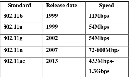
Table 1: Various Standards Used and Their Data Rate Speed
Standard Release date Speed
802.11b 1999 11Mbps
802.11a 1999 54Mbps
802.11g 2002 54Mbps
802.11n 2007 72-600Mbps
802.11ac 2013
433Mbps-1.3Gbps
Earlier 802.11a/b/g networks relied on single antenna and single data stream. With the introduction of 802.11n
specification, Wi-Fi can harness the power of up to three antennas and streams to dramatically improve
speed, range and reliability.802.11ac builds on these improvement with capability to transmit to and receive
from multiple users at the same time(instead of one at a time) by using multiuser MIMO(MU-MIMO)
technology.80.11ac supports up to three antennas and streams today and will be able to support up to eight
antennas in the future. Throughput which is more accurate measurement of Wi-Fi network speed takes into
account all the bits eaten up by network overhead and environmental factors. Although the touted data- rate
speeds don't happen in the real world, they still serve as a useful benchmark. In general, the higher the data-rate
speeds, the higher the corresponding throughput. In addition, the data rate drops with each new connected
device.
In Wi-Fi throughput is not ideal is various accordingly to the thrive in a crowded Wi-Fi world [5]. All this
congestion is already straining the capabilities of the existing Wi-Fi standard 802.11n, and slowing down your
digital life. As the 802.11 specification[8] evolved to support higher throughput, the bandwidth requirements
also increased to support them.802.11n uses double the radio spectrum/ bandwidth(40Mhz) compared to
802.111a or 802.11g(20Mhz)[citation needed].This means there can be only 802.11n network on the 2.4Ghz
band at a given location, without interference to/from other WLAN traffic. 802.11n can also be set to limit itself
to 20 MHz bandwidth to prevent interference in dense community. Now many newer consumer devices support
the latest 802.11ac standard, which uses the 5Ghz band exclusively and is capable of multi-station WLAN
throughput of at least 1Gigabit per second. Wi-Fi connections can be disrupted or the internet speed lowered
by having other devices in the same area. Many 2.4Ghz 802.11b and 802.11g access-points default to the same
channel on initial startup, contributing to congestion on certain channels. Wi-Fi pollution, or an excessive
Table 2: Comparison of Speed of Various Wireless Technologies Technology Speed Wi-Fi –
Ieee
802.11n 150Mbps
Bluetooth 3Mbps
IrDA 4Mbps
Li-Fi >1Gbps
IV. PROPOSED METHOD
LI-FI means transmission of data through illumination (i.e. sending data through a LED light bulb) that varies in
intensity faster than human eye can follow and its not visible to our naked eyes
.
5.1 Audio and Video Transmission
S/PDIF Converter (Sony/ Phillips Digital Interface) is most commonly used standard format for digital data
transmission. S/PDIF is a data link layer protocol, which contains a set of physical layer specifications for
carrying digital audio signals between devices and components over either optical or electrical cables. Its
employing small differences in the protocol and requiring less expensive hardware. In S/PDIF, the digital data
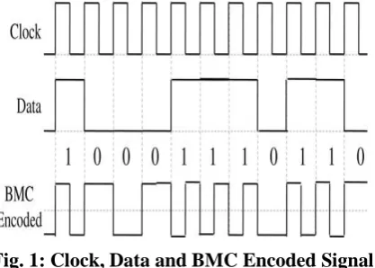
stream is encoded using the bi-phase mark code (BMC) also known as the differential Manchester encoding,
which is a kind of phase modulation in which clock and data signals are combined to form a single two-level
self-synchronizing bit stream (see Figure 1), where the level change occurs at the beginning of every bit period.
Its a differential encoding scheme, it uses the presence or absence of transitions to indicate a logic values.
Logics 1 and 0 are represented by mid-bit and no mid-bit level changes thereby offering built-in
synchronization capabilities[6]
Fig. 1: Clock, Data and BMC Encoded Signal
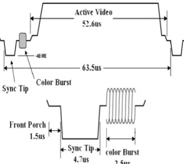
Analog TVs adopt a composite video signal commonly used analog video interface. Composite video is also
referred to s CVBS(Colour Video Blanking and Sync) or the composite video baseband signal, which combines
the brightness information (luma), the colour information (chroma), and the synchronizing signal just on one
Fig. 2: The All-White NTSC Composite Video Signal.
There are three standard analog TV formats such as Phase Alternating Line(PAL), National Television System
Committee (NTSC), and Sequential Colour with Memory (SECAM). PAL uses 4.43 MHZ, NTSC uses 3.58
Mhz, and SECAM uses 4.53 MHZ colour subcarriers. A very high bit rate is required if we use analog-to-digital
conversion (ADC) for video transmission. For example, with an 8-bit ADC, the sampling rate must be 10MS/s
and the resulting output data rate from the ADC, the sampling rate must be 10MS?s and the resulting output
data rate from the ADC for video transmission will be 80Mb/s. The maximum modulation frequency of the
ordinary high-brightness LED is around 20Mhz, which is not sufficient to support 80 Mb/s. Therefore, one
solution would be to employ pulse time modulation schemes such as Pulse Width Modulation (PWM), Pulse
Frequency Modulation (PFM),Square wave FM,etc..,
5.2 Audio and Video Transmitter
The schematic diagrams of audio and video transmitter modules are illustrated in Figure3. In Figure3a, the
analog audio signal is amplified and digitized prior to being converted into an S/PDIF format. The S/PDIF audio
signal drives a 4 × 5 white LED cluster made up of blue LEDs with yellow phosphor. In Figure 3b, the
amplified analog video signal that passed through a band-pass filter is compared with the reference saw tooth
carrier signal, which generates the naturally sampled PWM signal that drives a 5*5 red LED cluster. The colours
The output of the ADC is an Inter-IC Sound (I2S) signal, which includes a master clock, bit clock, left right
clock, and data clock. The I2S signal is then converted to the S/PDIF signal. The S/PDIF signal data stream
consists of a series of 1 and 0 digital bits that describe the audio waveforms. The colour subcarrier frequencies,
fc-sub, of the analog video signal are 4.43361875 and 3.579545 MHz for PAL and NTSC, respectively. The
composite video signal following amplification and filter is compared with the linear ramp carrier signal at a
frequency of 15Mhz, which is only four or five times fc-sub, using a high-speed comparator (with the propagation
delay and rise/fall times of 4.5 and 1.5ns respectively).
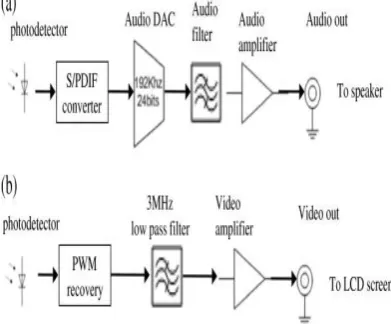
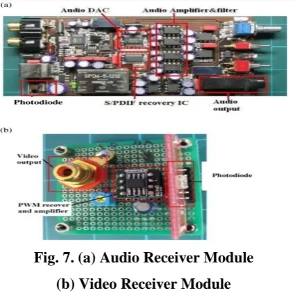
5.3 Audio and Video Reception
Two different types of PDs were used for the audio and video signals. For the audio part, the output of a
low-speed PD (i.e., 15 Mb/s with a receiver sensitivity of -24 dBm) is first passed through the S/PDIF module
followed by a high-quality stereo audio digital-to-analog converter (DAC) module. We have chosen a 192-kHz,
24-bit advanced segment stereo DAC for a high-quality audio signal. Filtering and amplification ensures the
required audio output level. For the video link, a high-speed PD (i.e., 50 Mb/s with a receiver sensitivity of -17.5
dBm) followed by the PWM demodulator, a 3-MHz filter, and a video amplifier are used to recover the video
signal. Figure 8 shows the audio and video receiver modules [6].
Fig. 4: Receiver system block diagram
(a)Audio (b) Video
V. IMPLEMENTATION AND RESULT
Fig. 6: Video Transmitter Module
There are a number of ICs available for the audio ADC. Here we have chosen a very simple chip (AK5386 from
Asahi-Kasei, Chiyoda, Tokyo, Japan), which is a stereo A/D converter with a wide-ranging sampling rate from
8 to 216 kHz, widely used in both consumer and professional audio systems. The technology is based on
enhanced dual-bit ΔΣ scheme, thus offering a high accuracy and a low cost.
Fig. 7. (a) Audio Receiver Module
(b) Video Receiver Module
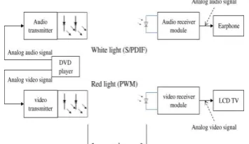
The transmission of audio and video signals using the developed modules has been demonstrated
experimentally. The experimental setup is shown in Figure 8. A DVD player is used to generate both the audio
and video signals. The white and red light sources are used for transmission of audio and video signals,
respectively. At the receiver, LCD TV and speakers are used to monitor the quality of the video and audio
signals following post photo detection processing. As shown in Figure 9, transmitters and receivers were placed
in a directed diffuse link configuration, with 10-cm spacing between the two transmitter modules. The
transmission span was set at 50 cm with no lenses. The link distance can be extended by using appropriate
Fig. 8: The Overall Experimental Setup
Comparsion Between Li-Fi & Wi-Fi
VI. CONCLUSION
Li-Fi is an emerging technology in world of internet .This just uses incoherent light source i.e. LED is used here.
The transfer of the data can be with the help of all kinds of light, no matter the part of the spectrum that they
belong. That is, the light can belong to the invisible, ultraviolet or the visible part of the spectrum. Also, the
speed of the communication is more than sufficient for downloading movies, games, music and all in very less
time. Though Wi-Fi gives us speed up to 150mbps as per IEEE 802.11n, it is still insufficient to accommodate
number of desired users. Li-Fi has 1000 times wider bandwidth than Wi-Fi. Also it provides more security as it
cannot penetrate through walls. By using an array of LED speed up to 10Gbps can be obtained. Thus Li-Fi can
be used as an alternate to high speed wireless network for communication.
REFERENCE
[1] m.techradar.com/news/world-of-tech/future-tech
/How-does-airplane-Wi-Fi-work-And-will-it-ever-get-any-better/articleshow/38758474.cms
[2]. www.4gon.co.nk/solution/technical_factors_affecting_wireless_performance.php
[3]. Li-Fi Technology Transmission of data through light ISSN:2229-6093
[4] visiblelightcomm.com/5-reasons-to-promote-lifi-technologies/
[5]. David Angell Next-Gen 802.11ac Wi-Fi for dummies
[6]. Simultaneous transmission of audio and video signals using visible light communication
[7].https://en.m.wikipedia.org/wiki/Wi-Fi
[8]. Light-Fidelity: A Reconnaissance of Future Technology International Journal of Advanced Research in