264 |
P a g e
HUMAN POWERED FLYWHEEL MOTOR BY USING
QUICK RETURN RATIO ONE MECHANISM
K. K. Padghan¹, Prof. A.K. Pitale², Prof J. P.Modak³ ,A.P. Narkhedkar
41
Scholor M.E. (CAD/CAM),PRMIT &R, Badnera,( India)
2
Professor,Dept of Mech. Engg. PRMIT.&.R,Badnera,(India
)
3
Emeritus Professor, Dept of Mech Engg ,Priyadarshani C.O.E.Nagpur,(India)
4
Scholor M.E. (CAD/CAM),PRMIT&R,Badnera,(India)
ABSTRACT
In these days of energy crisis bicycle has remained the only resort as a means of personnel transport in under
developed and developing countries. Every effort should be made in improving the performance of the bicycle.
There is another reason to improving the performance of the bicycle drive is that, the bicycle drive mechanism
is used as a means for converting human energy in the form of mechanical energy in the case of cycle rickshaw
and in the case of some manually driven process machines.
Flywheel is used in manually driven machines, mainly as flywheel motor. Flywheel is pedaled to a higher speed
to store kinetic energy. This K.E. is drained out in a short period to accomplish a desired process which needs
process power beyond human capacities. The pedal operated flywheel provides a wide aspect of living in a
different way. It gives us a way to produce energy by the use of human effort.
The following report proposes the use of a pedal operated flywheel to maximize K.E. gain and its optimization.
The report firstly defines the problems associated with maximizing the K.E. gain and its use. Subsequent section
will compare different types of bicycle mechanism and describe it briefly. The remainder of the report will focus
on the optimization of human powered flywheel motor to maximize K.E. gain. To have increased efficiencies,
flywheel motors have some special arrangements of inputting power. They are, 1) Quick return ratio one, 2)
Elliptical chain wheel, and 3) Double lever inversion. Hence in this paper arrangement and testing values of
Quick return ratio one is presented on flywheel motor.
KEY WORDS
: - Quick return Ratio-one, Flywheel motor, kinetic energy gain.I. INTRODUCTION
During 1979-99, Modak J.P. developed a human powered brick making machine for the manufacturing of bricks
(Modak J.P. J.P. 1982, 1994, 1997, 1998) [1]. And since then various processes are energized by the human
power such as wood turning, cloth washing, chaff cutter [2], potter’s wheel, flour mill etc. All these machines
are operated by the human power with one common mechanism among them- The Flywheel Motor. The
265 |
P a g e
the shaft of process of process unit through clutch and torque amplification unit (Gupta 1977)[1]. Since ever
increasing fuel crises, energy crises, busy schedules of load shading, unemployment justify the need of human
powered machines, the constants efforts are being continuously made to optimize the various parameters of
these machines so as to provide the ease for the operator and consequently make efficient use of human energy.
In an attempt, this paper presents the exhaustive literature survey on the flywheel motor throwing lights on the
experimentation done on flywheel motor with double lever inversion for optimizing its performance.
II. FLYWHEEL MOTOR THE CONCEPT
Any machine, to power it by human energy, the maximum power requirement should be 75Watts. Any machine
or process requiring more than 75 Watts and if process is intermittent without affecting and product, can also be
operated by human energy ( Alexandrove 1981)[3]. This is possible with the provision of intermediate energy
storing unit which stores the energy of human and supply periodically at required rate to process unit, this is
called as “human powered flywheel motor.”Modak J.P. and his associates are working on flywheel motor from
1977. A manually driven brick making machine was first of its kind in which manually energized flywheel
motor is used for first time [4]. Essentially the flywheel motor consists of flywheel, which is being driven by a
human through a simple bicycle mechanism and pair of speed increasing gears [3]. The schematic of flywheel
motor is as shown in fig1.
Fig: Schematics of flywheel motor.
A rider pedals the mechanism „M‟ converting the oscillatory motion of thighs into rotational motion of counter shaft „C‟. This countershaft „C‟ connected to flywheel shaft „FS‟ with speed increasing transmission consisting
of pair of speed gears [4].Driver pumps the energy in flywheel at energy rate convenient to him [4]. In this way,
the muscular energy of human is converted into kinetic energy of flywheel by this man machine and for its
266 |
P a g e
III. DESIGN CONSIDERATION IN FLYWHEEL MOTOR.
At the beginning, the flywheel motor was not based on any design data, rather it was built only on the institution
of human[4]. Later with the numerous experimentation the design data is made available which is discussed
below.
A.
MODIFICATION IN EXISTING BICYCLE MECHANISM.
Modak J.P (1985) has established the relationship between the useful torques developed at the crank as function
of crank position during its revolution [5]. Modak J.P. also observed that out of 360° rotation of pedal crank,
only from 30°-115° of crank position from top dead center is useful. The rest of the period of crank position i.e.
0°-30° and 115°-162° is not effectively used and from 162°-360° is completely idle. Even when both the cranks
are considered the useful driving angle is found to be 154°.[5]. Consequently for maximum utilization of
operators energy Modak J.P. suggested three modified mechanisms namely Quick return ratio one, Double lever
inversion and Elliptical sprocket[5].Based on his mathematical modeling he concluded improvement of
17%,38%, and 18% in human energy utilization for Quick return ratio one, Double lever inversion and Elliptical
sprocket respectively. This performance of various bicycle drives then was experimentally verified by Modak
J.P , Chandurkar K.C. et ,al (1987) and found almost matching with theoretical values[6].
B.
FLYWHEEL SPEED AND MOMENT OF INERTIA
Modak J.P(1987) during the experimentation has ob-served the maximum thigh oscillation for the average
person of 165 cm stature from age group 20-22 years is 40. [7]. With the available chain drive for existing 22”
bicycle frame the flywheel speed of 240 rpm was fair enough from point of total speed rise from pedals to
flywheel shaft [7]. Further with calculation Modak J.P.(1987) has deter-mined the size of flywheel with the
objective to store the maximum energy irrespective of speed fluctuations(180-240 rpm)[7]. The Flywheel rim
diameter is found to 82 cm which gives the weight of flywheel as 150Kg and 266 Kg for 240 rpm and 180 rpm
respectively. Hence Modak J.P.(1987) suggested the flywheel with 150 Kg @240 rpm[7]. Further Modak
J.P.(1987) has also found that driving tor-que of pedal is unaffected by increasing flywheel moment of inertia
and stores same energy for same frequency of thigh oscillation [7].
C.
GEAR RATIO
Modak J.P. (1987) suggested the value of gear ratio as 4:1 so as to reduce the effect of jerk induced at process
unit shaft as result of energy or momentum exchange during the clutch engagement. If lower value of gear ratio
is to be used then flywheel speed should be maintained higher than 240 rpm [7].
Quick return ratio-one:-
From figure O1B is thigh length, AB is length,
267 |
P a g e
Fig: Modified Mechanism (Quick Return Ratio = 1)
It is modified form of mechanism called as Quick Return Ratio One. In the existing mechanism, the
ratio of forward travel to return travel is 0.82. In the Quick Return Ratio One, the ratio is one therefore, the
second paddle will be immediately ready when the first one goes down.
In this, the thigh oscillation angle, thigh length and the leg length are kept same. In existing
mechanism, the crank length is 18.5 cm and in QRR- one it is 20 cm.
Similarly, in existing mechanism the frame length i.e. crank centre to rider’s hip joint 74 cm and frame
inclination to vertical is 200. But in QRR-one, the frame length i.e. Crank centre to rider’s hip joint 67cm and
frame inclination to vertical is 110
CAD MODELING OF FABRICATED HUMAN POWERED FLYWHEEL MOTOR WITH QUICK
RETURN RATIO ONE BY USING PRO-E
268 |
P a g e
IV. THE READINGS AND CALCULATION FOR KINETIC ENERGY DEVELOPED IN
TESTS OF ACTUAL SETUP.
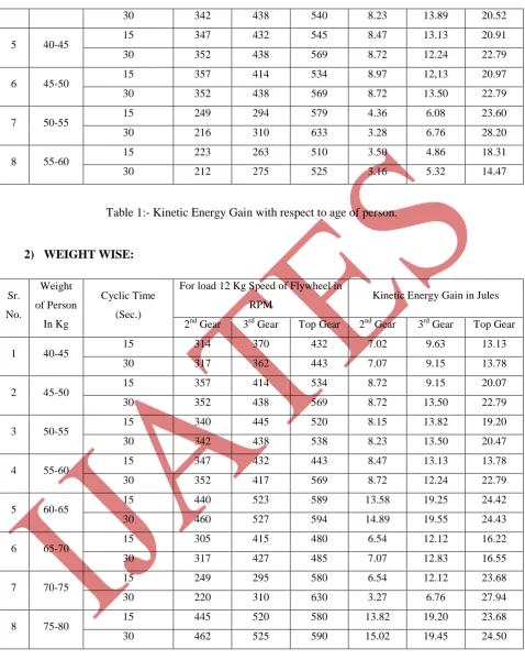
When the model of human powered flywheel motor with quick return ratio one was fabricated in our lab, we
took readings of kinetic energy for 15 and 30 seconds, with 2nd , 3rd, and top gear. First we did this for weight
wise for eight weight groups between 40-80 kg. Then we did this for age wise for eight age groups between
20-60.
Calculations for Kinetic energy stored in flywheel.
Assuming the density for the flywheel material as7874 kg/m3 i.e., for cast iron and weight
of arm and hub to be 15% more to be multiplied to moment of inertia of flywheel of rim.
The dimensions of the flywheel are as follows:
Outside diameter of flywheel (Do) = 40cm = 400mm
Rim thickness (h) = 0.05 Cm = 5mm
Width of the flywheel (b) = 0.6 Cm. = 60mm
The following figure shows the dimensional details of the flywheel.
Fig: Dimension of the flywheel
Now the mass of the flywheel is given by,
Mass= volume x density.
Volume of the flywheel is calculated as follows
Mass = [(ПD*Area] *[Density] Mass = [(ПD*(b*t)] *[Density] Mass = [(П*0.4*(0.06*0.005)] *[7874]
Mass =2.968 Kg. s
=3Kg (Approx.)
269 |
P a g e
I = w/g*(k2)
I = 3/9.81* (0.22)
I = 0.0122 kg.s.m2
Consider Weight of Arm and hub.
M. I. Flywheel = 0.0122*1.15
= 0.01403
= 0.015 kg.s.m2 (Approximately)
Kinetic Energy Stored in Flywheel
= ½ Iw2
= ½*0.0122*(2ПN/60)2
K.E. = ½ *0.0122*(2П/60)2*N2
K.E. = 6.6894*10-5*N2 Joules.
Consider RPM = 445 Second Gear,
Kinetic Energy (K.E) = 6.6894*10-5*4452 Joules.
=13.24 Joules.
Consider RPM = 523 Third Gear,
Kinetic Energy (K.E) = 6.6894*10-5*5232 Joules.
=18.85 Joules.
Consider RPM = 558 Top Gear,
Kinetic Energy (K.E) = 6.6894*10-5*5582 Joules.
=21.46 Joules.
Similarly the kinetic energy stored for each case is calculated .
1)
AGE WISE:
Sr.
No.
Age of
Person
In Year
Cyclic Time
(Sec.)
For load 12 Kg Speed of Flywheel in
RPM Kinetic Energy Gain in Jules
2nd Gear 3rd Gear Top Gear 2nd Gear 3rd Gear Top Gear
1 20-25 15 445 523 558 13.24 18.85 21.46
30 469 530 590 15.48 19.77 24.50
2 25-30 15 305 415 480 6.54 12.12 16.22
30 317 427 485 7.07 12.83 16.55
3 30-35 15 315 423 510 6.98 12.59 18.31
30 320 438 523 7.20 13.50 19.25
270 |
P a g e
30 342 438 540 8.23 13.89 20.52
5 40-45 15 347 432 545 8.47 13.13 20.91
30 352 438 569 8.72 12.24 22.79
6 45-50 15 357 414 534 8.97 12,13 20.97
30 352 438 569 8.72 13.50 22.79
7 50-55
15 249 294 579 4.36 6.08 23.60
30 216 310 633 3.28 6.76 28.20
8 55-60 15 223 263 510 3.50 4.86 18.31
30 212 275 525 3.16 5.32 14.47
Table 1:- Kinetic Energy Gain with respect to age of person.
2)
WEIGHT WISE:
Sr.
No.
Weight
of Person
In Kg
Cyclic Time
(Sec.)
For load 12 Kg Speed of Flywheel in
RPM Kinetic Energy Gain in Jules
2nd Gear 3rd Gear Top Gear 2nd Gear 3rd Gear Top Gear
1 40-45 15 314 370 432 7.02 9.63 13.13
30 317 362 443 7.07 9.15 13.78
2 45-50 15 357 414 534 8.72 9.15 20.07
30 352 438 569 8.72 13.50 22.79
3 50-55 15 340 445 520 8.15 13.82 19.20
30 342 438 538 8.23 13.50 20.47
4 55-60
15 347 432 443 8.47 13.13 13.78
30 352 417 569 8.72 12.24 22.79
5 60-65 15 440 523 589 13.58 19.25 24.42
30 460 527 594 14.89 19.55 24.43
6 65-70 15 305 415 480 6.54 12.12 16.22
30 317 427 485 7.07 12.83 16.55
7 70-75 15 249 295 580 6.54 12.12 23.68
30 220 310 630 3.27 6.76 27.94
8 75-80
15 445 520 580 13.82 19.20 23.68
30 462 525 590 15.02 19.45 24.50
271 |
P a g e
V. CONCLUSION
Due to ever increasing energy crises the use of human energized machines are increasing day by day. The
numbers of advantages are associated with this such as unavailability of power specially in rural side of India,
less skilled operators, unemployment, bicycle exercising etc. Hence human power machines seem to have great
future ahead. In this paper the HPFM with Quick return ratio mechanism is proposed. As well as the readings of
kinetic energy developed for limited period, weight wise and age wise, are tabulated.
REFERENCES
[1] Modak J.P “Bicycle and its kinematics and modifica-tions”. National conference mach Mech; February 1985;pp5-11
[2] Modak J.P, Bapat A.R. “ Improvement in experimen-tal setup for establishing generalized experimental model of various dynamic responses for A manually energised flywheel motor”
[3] Modak J.P, Bapat A.R. “Various efficiencies of hu-man powered flywheel motor” Human power number volume 54;pp21-23
[4] Modak J.P “ design and development of human ener-gised chaff cutter”
[5] Modak J.P , Moghe S.D “Design and development of human powered machine for the manufacture of lime flyash sand bricks” Human power; volume 13 num-ber2;1998;pp3-7.
[6] Modak J.P. , Chandurkar K.C., Singh M.P, Yadpana-war A.G “Experimental verification of various bi-cycle drive mechanism part1” Proceedings of AMSE conference modeling and simulation Karisurhe west Germeny, july 20-22 1987;pp139-160.
BIOGRAPHIES
K.K. PADGHAN is M.E. Scholar at Prof. Ram Meghe Institute of
technology and research Badnera, Maharashtra, India. He is basically
Mechanical Engineer from Prof. Ram Meghe Institute of technology and
research Badnera, Maharashtra, India.. Presently he is pursuing his post
graduate studies from Ram Meghe Institute of technology and research
Badnera, Maharashtra, India. His area of interest is CAD, CAM, Production
engineering
A.K.PITALE is working as professor at Prof. Ram Meghe Institute of
technology and research Badnera, Maharashtra, India. He is basically
mechanical engineer having its post graduation in Mechanical Engineering.
272 |
P a g e
J.P.MODAK is working as Emeritus Professor at Dept of MechanicalEngineering, Priyadarshani C.O.E.Nagpur, India
A.P.NARKHEDKAR is M.E. Scholar at Prof. Ram Meghe Institute of
technology and research Badnera, Maharashtra, India. He is basically
Mechanical Engineer from Jawaharlal Darda Institute of Technology,
Yavatmal, India. Presently he is pursuing his post graduate studies from Ram
Meghe Institute of technology and research Badnera, Maharashtra, India. His