277 | P a g e
SEISMIC ANALYSIS OF FIXED BASED AND BASE
ISOLATED STRUCTURES
G.Mounica
1, Dr. B.L.Agarwal
2 1Post-Graduate Student, Department of Civil Engineering, Rajeev Gandhi Memorial College of
Engineering and Technology, Nandyal (India)
2
Professor and Dean, Department of Civil Engineering, Rajeev Gandhi Memorial College of
Engineering and Technology, Nandyal (India)
ABSTRACT
Voluminous studies have been made on Design of Structures resisting effects of earthquakes. Various modes
and means of reduction of effects of earthquakes are making structures good resistant enough and ductile.
Structures should be made lighter in order to thwart attraction of larger earthquake forces. Use of dampers,
sand base and piles, use of suitably designed spring based devices, shear walls to relieve columns of larger
bending actions and even base isolators. Most structures are designed on the basis of Dynamic Analysis/
responses and/ or by mixing the above techniques. Only fewer are being provided base isolation systems or
devices.
Base Isolators have been in large use since three decades and have been used mostly in bridges. These base
isolators should be effective for members/ supports under compression and tension. Various advancements
had taken place from the earlier periods till now to build earth quake resistant structures such as Mud layer
below the structure, Sand layer, Roller and Rubber bearings as foundation support, Laminated rubber
bearing system, New-Zealand bearing system, Sliding resilient- friction system, Friction pendulum system,
Sleeved pile isolation system, Viscous damping devices such as Visco- Elastic dampers (VEDs),Tuned Liquid
dampers (TLDs),Shape Memory Alloy Dampers (SMADs) etc.,
Here we shall be studying earthquake resistivity of structure by analysing the Base isolated structure to
compare its structural performance with fixed base structure. We have analysed a Fixedbuilding and
Isolated building with EQ loading conditions using ETABS software and discuss all the possible advantages
by using isolators in the structurewhich make the structure flexible and rigid simultaneously to achieve
resistance against natural calamity such as earthquakes.
Key Words: Base Isolation, Dampers, Dynamic Analysis,ETABS, Isolators..
I INTRODUCTION
278 | P a g e
known as earth quake. This stored stress is suddenly converted into movement and hence causing vibrations called seismic waves.
Many structures constructed with utmost techniques which have undergone severe damages due to Earth quakes lead to enormous loss of life and property. This emerging problem all over the world made engineers to develop innovative systems onEarth Quake Resistant Systems. The major criterion of a structure is to enhance the structural safety economically against severe damages caused due to natural calamities such as Earth quakes.
Buildings undergo dynamic actions of earth quakes. In earth quake resistant design, building is subjected to random motion at the base which leads to development of inertial forces and thus stresses.
There are four virtues of earthquake-resistant buildings. They are: 1. Good seismic configuration.
2. At least a minimum lateral stiffness in each direction. 3. At least a minimum lateral strength in each direction.
4. Good overall ductility in it to resist the imposed lateral deformation between the base and the roof of the building.
If a building is said to withstand a considerable displacement, without any structural damage and had inbuilt with a suitable elasticity, then the structure is said to be a Ductile one.In this approach less importance is given to non-structural components. Hence because of many uncertainties we develop an alternative approach called Base Isolation.
II BASE ISOLATION
Base Isolation or Seismic Isolation is an Earth quake resistant design which uncouples structure from effects of ground motion. When the seismic isolation system is located under the structure, it is referred as Base Isolation.
It isolates the super structure from ground. Building stays stationary to the disturbed configuration by providing relatively small motion by making structure isolated to the ground disturbances. The disturbances caused by the ground are possibly reduced by reducing natural frequency using Base isolation system. One of the most widely implemented and accepted seismic protection systems is Base Isolation.
Seismic isolation is a design/strategy, which uncouples the structure for the damaging effects of the ground motion. The term isolation refers to reduced interaction between structure and the ground. Base isolation has a strategy to protect structure from earthquake in several aspects such as Period-shifting of structure, Mode of vibration, Damping and Minimum rigidity.
2.1. Purpose of Base Isolation
non-279 | P a g e
structural components. These drifts can be minimized by stiffening the structure, but this leads to amplification of the ground motion, which leads to high floor acceleration, which can damage non-structural components. Making the system more flexible can reduce floor acceleration, but this leads to large interstorey drifts. The only practical way of reducing interstorey drift and floor acceleration simultaneously is to use Base Isolation, which provides the necessary flexibility, with the displacements concentrated at the isolation level.
In traditional approaches, inorder to achieve capacity we should increase the elastic strength or else to maintain ductility. This leads to increase in floor accelerations and damage to structural components. Where as in Base Isolation, rather than increasing capacity we decrease demand as we cannot indefinitely increase the strength of the structure. As earth quakes cannot be predicted or controlled, we modify demand by mitigating effects of the foundation to super structure.
There are many possible ways to strengthen the system by introducing several devices in structural system. These include elastomeric bearings, sliders, rollers, sliding plates, rocking foundations etc. Of these elastomeric bearings and sliding foundations are most practical ones.
Seismic isolation is intended to prevent earthquake damage to structures, buildings and building contents. One type of seismic isolation system employs load bearing pads, called Isolators. Since the isolators carry large vertical loads and deform to significant lateral displacement, the components of the structure above and below the isolator need to be designed properly. Specifically, to make isolation system work in proper manner, the structure should be free to move in any direction up to the maximum specified displacement. Base isolation is achieved by inventing several isolation devices to meet the desired requirements of an earthquake resistant structure.
2.2. Main Objectives of Base Isolation
To lengthen Period of vibration
To reduce Relative displacements
Maintain Rigidity at low seismic intensity of loadsWhenever the earth quake risk is higher and to develop an effective and economical seismic resistant structure we adopt isolation technique. Safety is the major criterion to be considered. If Earth Quake forces are dominant compared to other forces then we use Base Isolation.Flexibility and damping are the major aspects in Base isolation.
2.3. Isolation Devices
For superior seismic isolation of a structure we have to choose the appropriate system and the essential features for such system should be as follows:
280 | P a g e
Isolation system should be rigid for low lateral loads to avoid vibration at frequent minor earthquakes or wind loads.Basic Requirements to develop a new base isolation device by overcoming the possible disadvantages of other devices are:
* Possibly its manufacturing should be a combination of several types of seismic isolators. * Accommodation of tension forces should not occur suddenly but progressively in order to
preventimpactloads on the isolated super structure.
* Permanent tension capacity to receive tension forces should occur in isolator
.
III LITERATURE SURVEY
If the structure is separated from the ground during an earthquake, the ground is moving but the structure experiences little movement. This technology was first introduced in the 1900's but it only evolved into the practical strategy for seismic design in the 1970's.
Frank Lloyed Wright was the first person who implemented the idea of base isolation technique for isolating Imperial Hotel structure in Tokyo, by providing closely spaced short length piles in 8 feet thick soil layer underlain by a thickness of mud layer over hard strata. The building survived an earthquake in 1923[14], [4] .
The isolation systems are also used nowadays used in bridges as reported by Kunde and Jangid (2003). For bridges, earlier vertical mounting or bearings have been used widely; however, its primary uses have been for isolation of the vertical vibrations, and to control thermal stresses due to expansion.
With the advances in rubber technology in the 1980s, it became possible to produce bearings that had high vertical stiffness and low horizontal stiffness, thus enabling the concept of period-shifting and additional means of damping. With increasing flexibility the displacement response may get undesirable. This is where energy dissipater or damping is required.(Naeim, F., & Kelly, J. M., (1999)).
In elastomeric isolation systems, damping is provided by lead extrusion and in Friction system, friction provides the means for energy dissipation. The two materials, rubber and steel, are vulcanized together resulting in elastomeric isolation systems. (Panayiotis, R., & Michael, C., (2006)). Midrise structures with 10 to 15 stories are the most suitable to be base-isolated. Base isolation provides an excellent substitute for fixed base design where earthquakes are frequent. The economy of base isolation is not viewed in terms of its initial installment but over the design period of the structure during which it is expected to experience earthquake. (Kelly, 1986; Buckle and Mayes, 1990; Stanton and Roeder, 1991; and Ibrahim, 2008, Kelly and Jangid, 2001).
281 | P a g e
In few countries located in high seismic zones, momentum of development and use of base isolation hasincreased over the years. New Zealand, United States, and Japan are the leading countries that have adopted this technology rapidly, and have put in great deal of energy and funds in this regard. Thus far no base-isolated buildings have been subjected to the designed earthquake motion to ascertain its ultimate capacity. It is worthwhile to mention that during the recent major earthquake in Tohoku, Japan some base-isolated structure had performed well within its limits (Takewaki, 2011).
IV DESIGN OF LEAD RUBBER BEARING
1. The first step is to decide the minimum rubber bearing diameter depending on vertical reaction. This maximum vertical reaction obtained from analysis result of fixed base building which is found to be 4087.01 kN is considered as supporting weight LRBs.
2. Second step is to set the target period (Assume 2 seconds) and the effective damping β is assumed to be 5% for reinforced concrete structure according to IS 1893:2002 Clause No. 7.8.2.1.
3. In third step, the spectral acceleration from the response spectrum graph in relation with the desired period is found to be 0.728.
4. In this step design bearing displacement(dbd) is calculated:
dbd=
= 0.2318 m
= Target period
=0.728, spectral acceleration
d
bd =Design displacement of isolator
5.
The required stiffness to provide a period is the effective stiffness(K
eff)
:
K
eff=
= 4111.84 kN/m
6.
E
d= Dissipated energy per cycle at the design displacementEd
= 2*Keff * dbd
2*β = 22.09 kN
7.
Fo
= Force at zero displacement under cyclic loading
Fo=
=
23.824 kN
8.
Klb= Stiffness of lead core of lead-rubber bearing
K
lb=
= 102.78 kN/m
9.
Kr = Stiffness of rubber in LRB( Lead Rubber Bearing)
Kr = Keff - K
lb=
4009.062kN/m
282 | P a g e
tr =
= 0.0525 m
11.
D
bearing=
= 0.4301m
12.
Total loaded area (A
L) calculation
D
pb= Diameter of lead core of LRB
D
pb == 0.0525m
Area of lead core in LRB
= A
pb=
= 0.00217 m
2D
ff=
D
bearing-2t
r= 0.7m
Force free area=A
ff=
= 0
.
3848m
2A
L= Total loaded area = Force free area – Area of lead core= 0.3827 m
213.
C
f =π*t*D
ff= 0.022m
14.
.
Shape factor(Si) =
= = 18
15.
Total height of LRB(H)
H = N*t+(N-1)t
s+2t
ap= 0.4m N=
= 20
16.
Bearing horizontal stiffness ( Kb)
Kb =
= 1135.6 kN/m
G = shear modulus adopting 1 Mpa
Ar = rubber layer area = 0.128 m
2H = Height of LRB = 0.4 m.
17.
Total bearing vertical stiffness(Kv)
Kv=
= 1111.9484kN/m
Based on the above results the input parameters of isolators are given in the software
.
V DESIGN OF G+5 BUILDING
* We have Considered G+5 Building for analysis using ETABS software. * Analyse the structure and its structural performance.
283 | P a g e
* For isolation systems Stiffness is the crucial parameter. This iterative procedure is preceded by giving stiffness as input parameterby assuming time periodand the model with isolated base is analysed accordingly.
The analysis is based on following assumptions:
i. Super Structure is assumed to be elastic and nonlinearbehaviour is restricted to isolators. ii. All frame structures are connected by a diaphragm at each floor level.
iii. Isolators are rigid in the vertical direction and is assumed with negligible torsion resistance.
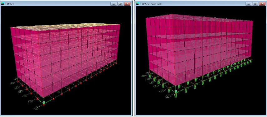
FIXED AND ISOLATED BASE BUILDING DRAWN IN ETABS SOFTWARE
Fig.1 Fixed base Building Fig.2 Isolated Base
284 | P a g e
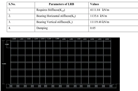
Table 1:INPUTS OF ISOLATORS AT BASE OF BUILDING:
S.No. Parameters of LRB Values
1. Requires Stiffness(Keff) 4111.84 kN/m
2. Bearing Horizantal stiffness(Kb) 1135.6 kN/m
3. Bearing Vertical stiffness(Kv) 11119.48 kN/m
4. Damping 0.05
Fig 4: REPRERENTATION OF ISOLATOR IN TYPICAL FRAME NETWORK
5.1. Equivalent Static Load Method
Earth Quakes are dynamic in nature and they change in magnitude time to time. We cannot predict these motions as they vary from locations.
The seismic code depends on the parameters such as Zone factor and Period of the structure. The basic assumption in this method is inertial forces are increased linearly as height increases. The distribution of loads depends on the first mode of response and may be modified accordingly.
5.2. Response Spectrum Method
A Response Spectrum is a curve plotted in between response of a single degree freedom and oscillator of varying period to a specific earthquake motion. It plots a graph between acceleration, Velocity or displacement response. By assuming damping, spectra may be generated in the structure. Code specifies the response based on soil type and Zone factor.
5.3. Time History Method
285 | P a g e
on past earth quake records we can get possible information regarding acceleration but every record has its unique values and we cannot predict these records to the upcoming earth quakes at the site.As we cannot predict earthquake at particular site with certain motion, we use time histories for foreseeable future of an upcoming earthquake.
TABLE 2:
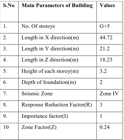
Input Parameters of Building
TABLE 3:INPUT PARAMETERS OF BUILDING S.No. Inputs of the Building Input Values
1. Wall Thickness(mm) 230 mm thick @ outer walls;150mm thick @inner walls 2. Beam Size(m*m) 0.5*0.3
3. Column size(m*m) 0.5*0.3
4. Materials Concrete(M25) and Reinforcement Fe 415 5. Depth of slab(mm) 150
6. Unit weight of concrete(KN/m3)
25
7. Unit weight of brick(KN/m3)
19.2
8. Unit weight of Tiles(KN/m3)
0.5
S.No Main Parameters of Building Values
286 | P a g e
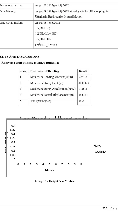
9. Response spectrum As per IS 1893(part 1):2002
10. Time History As per IS 1893(part 1):2002 at rocky site for 5% damping for Uttarkashi Earth quake Ground Motion
11. Load Combinations As per IS 1893:2002 1.5(DL+LL) 1.2(DL+LL+_EQ) 1.5(DL+_EL) 0.9*DL+_1.5*EQ
VI RESULTS AND DISCUSSIONS
Table 4: Analysis result of Base Isolated Building:
S.No. Parameter of Building Result
1 Maximum Bending Moment(kNm) 264.16 2 Maximum Storey Drift (m) 0.00073 3 Maximum Storey Acceleration(m/s2) 1.2516 4 Maximum Lateral Displacement(m) 0.0043 5 Time period(sec) 0.36
0 0.05 0.1 0.15 0.2 0.25 0.3 0.35 0.4
0 1 2 3 4 5 6 7 8 9 10
Ti
m
e
Per
io
d
(Sec
)
Modes
Time Period at different modes
FIXED
ISOLATED
287 | P a g e
0 0.2 0.4 0.6 0.8 1 1.2 1.4S T O R E Y 6S T O R E Y 5S T O R E Y 4S T O R E Y 3S T O R E Y 2S T O R E Y 1
ST
O
R
eY
A
C
C
EL
A
R
A
TIO
N
(m
/S
2)
STOREYS FIXED ISOLATEDGraph 2: Storey accelerations Vs No. of Storeys
0
0.00001
0.00002
0.00003
0.00004
0.00005
0.00006
0.00007
0.00008
ST
O
RE
Y
D
RI
FT
(m
)
STOREYS
FIXED
ISOLATED
Graph 3Storey Drift Vs No. of Storeys
288 | P a g e
VII CONCLUSION
For base isolated building Response have been increased from 0.26sec to 0.36 sec. Since the super structure will be subjected to lesser earthquake forces, the cost of isolated structure will be cheaper.
This specific provision of stiffness attracts lesser seismic forces and thus resulting double benefits compared to conventional structure i.e. reduction of axial forces from 3756.03 to 3441.8kN.
Storey drift will also be reduced by using isolators i.e. from 73 mm to 52 mm.
The emerging architectural designs are mostly irregular in geometry which leads to torsional and differential moments in X and Z directions. This may cause overstress to the frames. This can be overcome by provision of Base Isolator in the form of lead.
A base-isolation system reduces Ductility demands on a building, and minimizes its deformations.
Base isolation increases the flexibility at the base of the structure which helps in Energy Dissipation due to the horizontal component of the earthquake.
Hence the better fitted isolator based on the requirement is constructed economically to ensure Safe structure withstanding damages due to natural calamities.
REFERRENCES
[1].Islam ABMS, Ahmad SI (2010). Isolation System Design for Buildings in Dhaka: Its Feasibility and Economic Implication. Proceedings of the International Conference on Engineering Research, Innovation and Education. SUST. 11-13 January; Bangladesh, Sylhet. pp. 99-104.
[2].Balkaya C, Kalkan E (2003). Nonlinear seismic response evaluation of tunnel form building structures. Comput. Struct., 81: 153-165.
[3].Bhuiyan AR, Okui Y, Mitamura H, Imai T (2009). A rheology model of high damping rubber bearings for seismic analysis: Identification of nonlinear viscosity. Int. J. Solids Struct., 46: 1778-1792.
[4]. Matsagar VA, Jangid RS (2004). Influence of isolator characteristics on the response of base-isolated structures. Eng. Struct., 26: 1735- 1749.
[5]. Casciati F, Hamdaoui K (2008). Modelling the uncertainty in the response of a base isolator. Probabilistic Eng. Mechanics. 23: 427- 437.
[6].Yegian M.K.&Kadakkal U.- Foundation isolation for seismic protection using a smooth synthetic liner. Journal Of Geotechnical And Geoenvironmental Engineering © Asce / November 2004 /1123Bowman, M., Debray, S. K., and Peterson, L. L. 1993. Reasoning about naming systems.
[7].Kilar V, Koren D (2009). Seismic behaviour of asymmetric base isolated structures with various distributions of isolators. EngStruct., 31: 910- 921.