97 | P a g e
REPLACEMENT OF HUMPS METHODOLOGY BY
IMPLEMENTING SPEED CONTROL USING GPS
TECHNOLOGY
T. Divya
1, B. Santhosh Kumar
2, G. Ravindranath Kumar
31
Pursuing M.Tech (ES),
2
Assistant Professor,
3P
rofessor
1,2,3
Visvesvaraya College of Engineering and Technology
Patelguda, Ibrahimpatnam, Ranga Reddy, Dist. Telangana, (India)
ABSTRACT
Now a day’s road facility square measures a significant concern within the developed world. Recent studies show that one third of the quantity of fatal or serious accidents square measure related to excessive or
inappropriate speed, also as changes within the route (like the presence of road-work or sudden obstacles).
Reduction of the quantity of accidents and mitigation of their consequences square measure an enormous
concern for traffic authorities, the automotive business and transport analysis teams. One necessary line of
action consists within the use of advanced driver help systems.
The analysis target unifying the worldwide Positioning system with embedded wireless system is that the new
approaches in intelligent vehicle management for vital remote location application victimization ARM. In
typical system they're designed to manage the speed of vehicles altogether days. The most objective of the
projected system is to manage the speed of auto at vital zones. The bottom station having the transmitter that is
intended for modulation (FM), the receiver half is enforced in Vehicle. The ARM processor is enforced at
receiver facet, that receives the vital frequency, and so it's activated in vital mode. Speed management Driver
(SCD) is bespoke to suit into a vehicle’s dashboard, and displays data on the vehicle. Once the knowledge is
received, it mechanically alerts the motive force, to scale back the speed in keeping with the zone. The novel
system is enforced with the support of embedded processor and also the simulation is achieved through KEIL C
code and results square measure mentioned.
Keywords: ARM7 board, GPS, module, LCD, DC motor
I. INTRODUCTION
Now a day’s road facility is a major concern in the developed world. Recent studies show that one third of the
number of fatal or serious accidents are associated with excessive or inappropriate speed. In this project we are
implementing the GPS enable speed control system. The main aim of this project is to control the speed like
vehicles at the critical zones.The vehicle having the receiver and the base station having the transmitter
.whenever the transmitted signal was received by the vehicle at vehicle then automatically the speed of the
98 | P a g e
processor means our project kit is implemented at receiver side, which receives the critical frequency, and thenit is activated in critical mode. Then then speed of the vehicle automatically Reduce.
II. EXISTING SYSTEM
Up to now we use the vehicle breaks to reduce the speed but some of the driver they didn’t use the breaks for
that a lot accidents occurring, and some places they used the speed breakers at critical zones to reduce the speed
of the vehicle still with that also not great use so to avoid that we are using the “GPS enable speed control system”. In this project the transmitter at the critical zone side and receiver fixed to the vehicle whenever the
vehicle was entered into that particular location the vehicle will slow down up to crossing that critical zone,
after that the vehicle will automatically moves to according to speed.
III. PROPOSED SYSTEM
The main objective of the proposed system is to control the speed of vehicle at critical zones.The vehicle having
the receiver and the base station having the transmitter .whenever the transmitted signal was received by the
vehicle at vehicle then automatically the speed of the vehicle will automatically reduce. After crossing the
critical zone the vehicle moves in normal speed. The ARM processor is implemented at receiver side, which
receives the critical frequency, and then it is activated in critical mode
Block Diagram
Fig1: Block diagram
POWER
SUPPLY
LPC2148
MICROCONTROLLER
16x2 LCD
MAX232
L293D
DC Motor
GPS
MODULE
99 | P a g e
IV. HARDWARE REQUPIREMENTS
4.1 LPC2148 MICROCONTROLLER:
The ARM7 (advanced RISC machine) pressers board primarily based whole on a 16/32-bit ARM7
its method of 16/32-bit ARM7 TDMI-S microcontroller, 8 computer memory unit to forty computer memory
unit of on-chip static RAM and 32 computer memory unit to 512computer memory unit on-chip flash memory;
128-bit In- system Programming (ISP). 32-bit timers/outside event counters, PWM pulse width modulation unit
(six outputs) and watchdog, Low strength of actual-Time Clock (RTC), more than one serial interfaces which
has 2 UARTs , rapid I2C-bus (400kbit/. There are sixty four pins of ARM7 processer and 2 ports (port0, port1)
45 pins are input/output.
Fig2:-LPC2148 board
4.2 GSM-Module
GSM (international device for cellular communications) is a cell network, which means that that cell telephones
connect with it via way of searching for cells in the immediately place. GSM networks feature in four specific
frequency levels. Maximum GSM networks feature within the 900 MHz or 1800 MHz bands. A few
international locations in the Americas use the 850 MHz had been already allotted. Different bands are assigned
100 | P a g e
Fig 3: GSM module
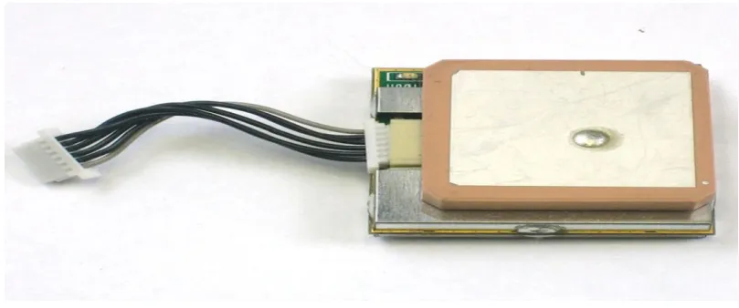
4.3 GPS
The Global Positioning System (GPS) is the only fully functional Global Navigation Satellite System (GNSS).
The GPS was used for the constellationbetween Earth Orbit satellites. That transmits microwave signals, which
enable GPS receivers to determine their location, speed.Global Positioning System is an earth-orbiting-satellite
based system that provides signals available anywhere on or above the earth. In this project the transmitter at the
critical zone andreceiver to the vehicle. When the vehicle enters into the critical zone the speed of the vehicle
automatically reduces.
Fig4: GPS module.
4.4 L293D
The L293D is a quadruple high-current half-H drivers, it also called as line driver circuit.The L293d is designed
to providebidirectional drive currents of up to 1 A at voltages from 4.5 V to 36 V. the driver contains totally 16
pins, in that four pins for input and four pins for output. The output pins are connected to the motors and input
pins are takes from the controller and l293d contains two power supply pins and two ground pins. The main use
of the l293d IC is to boot up the voltage levels to run the D.C motor. Here we are taking the four input pins and
four output pins, the D.C motor requires only two pins so we can run two motors at a time by using the l293d
101 | P a g e
4.5 MOTORS
Motors are electro mechanical devices which are used for to convert the electrical signals into mechanical
signals. The all D.C motors are having same internal mechanism, either electromechanically to change the
direction of current flow in part of the motor. In project we are used for to move the motor in specific direction.
We need to connect the motor to controller through driver IC only.
Fig4: DC motor
V. SOFTWARE DESIGN
In this proposed contrivance, as we tend to used LPC2148 we wish to use following software package
instrumentation to program for it.
1. Keil4 Vision
2. Flash Magic
The Keil4 Vision an IDE for Embedded c language. In this IDE, we wish to import the utilities and libraries
consistent with the controller. This IDE is very more easily and in user friendly thanks to apply, assemblers,
and debuggers in it. It simplifies the manner of embedded simulation and trying entering conjunction with Hex
file technology.The flash magic is a programming utility. The C/C++ software written in IDE could be
processed into Hex document i.e. in .hex layout. By using hex file we tend to merchandise the code into
microcontroller and perform application.
VI. WORKING PROCEDURE
Now a day’s road facility square measures a significant concern within the developed world. Recent studies
show that one third of the quantity of fatal or serious accidents square measure related to excessive or
inappropriate speed, also as changes within the route (like the presence of road-work or sudden obstacles).
Reduction of the quantity of accidents and mitigation of their consequences square measure an enormous
concern for traffic authorities, the automotive business and transport analysis teams. One necessary line of
action consists within the use of advanced driver help systems.
The analysis target unifying the worldwide Positioning system with embedded wireless system is that the new
approaches in intelligent vehicle management for vital remote location application victimization ARM. In
typical system they're designed to manage the speed of vehicles altogether days. The most objective of the
projected system is to manage the speed of auto at vital zones. The bottom station having the transmitter that is
102 | P a g e
receiver facet, that receives the vital frequency, and so it's activated in vital mode. Speed management Driver(SCD) is bespoke to suit into a vehicle’s dashboard, and displays data on the vehicle. Once the knowledge is
received, it mechanically alerts the motive force, to scale back the speed in keeping with the zone. The novel
system is enforced with the support of embedded processor and also the simulation is achieved through Keil C
code and results square measure mentioned.By using this project we can reduce the speed of the vehicle at the
critical zones. The vehicle have the receiver and at the critical zones it will have the transmitter whenever the
receiver receives the transmitted signal from the critical zones the vehicle speed will reduces. That means the
vehicle enters into the critical zone, passing of critical zone the vehicle will moves normal speed. The speed of
the vehicle will be reduces by the PWM technique.
VII. RESULT
Here the output of the project “”output was successfully implemented. The receiver fixed to the vehicle and
transmitter at the critical zones whenever receiver received the transmitted signal from the critical zone the than
vehicle will automatically reduce speed that implemented successfully.
VIII. CONCLUSION
By using this project we can conclude that when vehicle was enters into the critical the speed of the vehicle will
automatically reduce and after the critical zone the vehicle moves with normal speed. With this project we can
reduces the accidents at the critical zonesand we can reduces the speed of the vehicle from rash driving.
REFERENCES
[1] www.ijcsit.com/docs/Volume%204/Vol4Issue6/ijcsit2013040653.pdf
[2] www.google.co.in/patents/US5485161
103 | P a g e
[4] www.indjst.org/index.php/indjst/article/view/93045[5] https://en.wikipedia.org/wiki/Vehicle_tracking_system
[6] https://en.wikipedia.org/wiki/Global_Positioning_System
[7] www.mycollegeproject.com/ECE_Projects.html
[8] www.colorado.edu/geography/gcraft/notes/gps/gps_f.html
[9] www.montana.edu/gps/understd.html.
[10]https://www.cfa.harvard.edu/space_geodesy/ATLAS/gps.html
AUTHOR DETAILS:
T. DIVYA, Pursuing M.Tech (ES ) from Visvesvaraya College Of Engineering And
Technology, Patelguda, Ibrahimpatnam, Ranga Reddy dist. telangana, INDIA.
B.SANTHOSH KUMARworking as Assistant Professor from Visvesvaraya College Of
Engineering And Technology, Patelguda, Ibrahimpatnam, RangaReddy dist.,
telangana, INDIA.
G.RAVINDRANATH KUMAR (HOD), working as Professor from Visvesvaraya
College Of Engineering And Technology, Patelguda, Ibrahimpatnam, RangaReddy