Instructor
An SDN Platform for Traffic Offloading
Yanhe LiuHelsinki April 27, 2015
UNIVERSITY OF HELSINKI Department of Computer Science
Faculty of Science Department of Computer Science Yanhe Liu
An SDN Platform for Traffic Offloading Computer Science
April 27, 2015 88 pages + 88 appendices
traffic offloading, software-defined networking, WiFi networks, cellular networks
Cellular networks are facing a data explosion posed by the increasing bandwidth demand of current mobile applications, and cellular operators are trying to leverage auxiliary networks and offload mobile data for relieving this challenge. However, traffic offloading without comprehensive con-trolling may result poor network utilization and undesirable user experience. In this thesis, we design and implement an integrated architecture for intelligent traffic offloading over collaborative WiFi-cellular networks. Motivated by our measurement, we formulate a mathematical model to es-timate and evaluate potential offloading throughput based on various wireless context information, like AP signal strength and bandwidth. To efficiently manage traffic and collect information, we use a centralized SDN architecture in our design. The proposed system enables mobile devices to choose the most beneficial AP for offloading. The experimental evaluation of our prototype imple-mentation demonstrates that this architecture can achieve optimal traffic offloading by considering different real factors instead of making naive decisions. This effort not only explores the feasibility of context-based traffic offloading, but also provides guidelines for designing and implementing a centralized SDN platform for wireless networks.
Tekijä — Författare — Author
Työn nimi — Arbetets titel — Title
Oppiaine — Läroämne — Subject
Työn laji — Arbetets art — Level Aika — Datum — Month and year Sivumäärä — Sidoantal — Number of pages
Tiivistelmä — Referat — Abstract
Avainsanat — Nyckelord — Keywords
Säilytyspaikka — Förvaringsställe — Where deposited
Contents
1 Introduction 1
2 Traffic Offloading 4
2.1 Background and Motivation . . . 4
2.2 Cellular Data Offloading . . . 5
2.2.1 Wiffler: Augmenting Mobile 3G by Using WiFi . . . 5
2.2.2 MADNet: An Energy-Aware Offloading System . . . 7
2.2.3 MultiNets: Real-Time Interface Switching . . . 9
2.2.4 Other Techniques . . . 12
2.3 Load Balancing in Wireless LANs . . . 13
2.3.1 DenseAP: A Centralized Enterprise WiFi Network . . . 13
2.3.2 Dyson: A Client-Cooperated Extension of DenseAP . . . 16
2.4 Research Problems . . . 17
3 Software Defined Networking 20 3.1 Background . . . 20
3.2 OpenFlow: An Enabler of SDN . . . 21
3.3 SDN: Concepts and Structures . . . 23
3.4 SDN Controllers . . . 24
3.5 Towards Better Scalability . . . 26
3.6 SDN and Wireless . . . 29
3.7 Summary . . . 34
4 Design SDN-Based Offloading 35 4.1 Measurement Study Motivated by Offloading . . . 35
4.1.1 Throughput and Energy Consumption in Different Networks . 35 4.1.2 Number of Accessible WiFi APs . . . 39
4.1.4 Client Competition Interference on One WiFi AP . . . 44
4.1.5 Summary of Measurement Study . . . 46
4.2 Offloading Design . . . 46
4.2.1 Design Objectives . . . 46
4.2.2 System Design Principles and Architecture . . . 48
4.2.3 Communication Protocol Design . . . 49
4.2.4 Offloading Decision Making . . . 51
4.2.5 Other Possible Applications . . . 56
4.3 Summary . . . 56
5 Platform Implementation and Evaluation 58 5.1 Platform Implementation . . . 58 5.1.1 Central Controller . . . 58 5.1.2 Local Agents . . . 60 5.1.3 Client Extension . . . 62 5.1.4 Communication Protocol . . . 63 5.1.5 Realizing Offloading . . . 67 5.2 Evaluation . . . 69 5.2.1 Testbed Description . . . 70
5.2.2 Static Offloading Evaluation . . . 70
5.2.3 Mobility Prediction Evaluation . . . 76
5.2.4 Controller Overhead . . . 78
5.2.5 Client-Side Overhead . . . 80
5.3 Discussion . . . 82
6 Conclusion and Future Work 83
1
Introduction
Recently, we are experiencing an explosion of mobile data traffic attributed to a large growing number of mobile-connected devices and data consuming applications. According to Cisco’s recent report [Cisco14], global mobile data traffic has reached 1.5 exabytes (1.5 billion gigabytes) every month at the end of 2013, which grew nearly 80 percent during 2013. As an illustration, Cisco predicts that the global mobile data traffic will increase 11 times between 2013 and 2018, and the monthly traffic will surpass 15 exabytes by 2018. The main drive behind this considerable growth is the explosive increase in smart mobile devices and new mobile applications. As reported, there were over 526 million new mobile devices and connections added in 2013, and mobile video traffic has exceeded 50 percent.
To support this increasing traffic in mobile networks is quite challenging. One possible solution is to upgrade current network capacity. Nowadays operators are rolling out their next-generation networks such as LTE (Long Term Evolution) and WiMax to increase average cellular bandwidth. However, this may not promise an economical result both for users and operators. Even in 4G networks, bandwidth is still a limited resource under a flat price structure. When users are paying flat rates for data usage, the operators cannot obtain more from customers for extra data consumption. It is hard to balance end-user requirements and upgrading investments as well as operating costs of cellular networks.
Another feasible solution for this explosive traffic is offloading mobile data to aux-iliary networks. For example, offloading traffic from cellular to WiFi can reduce mobile data in cellular networks, and may gain better performance. For operators, it is extremely cheaper to build more WiFi hotspots than cellular network upgrad-ing. In addition, current networks have provided a superb environment for WiFi offloading. For instance, more and more organizations have already deployed a lot of WiFi access points (APs), which means users can easily find an auxiliary WiFi spot to transmit mobile data. As reported by Cisco [Cisco14], 45 percent of mobile data was offloaded to a fixed WiFi or femtocell network in 2013, and they predicts that the percentage will continue to increase.
Because of the economical benefits and potential, researchers proposed some mo-bile offloading schemes over WiFi or opportunistic networks. For example, Wiffler [BMV10], an early attempt on vehicular networks, makes offloading from cellular networks to WiFi networks. MultiNets [NNH+14] is another mobile offloading
ex-tension which evaluates WiFi offloading destinations mainly based on their signal strength and connectivity status. In addition, there are some other offloading sys-tems mainly designed based on a DTN (Delay Tolerant Network) approach (e.g. MoSoNets [HHK+12]), which exploit offloading scenarios where applications do not immediately require real-time data transmission. However, those schemes are only designed and operated with limited knowledge of networks, and may result bad transmission performances after offloading. For example, Wiffler and MultiNets only make offloading decisions based on historical bandwidth records and signal strength, but these kinds of information cannot reflect the present traffic load of a certain AP. If mobile users only use those types of data to make offloading decisions, there are high chances that their choices are non-beneficial, or even harmful. To address this problem, we present a new platform for traffic offloading with a global network view. This platform is based on a software-defined-networking (SDN) ap-proach, where cellular and wireless resources are managed by a centralized controller implemented on Floodlight1. In SDN, the network control plane is decoupled from the physical devices with well defined programmable interfaces and a centralized global view of networks. This is just what we require in a traffic offloading system: data traffic is controlled and monitored by a central controller, and offloading de-cisions are made based on the information gained by the controller. Our platform can handle mobile data offloading from cellular to WiFi networks, and also achieve dynamic bandwidth and user allocation among WiFi networks. In addition, this platform takes into account the challenges of wireless mobility and software porta-bility, and implements a general wireless local agent based on Click Modular Router [KMC+00].
The research work is driven by a measurement-based methodology. To design a practical traffic offloading system, we first conduct several different measurement experiments on WiFi and cellular networks. Motivated by those real-world measure-ment results, we design a context-based offloading decision algorithm in our system, formulate a mathematical model to estimate and evaluate offloading throughput, and implement a prototype platform to verify its feasibility. The evaluation shows that our proposal system may achieve optimal offloading by considering different real factors, and avoid non-beneficial offloading decisions.
The rest of this thesis is organized as follows. Chapter 2 provides an overview of traffic offloading. Chapter 3 describes some fundamental concepts and background
1Floodlight.
knowledge on SDN, and introduces some existing mobile and wireless SDN systems. The design idea of our SDN platform is explained after a measurement study in Chapter 4. Chapter 5 illustrates important implementation details of our platform, and presents testing results obtained from an evaluation of this platform. Finally we conclude this thesis in Chapter 6.
2
Traffic Offloading
In this chapter, we focus on the problem of traffic offloading, and review its back-ground and some related research work. In addition to cellular data offloading techniques, we extend our topic to re-association based wireless load balancing, and consider it as a subfield of traffic offloading.
2.1
Background and Motivation
Current cellular networks are overloaded with explosive traffic generated by increas-ing mobile devices and various bandwidth-consumincreas-ing smartphone applications (e.g., video streaming applications, like YouTube, which demand high network through-put). Reported by Cisco [Cisco14], there were 406 million new smartphones added into networks in 2013, and the average amount of traffic used by every smartphone has increased to 529 MB per month. It is forecasted that the number of mobile-connected devices will exceed the number of people on earth by the end of 2014, and the average traffic generated by smartphones will reach to 2.7 GB per month by 2018, which is 5 times more than today’s average load (539 MB).
To solve this explosive traffic growth problem, the most straight-forward solution is to scale the network capacity by upgrading cellular systems. As we state in chapter 1, many network operators are promoting their new-generation cellular networks like LTE and WiMax. However, simply increasing network speed may not always be economically effective. Bandwidth resources may still be limited even in 4G networks due to increasing user demand, let alone large investments and operating costs for upgrading the whole networks.
Instead of simply upgrading network capacity, offloading mobile data to auxiliary networks (e.g. WiFi networks) seems to be a feasible solution which can be quickly implemented at this moment. We have described that mobile offloading via WiFi is a very promising area both in research and industry fields in chapter 1. It is significantly cheaper to deploy new WiFi access points than cellular network up-grading, not to mention that many users have already installed their own WiFi APs at home or office. As illustrated by Lee Kyunghan et al. [LLY+10], we are living
in an environment with great WiFi connectivity. In their experiment, users may have available WiFi connections for more than 60% time of a day, and at any time, nearly 70% of users stay in a WiFi coverage area, which means users can easily find an auxiliary WiFi spot for data offloading. They also make some trace-driven
simulation, and show that WiFi is able to offload about 65% of the total mobile data with their data, and save 55% of battery power without delaying transmission. In addition to mobile data offloading, there is another type of traffic offloading scenario: re-association based WiFi load balancing. In conventional IEEE 802.11 wireless LANs (WLANs), clients select and associate with access points only based on local information like signal strength, which may lead unevenly-distributed traffic loads and poor performance [BC03]. For example, clients in a conference room tend to select the same AP with the best signal level and may suffer traffic congestion, while other adjacent APs may carry very light loads. To address this problems, researchers propose many different schemes to dynamically balance the load across multiple WiFi APs and provide fair services to clients. Since clients may need to re-associate with other APs, it is similar to mobile data offloading where traffic is offloaded from cellular access points to other different access points.
2.2
Cellular Data Offloading
As one of the most important parts in traffic offloading, cellular data offloading is always a hot topic both in research and industry fields. Motivated by its economical potential and benefits, many different works are proposed for cellular data offloading.
2.2.1 Wiffler: Augmenting Mobile 3G by Using WiFi
Wiffler [BMV10] is a mobile offloading system mainly designed for vehicular net-works. As an early attempt, it does not only propose a feasible offloading technique, but also shows some important features which need to be taken into account in of-floading design. In general, the simplest policy for mobile ofof-floading via WiFi is to transmit data in WiFi networks when available and switch back to cellular networks when WiFi networks are not available. However, this simple policy may not work well for vehicular networks. As illustrated in their paper, the availability of WiFi is much poorer than that of 3G cellular networks in a moving vehicle. According to their test results, WiFi access is only available 11% of the time, while 3G access is able to work 87% of the time. This notably limits the traffic load that can be offloaded to WiFi networks. In addition, they find that the WiFi average through-put for vehicular users is much lower than 3G. If applications simply offload data via WiFi networks irrespective of packet loss rates, they will definitely hurt user experience.
To overcome these availability and performance challenges, Wiffler introduces some key techniques for data offloading:
1. Leveraging delay tolerance. According to their test, the availability of WiFi increase to 30% with 60-second intervals, which makes offloading from 3G to WiFi more feasible. Also, a user may be willing to tolerate a few seconds delay for sending emails or downloading a file if it can reduce cellular bandwidth usage. Instead of transmitting data immediately, Wiffler introduces delay timeouts, and waits for WiFi to send data before those timeouts.
2. WiFi throughput prediction. Before transmitting data via WiFi
connec-tions, Wiffler uses a simple method to predict future WiFi throughput, and offloads only if WiFi can really save 3G usage within the delay tolerance. It predicts the number of APs one user will meet in the next time interval based on the average number of meeting APs in the past interval, and estimates the average throughput for the future APs based on the historical throughput observed in the past interval. For example, if a user met 4 APs in the last 120 seconds, Wiffler predicts that it will encounter 2 APs in the future 60 seconds. This simple prediction scheme comes from the observation that APs are always densely located in the same areas. For example, if a mobile user met a lot of APs in the past 5 minutes, he/she is likely to continue to meet new APs in the next 5 minutes (perhaps because it is in a urban area with many APs, e.g. city center).
3. Quickly Switching from WiFi to 3G. Wiffler switches back to cellular
networks if WiFi is unavailable within a delay window. The functionality is implemented in a low-level program, which performs very fast.
Though Wiffler proposes a feasible way to offload data in vehicular networks, it may be not suitable for some other scenarios. As illustrated by Lee Kyunghan et al. [LLY+10], the average WiFi temporal coverage is much higher than 11%. In their experiment, the average temporal coverage of available WiFi spots for all day usage is about 70% per user. This huge difference may be caused by different measurement scenarios: Wiffler’s tests are done mainly by using war-driving, while Lee et al. focus on the natural mobility of users. Typically, a user does not stay inside a car or bus for quite long time, but spends a lot of time in office or at home, where the user is likely to have available WiFi access points.
2.2.2 MADNet: An Energy-Aware Offloading System
Different from Wiffler’s scheme which is only based on client-side information for offloading , Aaron Yi Ding et al. [DHX+13] propose a collaborative mobile data
offloading architecture which is mainly designed for extending mobile battery life. It does not only use a client module on mobile devices, but also introduces two proxy modules in both of WiFi networks and cellular access networks. The three components work collaboratively to decide when and how a client shall offload its cellular data to WiFi networks. Figure 1 shows the three major software components of MADNet.
Figure 1: Basic Structure of MADNet [DHX+13]
According to the authors’ measurements, mobile devices may consume more energy to transfer the same amount of data via a low throughput WiFi connection than that over a high speed 3G access. If applications simply offload as much data as possible via WiFi networks without considering throughput conditions and energy consumption, it may result a shorter battery life for a mobile device. To avoid bad decisions on offloading and selecting WiFi access points, Wiffler uses a simple scheme to predict future WiFi throughput, and if the prediction shows a bad throughput potentially, Wiffler tries to use cellular networks instead. However, it is probably inaccurate since Wiffler only uses historical average throughput to predict future bandwidth for different WiFi access points which may be totally unrelated.
In MADNet, a mobile client first sends its location and mobility information to the corresponding cellular proxy when it wants to fetch contents from the Internet. Then the cellular proxy determines whether the mobile device can potentially save energy by offloading cellular data to a given WiFi AP. If the offloading is determined
to perform, the proxy also notifies the candidate WiFi proxy to pre-fetch contents. All the computational tasks on evaluating offloading candidates are moved to the cellular proxy. Since the proxy knows the client’s location and neighboring WiFi APs, it may give a better choice on offloading. After receiving the offloading decision and the information about the objective WiFi AP, the mobile client can switch to WiFi networks and continue downloading.
MADNet only performs WiFi data offloading when it predicts that receiving data from WiFi APs saves more energy than transmitting them via cellular networks. It also takes into account the extra energy consumption caused by WiFi offloading and interface switching. For making offloading decisions, MADNet mainly uses the following model to decide whether it is beneficial to offload to a specific WiFi AP:
ET +P3G·CW/B3G−PW ·CW/BW > k·Eoo
and if this inequality holds, it will ask the client to offload to this AP, or otherwise it will continue to check other WiFi APs.
1. ET is the head and tail energy consumption for mobile devices. Typically,
a 3G interface resumes staying at high power after transmitting or receiving a packet, and then drops back to low power only after it has been idle for few seconds. This kind of power consumption caused by state transition is represented as ET here.
2. P3G ·CW/B3G shows the energy consumption if it downloads a file via 3G
cellular networks. P3Gis the transmitting power of 3G interface, andCW is the
size of the desired file. B3G is a predicted throughput value of 3G networks,
which can be estimated from the historical maps between throughput and location.
3. PW ·CW/BW represents the estimated energy consumption if the download
goes through WiFi networks. Similarly to cellular energy consumption, BW is
a estimated throughput value of a specific WiFi access point. MADNet can calculate this value from devices’ historical mobility and throughput records. 4. k·Eoo. Eoo is the offloading related overhead, andkis a constant for
accommo-dating measurement errors. Typically, this shows the extra power consumption caused by offloading.
In general, this model compares the power consumption of cellular networks and WiFi networks, and check whether offloading can bring more energy saving when the overhead is also considered. Based on this algorithm, MADNet may avoid to offload mobile data to low-throughput WiFi networks.
2.2.3 MultiNets: Real-Time Interface Switching
MultiNets is a seamless offloading system that is mainly designed for real-time net-work switching [NNH+14]. It focus on seamless interface switching, which is quite
different from Wiffler and MADNet that we introduced before. MultiNets enables a mobile device to automatically switch to the most suitable network interface based on user-defined policies (energy saving, data offloading, or performance) without interrupting running applications. Real-time here stands for switching network in-terfaces in real time without delay. Unlike Wiffler, MultiNets does not introduce delay tolerance for offloading.
Seamless offloading from one wireless interface to another is not as easy as it seems to be. Simply turning off the old interface and turning on a new one may result connection interruption and data loss, which probably hurts user experience when they try to load web pages or play online games. In addition, it may be more challenging to switch connection-oriented data from one interface to another without interruption. For example, an established TCP connection will be closed if the interface being used is turn off, and if we try to use a new interface to resume data transmission, we have to re-initialize new TCP sessions.
To address challenges of seamless offloading, MultiNets proposes a interface switch-ing mechanism mainly for TCP sessions without changswitch-ing current network proto-cols. This switching mechanism is designed based on some mobile traffic features concluded from a 3-month-long study, which shows that almost all (99.7%) mobile traffic is TCP, and the average lifetime of TCP sessions is about 2 seconds, as well as the average concurrency of active sessions is smaller than 2. These features of short lifetime and low concurrency means that we can remain ongoing TCP sessions in the old interface until they finished before finally switching:
1. MultiNets counts and records the total number of ongoing TCP connections on the old interface before offloading starts.
2. If there is any ongoing TCP session, MultiNets first adds new routing table entries for all of them by explicitly specifying to still use the old interface.
This makes sure that the ongoing TCP sessions remain working via the old interface.
3. Then Multinets turns on the new interface, add new routing table entries for it, and replace the default gateway with the new interface. From now on any new connections will be sent via the new interface.
4. MultiNets waits for a given timeout before tearing down the old interface. It tries to resume these connections without interrupting them during switching. Finally it completely moves on to the new interface.
MultiNets is designed and implemented on the Android platform. It consists of three foundational components: Switching Engine, Monitoring Engine and Selec-tion Policy. The switching engine is the main module which performs the switching between cellular and WiFi. The Monitoring Engine collects all the necessary param-eters for switching (e.g. how many TCP sessions are alive on the cellular interface, the amount of data transmitted and received over WiFi and cellular networks, and battery capacity). The Selection Policy defines how switching operates based on bandwidth and power factors. MultiNets provides three different policies right now by considering different scenarios.
• Energy-Saving: this policy is designed for minimizing mobile power consump-tion. Based on the authors’ measurements, they propose a heuristic switching algorithm. Mobile devices connect to cellular networks when they are idle, and MultiNets monitors how many bytes sent over cellular interfaces after ap-plications run. The devices will try to switch to WiFi networks as soon as the total amount of data over cellular networks exceeds a specific threshold. When devices are idle in WiFi networks for a certain period, they will switch back to cellular networks.
• Offload: this policy tries to offload as more data as possible via WiFi connec-tions. Devices will switch back to cellular networks if WiFi’s signal strength is very poor.
• Performance: the object of this policy is to provide better throughput over different networks. It compares different interfaces and networks by using estimated bandwidth values derived from corresponding signal strengths, and choose the better one to offload.
Since Android does not support this kind of dynamic network switching, the au-thors implement MultiNets in a layered style like Android by themselves and hope to provide a general model for various mobile systems. Classes and services of Multi-Nets are similarly layered as Android’s original modules. Figure 2 shows the layered implementation of MultiNets. As we can see, some native C/C++ modules that perform lower-level tasks like modifying routing tables are added in Android, and those modules are wrapped into Java API for upper-level applications. As shown in their trace-driven experiments, MultiNets can save up to 33% energy usage on An-droid platform in energy-saving mode, or achieving WiFi offloading while reducing TCP interruptions caused by interface switching.
2.2.4 Other Techniques
Besides offloading cellular data via WiFi networks, researchers also propose some dif-ferent techniques based on other complementary networks. Bo Han et al. [HHK+12] design and implement an offloading system based on opportunistic networks. Dif-ferent from WiFi networks or other networks with fixed infrastructure, there is probably no complete path to forward packets in an opportunistic network. Con-tents are delivered opportunistically in a store-carry-forward way with the help of human mobility, and device-to-device connections are widely used in opportunistic networks. For example, mobiles can forward data to other devices via bluetooth networks, and reduce mobile data traffic over cellular networks.
In the system proposed by Bo Han et al., mobile users can help to propagate data via opportunistic networks if they meet friends who are also interested in what they have received. Users share data and files within a peer-to-peer transmission range over Bluetooth or WiFi networks. The authors also introduce social participation to their system for enhancing data spreading. Service operators can first choose some active users to receive data through cellular networks, and those active users may have high chances to meet and disseminate data to their friends via opportunistic networks. Experimental results show that their system can reduce the amount of mobile cellular traffic by more than 50 percent with given data traces.
Rather than choosing one interface for global traffic in a mobile device, Brett Hig-gins et al. [HRA+10] propose a different offloading mechanism, which they call it
intentional networking. In their scheme, applications provide hints about their traf-fic semantics by giving some distinguished labels, and the system matches network traffic to the most suitable interfaces based on these labels. For example, game
applications may request high bandwidth connections with labels indicating large foreground traffic loads, and the system forward game data via a WiFi interface with better bandwidth. Different from other offloading schemes we explained in the previous sections, intentional networking selects different interfaces and networks for different applications.
To decide which interface is more suitable, they implement a specific process (called as "connection scout") for bandwidth monitoring and evaluation. The connection scout tries to establish network connections periodically over each wireless interface. If a connection is successfully established, it measures the throughput and perfor-mance of the corresponding interface. Later, the system chooses interfaces based on latest evaluation results from the connection scout.
2.3
Load Balancing in Wireless LANs
Re-association based load balancing, wherein traffic loads across multiple wireless APs can be balanced by dynamically re-assigning clients to different APs, is another kind of traffic offloading applications. There have been some research efforts on this topic. In general, we can group them into two categories: centralized controlling systems and distributed heuristic methods. Nowadays most of the IEEE 802.11 WLAN load balance techniques are using the centralized method in which a central controller makes re-association decisions for clients. The distributed schemes may be more flexible, but always introduce complicated computation tasks on mobile devices. In this section, we mainly focus on the centralized approach, and review some existing research work on it.
2.3.1 DenseAP: A Centralized Enterprise WiFi Network
DenseAP, proposed by Rohan Murty et al. [MPC+08] in 2008, is a centralized software architecture for enterprise WLAN deployments. It is designed for current enterprise WLANs where access points are deployed densely (e.g. there may be an AP in every office). To make better association decisions for clients in such an environment with several different available APs in one area, DenseAP system designs a centralized association controlling mechanism. The basic structure of DenseAP is shown in Figure 3. It consists of several programmable DenseAP nodes (DAPs) which act as WiFi access, and a DenseAP controller (DC) which is the central controller.
Figure 3: Overall Architecture of the DenseAP System – several DenseAP nodes are controlled by one DenseAP controller [MPC+08].
In conventional WLANs, clients make association decisions (select which AP to as-sociate with) only based on local information like signal strength. However, this may result in extremely unfair bandwidth allocation among mobile clients. To improve performance, clients need to connect to different APs even if some APs do not show the best signal strength. In DenseAP, a central controller is used for determining which AP each client shall associate with. As shown in Figure 3, each DenseAP node (DAP) periodically sends summary information about associated clients, cur-rent channel conditions and new client requests to the controller. All these periodic summaries sent by DAPs provide the controller with a global view of the whole net-work. Based on this global view, the controller may choose a suitable access point for each client, allocate channels and perform load balancing.
In current WLANs, clients have to first gather information about available access points before associating, and there are two ways to do that. The first method is called "active scanning", where clients send out Probe Requests on each channel. When APs receive Probe Requests, they will respond with Probe Response messages which include their SSID (Service Set Identification) and BSSID (Basic Service Set Identification). Instead of sending requests actively, clients can just wait for infor-mation messages from APs. Typically, APs advertise themselves by broadcasting Beacon frames periodically, and the Beacon frames are similar to the Probe Re-sponse frames. Clients just scan all the channels one by one, and listen for incoming Beacons. Once clients obtain necessary information from APs, it decides which AP to associate with mainly based on AP’s signal strength.
For instructing clients to choose suitable access points without any modifications to existing 802.11 protocols, DenseAP uses a "tricky" method to manipulate original WLAN management packets. In DenseAP, the controller performs association con-trol by exposing specific APs to clients selectively. First of all, access points in the DenseAP network do not send out any beacons or only send beacons with a hidden SSID. By doing this, clients have to send probe requests actively before association. Second, each AP in DenseAP maintains a local access control list (ACL) of client MAC addresses. When receiving a Probe request from a client, access points only replies to those whose MAC addresses are listed in the ACL. If an access point receives a request from an unrecorded client, it informs the controller, and the con-troller determines which access point shall respond to this client. Then, the chosen access point adds the client to its ACL, and sends replies to it. At any given time, one client’s MAC address is only recorded in one access point’s ACL, which means only one access point is visible to that client.
With this probe response controlling scheme, the association process in DenseAP runs like this: (i) A new clientAwith MAC addressXbroadcasts probe requests. (ii) Several different access points receiveA’s requests, and inform the central controller. (iii) The controller determines which AP the client shall associate with, and notify that AP to addX in its ACL (access control list). (iv) When the client send another probe request again, the chosen AP withX in its ACL responds to the request, and initializes an ordinary association process.
In the association process, the controller is responsible for determining which access point a client shall connect with. To pick the most beneficial access point, the controller in a DenseAP works as follows: first, the controller estimates potential throughput for the client on each different access point. This is a very challenging task since the expected throughput depends on several different factors. Instead of evaluating all these factors, DenseAP mainly focuses on two of the most important ones: transmission rateandfree air time, and uses these two metrics to calculate the overall available capacity for access points.
• transmission rate: since the transmission rate primarily depends on sig-nal level between clients and access points, DenseAP uses the sigsig-nal strength (RSSI) of probe requests sent by clients to estimate transmission rates on dif-ferent access points. When clients attempt to associate, they send out probe requests. Access points report those received requests to the central controller with their RSSI values, and the controller estimates the transmission rate for
each access point based on the RSSI value.
• free air time: this metric can be used to measure how busy an access point is. The amount of free air time around one access point depends on the traffic generated by this AP. For example, the free air time for one AP may be low when several clients are connecting to it and sending data via it. To calculate the free air time, each AP sends a small broadcast packet periodically at a fixed rate with its highest priority queue (packets in this queue are sent even if there are packets pending in other data queues), and records the delay before the packet is finally sent out from the queue. If the channel is busy, the delay time will be larger than the one caused only by common transmission overhead. Once the controller collects the transmission rate (denoted as R) and free air time (F) for each access point that receives probe requests, it calculates the available capacity: Capacity = R∗F, and picks the highest one as the AP for hosting the new client. If available capacities of several DAPs are equal, the controller picks the one that has the fewest clients associated with.
After reviewing how the association works in DenseAP, we can have a glance at how it performs load balancing, which is extended from the basic association process. The controller checks the utilization rate on each access point periodically. It uses the free air time to measure the utilization, and if the free air time of one access point is less than 20%, it is considered as an overloaded one. When the controller finds overloaded access points, it tries to move some clients on those APs to other idle APs. For example, if an access pointA is overloaded, for each clientc∈A, the controller attempts to find another access point (denoted asB) where the expected transmission rate m at B is better (or at least not worse) than that at A, and the free air time at B is at least 25% higher than that at A. If such access point is found, m is switched to B following the process described in the association part.
2.3.2 Dyson: A Client-Cooperated Extension of DenseAP
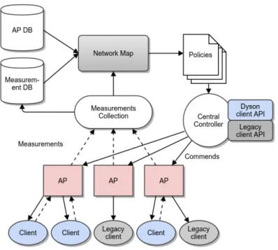
Dyson is a centralized software architecture for wireless networks [MPWW10]. It is extended from DenseAP where no client is involved in the software system. As shown in Figure 4, Dyson consists of a central controller, programmable access points, and two different kinds of clients: Dyson-enabled clients and legacy ones. Both APs and Dyson-enabled clients report measurements to the central controller, and the central controller generates a global view of the whole network based on
Figure 4: The Dyson Network Architecture – measurements are collected from un-derlying devices, and stored in specific databases. The central controller makes management decisions based on those measurement data [MPWW10]
those measurement data. Like some software-defined networking systems, this global view allows the controller to perform a set of management policies comprehensively. To have better utilization on measurement data, Dyson records them separately in specific databases.
Though Dyson extends WLANs in a software-defined approach, it still builds upon existing 802.11 standards. One key benefit of Dyson is that it can collect client-based measurements and provide the controller with a better network view. Moreover, legacy clients without the Dyson extension can still be used in Dyson only with reduced functions. Similar to DenseAP, Dyson supports to measure connectivity and channel airtime utilization for each APs. Furthermore, it can also record node locations with the help of Dyson-enabled clients.
2.4
Research Problems
After reviewing some existing work on traffic offloading, we realize that almost every method exposes some deficiencies, and suffers from one or more of the following limitations:
• Inefficient and incomplete offloading decision-making: as one of the most important part in traffic offloading, decision-making on offloading is stud-ied and explored in every research work we explained in the previous section. Typically an offloading system needs to make two crucial decisions: is it bene-ficial to offload traffic from one access point to another (or when is it benebene-ficial to do that)? Where shall the traffic be offloaded?
Although the previous research work provides different decision-making schemes, clients may still suffer from non-beneficial offloading decisions. For example, Wiffler determines whether to offload from cellular to WiFi networks only based on historical average throughput of past WiFi access points, which may provide totally unrelated and misleading information for future selection. Some other systems like MultiNets estimates bandwidth for future offloading access points only with their signal strengths. As we discuss before, this may lead very unfair decisions and bad performance. MADNet tries to compare the expected energy consumption in cellular networks and the ones in differ-ent WiFi networks, but the corresponding bandwidth values are still estimated from historical records without considering present traffic loads on each access point. Although DenseAP and Dyson try to measure this kind of real-time traffic loads on APs by introducing free air time, it may take several period to obtain an accurate value, and the suitable offloading time may have been missed.
• Lack of practicality: while previous studies have provided many different prototypes for traffic offloading, most of them are mainly designed to solve a part of the problem. Like Wiffler is only implemented for vehicular networks, and MultiNets simply provides algorithms for interface assignment. What we are looking forward to is a practical framework for traffic offloading as an overlay solution over current (or maybe future) cellular and wireless networks. Besides those limitations, some new features may also be required in a new traffic offloading system since seamless offload has been adopted and standardized by Inter-net Engineering Task Force (IETF) and the Third Generation Partnership Project (3GPP) as a technique in 3G networks.
• Collaborative management between both cellular and WiFi accesses:
as we mentioned, cellular data offloading and WiFi load balancing show sim-ilarities in many aspects (including the decision making, techniques for
real-time offloading, etc.), but there are few collaborative controlling systems be-tween cellular and WiFi networks. Most of the work we review in this section are only designed for either cellular offloading or WiFi load balancing.
• Extensibility: the system shall be extensible in order to support diverse needs for different networking scenarios. If the system is implemented via a software approach, it shall provide programming abstractions and extensible structures for future development.
• Context from users: mobile users can generate rich contexts with their
device sensors, and those contexts may be helpful for traffic management sys-tems. In MADNet and Dyson, users provide some information to the central controller for better offloading decisions, but it seems that we can use more. How can we utilize the rich contexts from mobile users to facilitate the offload-ing procedure?
3
Software Defined Networking
In this chapter we give a brief introduction to Software Defined Networking (SDN), which we use as a fundamental concept in our system design. Then we review and discuss some previous research work related to SDN.
3.1
Background
Nowadays, computer networks have become exceedingly complex. A large growing number of devices are connected into networks to provide various network services. For common customers, this is definitely good news because they can enjoy rich services, but for network operators and administrators, this is notably challenging. Due to current network architectures, deploying and setting up a large-scale network is anything but not a easy job.
Typically, a networking device (e.g. switch, router, firewall) is architecturally com-posed of a data plane and a control plane. The control plane decides how and where traffic is delivered by this networking device (which can be considered as the logical "brain" of the device), and the data plane is concerned to forward packets according to the policies defined by the control plane. For example, the policies in a switch’s flow table constitute the control plane, and the whole forwarding process can be regarded as the data plane (e.g. looks up destination addresses of incoming packets, determines paths by using the flow table, and delivers packets through the forward-ing fabric). As we can see, the control plane and data plane for legacy switches and routers are closely coupled together.
This integration of control plane and data plane may be beneficial for building a small network with few devices: simple forwarding policies can be easily defined on separated switches and routers, and quickly updated later. However, this may result in big challenges if the network scales to more than hundreds of devices and thousands of hosts. Since the controlling logic is integrated into underlying devices, nearly every device needs to be set up separately. Configuration and management are notably laborious in this scenario, let alone to update the whole network for global changes (e.g. IPv4 migrating to IPv6). The coupling of control logic and data forwarding also hinders innovation of computer networks. To experiment with new ideas and test new protocols in a real large network, researchers have to add complicated configuration carefully to avoid affecting other normal traffic.
In addition, legacy networks are managed through low-level configuration and device-various parameters (e.g. IP addresses and MAC addresses). It is similar to write programs in machine languages in the early days of computers: programmers had to consider everything with very low-level details, which made programs hard to write, port and maintain. Modern operating systems and programming languages have already solved this problems by providing high-level abstractions for low-level resources and information, but legacy networks are still lack common abstractions for underlying resources. Though we use layers to represent the networks, they are not enough for a large-scaled network where configuration and management involve thousands of nodes.
3.2
OpenFlow: An Enabler of SDN
In response to the problems we mentioned in traditional computer networks, re-searchers started to explore new network architectures. OpenFlow, first proposed as a short-term solution for programmable networks [MAB+08], enables to control
underlying devices in a software-based approach, and promotes future development on SDN.
OpenFlow defines a standardized way to separate the control and data plane, and provides programmable interfaces for remote management. In traditional networks, forwarding logic is bound to Ethernet devices. In OpenFlow, we can access and manipulate flow tables of Ethernet switches via specialized communication channels from a remote controller. As we can see from Figure 5, the logical controller is separated from OpenFlow switch.
Figure 5: Main Components of an OpenFlow Switch [OF13]
Header Fields Counters Actions
Table 1: Flow Entry in OpenFlow v1.0.0 [OF09]
Match Fields Priority Counters Instructions Timeouts Cookie Table 2: Flow Entry in OpenFlow v1.4.0 [OF13]
tables, which perform packet matching and forwarding, and an OpenFlow channel connected to a remote controller. Each flow table contains a set of flow entries with associated match fields, counters and instructions on matched packets. The remote controller can add, edit or delete flow entries in flow tables actively or re-actively (in response to packets and queries) via the standardized OpenFlow protocol. The basic flow entry for OpenFlow version 1.0.0 [OF09] is shown in Table 1. The header fields are used to match incoming packets; the counters record the number of matching packets; actions are the forwarding instructions to apply to matched packets. A flow entry of OpenFlow version 1.4.0 [OF13] includes more specific fields for supporting more detailed information and more complex operations, and it is displayed in Table 2.
In general, packets are processed by OpenFlow switches as the following steps: 1. Switches perform matching and lookup for every incoming packet according
to their flow tables, and if it is matched to one flow entry, the packet will be processed according to the actions defined in that flow entry.
2. One packet can be matched several times with different flow entries, and ac-tions will be performed sequentially according to the priority of each flow entry.
3. If no match is found, the switch will perform a default action (e.g. drop the packet, or forward it to a remote controller).
By introducing programmable flow tables and a standard controlling protocol, Open-Flow switches provide great flexibility to network management and configuration. The control logic and forwarding plane can be separated now with OpenFlow-enabled devices, and we can dynamically set up forwarding policies remotely and programmingly by using OpenFlow, which notably promotes future development of SDN.
3.3
SDN: Concepts and Structures
Before OpenFlow was released, researchers had proposed some different control mechanisms aiming to give a global abstract view of networks. For example, 4D [GHM+05] and SANE [CFP+07] are both early attempts for this kind of network abstraction. However, most of them lack general programmatic control of underlying networks. Thanks to OpenFlow, standardized network controllers and network op-erating systems with general programming interfaces are emerging, and the general concept of SDN becomes more clear.
SDN (Software Defined Networking) provides a revolutionizing networking architec-ture which moves control logic from underlying devices to centralized controllers. It suggests to build a network in a centralized approach instead of completely dis-tributed ones. In SDN, packet forwarding is controlled by a global controller via programmable interfaces. This is quite different from legacy networks where for-warding policies are bound into underlying devices. A typical SDN architecture is shown in Figure 6. Programmable forwarding devices (like OpenFlow switches) are in underlying networks. The upper network operating system provides an global and centralized view of resources in networks. A network virtualization layer may abstract the global view to higher level ones (e.g. represent network devices by us-ing human readable words instead of IP addresses and MAC addresses), and we can easily develop and maintain control programs based on those abstract views. Typically, SDN is designed with three most characterizing properties:
• Separating the control plane from the data plane: this logic decoupling may simplify network management and provide opportunities for future extension. • Providing applications with a global view of the network and a higher level of abstraction: compared with making decision distributedly, a global view helps controllers to make better choices. Also, it is easier to write management programs with a higher level of abstraction. Image how difficult it will be if you have to write your controlling programs with fixed IP addresses and MAC addresses, not to mention upgrade your programs when those physical addresses changed.
• Programmability: the control logic can be defined with software programs. This is one of the most important features in SDN. The first two properties (logic decoupling and abstraction view) also promote a better programming
Figure 6: Architecture of an SDN platform
style in SDN. Developers can write more dynamic and flexible controlling programs based on an abstract view of the network, which is much easier to maintain and upgrade in the future.
In general, SDN provides great opportunities to solve problems in current networks. It proposes a powerful way to set up network policies by using centralized con-trollers via programming interfaces, which may free network administrators from boring manual configuration with low-level device-based commands. In addition, it is more easier to introduce new ideas and run experiments in an existing network in a software-based approach.
3.4
SDN Controllers
As one of the most important parts in SDN, controllers (or sometimes regarded as network operating systems) are always the hottest topic in both research and industry fields. NOX, the first OpenFlow controller released in 2008 [GKP+08], is one milestone attempt of SDN controllers. After NOX, many other OpenFlow
controllers have been released, like POX2, Floodlight, and Ryu3. Figure 7 shows the basic structure of a NOX-controlled network, and most SDN systems follow a similar network architecture: a set of OpenFlow switches are connected to a centralized controller, where management applications run with a global view of the network. The network view is collected and updated by the centralized controller with OpenFlow switches, kept in a database, and used by different applications as their program inputs.
Figure 7: Architecture of a NOX-based Network – OpenFlow switches, a server running NOX and management applications [GKP+08].
NOX and many other controllers use standardized events to represent incoming changes happened in underlying networks (e.g. links go up and down, flows arrive and leave). Applications can register specific event handlers to cope with particular changes. When those events happens, logic in corresponding event handlers will be triggered. We show this basic handling process in Figure 8 with Beacon [Eri13], a Java-based SDN controller. The controller collects OpenFlow protocol messages, and sends those information to applications registered with a specific OpenFlow monitor service. Then those registered application listeners receive updated messages in a serial pipeline. For example, in Figure 8, the application "Device Manager" first
2Pox. http://www.noxrepo.org/pox/about-pox/ 3Ryu. http://osrg.github.io/ryu/
obtains OpenFlow messages, then it can propagate those messages to the "Topology" application. In this way, underlying events can be easily propagated to different applications.
Figure 8: Beacon OpenFlow Signal Handling Pipeline [Eri13]
In general, the central controller is responsible to collect information from underlying devices, and generate a global view of the network. Extended applications running on the top of the controller use the global view (or a part of the view) to make management decisions, and perform various networking policies.
3.5
Towards Better Scalability
With the development of SDN techniques, researchers start to focus on network scaling. The main initial purpose of a SDN controller is to offer a centralized and abstract view of underlying networks, and increase the productivity for network management and configuration via a software-based approach. However, achieving this transformation from a completely distributed system to a centralized archi-tecture brings considerable challenges of scalability. It is difficult to manage lots of resources only in a centralized way when the size of a network grows. Also, performance can be a bottleneck for a centralized system. For example, if all the underlying switches need to communicate with one central controller, some of them may suffer long latencies if they are far away from the controller in a very large network. For scaling existing SDN systems, researchers have proposed some new structures and techniques for SDN controllers.
Kandoo: A Hierarchical Control Platform
Kandoo is a hierarchical SDN framework designed for the OpenFlow protocol [HYG12]. It introduces a two-level hierarchical SDN controlling architecture, and separates lo-cal configuration and management from global policies. It creates a simple extension for scaling SDN systems: local controllers directly manage OpenFlow switches and execute applications which do not require network-wide views, while a root con-troller with the global view is responsible for all the underlying local concon-trollers.
Figure 9: Kandoo’s Two-Level Framework – local controllers process frequent and local events, whereas a root controller handles other global events [HYG12].
Figure 9 illustrates this hierarchical framework. For event handling, Kandoo follows the similar idea used in NOX and beacon, and extends it in a two-level hierarchical system. The root controller can subscribe a set of specific events in local controllers, and the local controllers will propagate those events to the root controller when they happen.
HyperFlow: Extending NOX to Distributed Controllers
Different from Kandoo’s hierarchical centralized framework, HyperFlow proposes a logically centralized but physically distributed SDN controlling system [TG10]. It allows more than one controllers to be deployed in a network, and every controller shares a consistent network-wide view. This structure provides both scalability and control centralization for a SDN system.
HyperFlow network consists of a set of OpenFlow switches as forwarding plane, sev-eral NOX servers running the HyperFlow controlling application as distributed con-trollers, and an event spreading system for controller communication and synchro-nization. All the controllers run the same software and have a consistent network-wide view. OpenFlow switches are connected to the best (nearest) controller with shorter response time. If one controller crashes, switches can be logically moved to another controller nearby. Figure 10 shows the basic structure of a HyperFlow network.
Synchronizing network views is the most distinguishing feature of HyperFlow. It provides a consistent network view by using a event publish/subscribe component. Each controller running HyperFlow publishes traffic/controlling events which are generated locally but affect the global network view to other controllers. In the mean time, other controllers can subscribe those messages from specific communication
Figure 10: Overview of HyperFlow – the HyperFlow application runs on each NOX controller, and each controller synchronizes events and controlling logic with other controllers via specific channels [TG10].
channels, and replay them for generating a consistent network view. In addition, HyperFlow introduces health checking to SDN controllers for better reliability. Each HyperFlow controller sends advertisements periodically to indicate its state and health. If one controller does not publish those advertisements for several successive intervals, it will be considered as crashed, and the switches which were managed by it will be logically redirected to other neighboring healthy controllers.
Onix: A More Flexible Distributed Controlling Platform
Onix is another distributed SDN controlling framework. It creates a distributed data structure called NIB (Network Information Base) to represent network resources. In NIB, each network element is recorded as a set of key-value pairs with a globally unique identifier. For example, a NIB data entry can include a network node with its attributes like link-speed and capacity, and a distinguished id. Onix maintains a consistent NIB for the whole network, and upper-level applications make decisions based on the NIB. This is somewhat alike HyperFlow’s shared view of network, but it is more flexible and supports hierarchical topologies. For better scalability and performance, Onix introduces two mechanisms to compact the size of NIB:
• Partitioning: an Onix controller can only keep a part of NIB data in its mem-ory. Since controllers may be only responsible for some devices in a network, they can choose to partition the global network view into small pieces for simplifying control logic and reducing data storage.
• Aggregation: Onix supports to represent a set of network devices as one aggre-gated entry in NIB. This is useful to reduce NIB size for upper-tier controllers in a hierarchy system.
To maintain a consistent NIB for the whole network, Onix uses two kinds of mech-anisms. For persistent but less dynamic data, it choose a transactional SQL-like database. For networks with high update rates, Onix provides an eventually-consistent memory-only DHT system for the NIB. In Onix, all the controllers share consistent information from the NIB database, and manage a set of underlying de-vices with various policies.
ElastiCon: An Elastic Distributed Controller Architecture
Different from HyperFlow and Onix, Advait Dixit et al. [DHM+13] propose a
dy-namic pool of SDN controllers to replace static mappings between switches and controllers. They suggest an elastic distributed SDN control platform called Elasti-Con where switches can be dynamically allocated to different controllers according to traffic conditions. In ElastiCon, controller nodes are organized into a central-ized cluster, and each node is connected to several different switches. A traffic load monitoring application runs on the control cluster, and reports underlying load statistics. When some controllers’ loads are beyond their thresholds, ElastiCon will dynamically migrate corresponding switches to idle controller nodes. Based on this dynamic controller allocation mechanism, ElastiCon balances management traffic and provides better scalability.
3.6
SDN and Wireless
Compared to Ethernet-switch networks, wireless and cellular networks suffer from more complex control-plane design and configuration. Unlike traditional IP net-works, providers in cellular networks have to set up highly customized policies based on various subscriber requirements and user mobility, which exposes big challenges of complexity. With the emergence and evolution of SDN, some researchers try to fix this kind of problems in an SDN approach.
OpenRoads: An Early SDN Attempt in Wireless Networks
OpenRoads [YSK+10] is an early attempt to develop an open and software-controlled
wireless platform with OpenFlow and NOX. Similar to existing SDN systems, it separates the control plane and data plane, and moves all the control logic to a
cen-tralized NOX controller. For satisfying different user requirements and increasing wireless network flexibility, OpenRoads introduces FlowVisor to slice network virtu-ally. It can be considered as a transparent layer for OpenFlow, which slices networks by selectively rewriting OpenFlow messages for different users and controlling pur-poses. OpenRoads also provides a SNMP module for quickly configuring underlying nodes via the standard SNMP protocol. Because current OpenFlow protocol is not designed for managing wireless resources, this SNMP module is very necessary and important to control wireless devices.
As shown in Figure 11, different users’ traffic loads are separated with different forwarding controlling policies in OpenRoads. In general, OpenRoads provides a complete network framework which can be virtualized to create isolated slices for new experiments or new forwarding policies in a wireless environment.
Figure 11: Basic Structure of OpenRoads – Alice and Bob’s traffic loads can be easily separated with the OpenRoads platform [YSK+10].
Odin: Programming Enterprise WLANs
Odin is an SDN framework designed for enterprise WLANs (wireless local area networks) [SSZM+12]. It is inspired by some projects based on OpenFlow, and goes further in the wireless direction by taking into account peculiarities of 802.11 environments. In a typical enterprise WLAN system, a wide range of services are
provided (e.g. authentication, load balance, and mobility management). With Odin, those services can be implemented as programmable applications running on an SDN central controller, and easily updated or modified in the future.
Figure 12: Architecture of Odin – the Odin master runs on an OpenFlow Controller, and communicate with Odin agent with a custom protocol [SSZM+12].
Figure 12 shows the basic structure of Odin, which consists of a master component, multiple programmable agents and a set of applications. The Odin master is an application running on the top of an OpenFlow controller, and uses the global view provided by the OpenFlow controller (In Odin’s current implementation, Flood-light is chosen as the OpenFlow controller). All the access points and switches are connected to the OpenFlow controller and managed based on the logic of Odin Mas-ter. Extended applications can run on the top of the Odin master to use software interfaces exposed by the master.
Odin also designs and implements software agents on access points, which pro-vides programmability to the association process in 802.11 networks. Like DenseAP [MPC+08], the Odin master uses agents to perform AP association and manage client allocation. The authors design their own controlling protocol between the master and agents, and use a TCP connection for communication. In their frame-work, each client is only assigned to one access point by the Odin master, and the master uses a specific data structure (called as LVAP) to record allocation and traffic information for clients.
Different from OpenRoads and Odin, Aditya Gudipati et al. [GPLK13] mainly focus on the radio access network (RAN) and propose a centralized software-defined radio access network structure named SoftRAN. As an important part of the cellular net-work infrastructure, RAN is responsible for providing wireless connectivity to mobile devices. Currently the traditional radio access networks use distributed algorithms to figure out how to allocate limited wireless spectrum and avoid interference, which is a difficult task in a dense-deployed wireless network.
SoftRAN applies SDN principles to redesign the radio access network: base stations in one geographical area are abstracted as one big virtual base station made up of radio resources, and radio resources are conceptually thought of as elements in a three dimensional grid of index, time and frequency slots. SoftRAN then uses a logically centralized controller to manage all the radio elements on the 3D grid. The controller collects periodic updates from radio elements and maintains a global network view to make control decisions (e.g. assign transmit power).
For improving performance and handling the inherent delay between the centralized controller and different base stations, SoftRAN proposes to move some controlling tasks which are only based on local network views to individual radio elements. In general, it follows two main principles: first, the control decisions affected by other radio elements shall be made by the centralized controller, e.g. handovers, power setting. Second, base stations shall preferably handle those requests which are based on rapidly-changing parameters.
SoftCell: Redesigning Cellular Core Network
The SoftCell project [JLVR13] also explores how to use an SDN-based architecture in cellular networks. It tries to redesign a scalable and flexible cellular core network in an SDN approach, which is therefore complementary to SoftRAN that mainly focuses on radio access networks.
The SoftCell architecture is shown in Figure 13: controlling logic is decoupled from devices to a centralized controller, where various services for subscribers are de-scribed in high-level policies, and can be translated to switch-level rules on switches and middleboxes later. Each base station is connecting to an access switch for client packet classification. To reduce interaction latency between access switches and the centralized controller, there will be a local agent near each access switch. It caches packet classifiers and corresponding policies, which can be directly used for forward-ing user data. The rest of the network consists of core switches and middleboxes.
Figure 13: SoftCell Structure – network devices are divided into three different categories: access switches, core switches, and middleboxes. Each base station is connected to an access switch with a location agent, and the core forwarding logic is implemented by core switches and middlebox. The central controller manages all the underlying devices in a high level [JLVR13].
Priority Predicated Service Actions 1 provider == B Firewall
2 provider != ! Drop
Table 3: Example of Service Policies in SoftCell
The core switches are just responsible for packet forwarding based on the policies de-fined in the centralized controller, and sophisticated packet processing will be done in middleboxes.
In SoftCell, service policies are defined with high-level abstraction, and the controller handles all the low-level details, and converts the high-level languages to underlying rules. Table 3 gives an example of high-level policies used in SoftCell.
For better scalability, SoftCell tries to minimize the size of forwarding tables in different switches by aggregating table entries along multiple dimensions: First of all, it can merge entries by underlying location addresses (e.g IP address 192.168.0.1 and 192.168.0.2 can be merged as 192.168.0.0/24). Typically this technique is widely used in OpenFlow switches as wildcard matching. Second, it also designs a way to aggregate rules with high-level tags. For example, "provider == B" in Table 3 can
be used as a tag to merge entries. In addition, SoftCell supports aggregating table entries by mobile-device ID.
In one word, SoftCell shows the possibility to redesign and simplify current cel-lular networks based on an SDN approach, and provides some feasible and cheap techniques for improving the scalability and flexibility of cellular core networks.
3.7
Summary
In this chapter, we review some famous research work on SDN, and show SDN’s great possibility to simplify current network management. It is easier to implement new ideas in an SDN system, and provide more flexible controlling in various scenarios. From our point of view, it may be a good choice for implementing a collaborative traffic offloading system, and meeting all the requirements we mention in the end of Chapter 2. In the next chapter, we will go into details about our offloading system based on SDN techniques.
4
Design SDN-Based Offloading
In this chapter, we first illustrate a measurement study on wireless networks, and then describe the design of our offloading system based on the measurement re-sults. The objective is to show what we have found on current wireless and cellular networks, and how these findings shape our design.
4.1
Measurement Study Motivated by Offloading
Before really starting to design and implement an offloading system, we try to first understand our current network environment, and know what are exactly required for good offloading in real-world scenarios. Since we mainly focus on WiFi-based traffic offloading, we hope our measurement and field study can answer the following questions:
• Is it still necessary to offload traffic in a 4G network (or future 5G networks which have higher and higher cellular connection speeds for mobile devices)? • What kind of factors do we need to consider when choosing offloading APs?
How bad is the performance if we choose a wrong AP for offloading?
4.1.1 Throughput and Energy Consumption in Different Networks
The first question in our measurement study is about current 4G (mainly for LTE – Long Term Evolution) networks: what is the practical data transmission rate in a present LTE network? Has it already caught up with or even surpassed the average speed of a WiFi network? According to 3GPP’s description4, an LTE network may achieve 300 Mbps downstream peak rate and 75 Mbps upstream peak rate in theory, and an LTE-Advanced network may provide even higher transmission rates.
Measurement in LTE networks
To verify the practical transmission rate of an LTE network, we set up the following testbed shown in Figure 14. We measure the time to download a fixed-size file from a server located in our department in Helsinki. Since we do not have any manageable LTE base station, we use the LTE service provided by a local cellular
4LTE Overall,
Figure 14: The Experiment Setup for Cellular Transmission Tests
Figure 15: Power Monitoring – the power monitor, an opened mobile phone for energy measurements, and a sample output graph are shown in this photo.
![Figure 1: Basic Structure of MADNet [DHX + 13]](https://thumb-us.123doks.com/thumbv2/123dok_us/10127763.2913546/11.892.281.650.380.629/figure-basic-structure-madnet-dhx.webp)
![Figure 2: Layered Implementation of MultiNets [NNH + 14]](https://thumb-us.123doks.com/thumbv2/123dok_us/10127763.2913546/15.892.222.711.279.860/figure-layered-implementation-multinets-nnh.webp)
![Figure 3: Overall Architecture of the DenseAP System – several DenseAP nodes are controlled by one DenseAP controller [MPC + 08].](https://thumb-us.123doks.com/thumbv2/123dok_us/10127763.2913546/18.892.227.703.118.375/figure-overall-architecture-denseap-denseap-controlled-denseap-controller.webp)
![Figure 5: Main Components of an OpenFlow Switch [OF13]](https://thumb-us.123doks.com/thumbv2/123dok_us/10127763.2913546/25.892.185.749.779.985/figure-main-components-openflow-switch-of.webp)

![Figure 7: Architecture of a NOX-based Network – OpenFlow switches, a server running NOX and management applications [GKP + 08].](https://thumb-us.123doks.com/thumbv2/123dok_us/10127763.2913546/29.892.246.684.316.679/figure-architecture-network-openflow-switches-running-management-applications.webp)
![Figure 9: Kandoo’s Two-Level Framework – local controllers process frequent and local events, whereas a root controller handles other global events [HYG12].](https://thumb-us.123doks.com/thumbv2/123dok_us/10127763.2913546/31.892.264.692.108.299/figure-kandoo-framework-controllers-process-frequent-controller-handles.webp)
![Figure 10: Overview of HyperFlow – the HyperFlow application runs on each NOX controller, and each controller synchronizes events and controlling logic with other controllers via specific channels [TG10].](https://thumb-us.123doks.com/thumbv2/123dok_us/10127763.2913546/32.892.233.714.110.384/hyperflow-hyperflow-application-controller-controller-synchronizes-controlling-controllers.webp)
![Figure 11: Basic Structure of OpenRoads – Alice and Bob’s traffic loads can be easily separated with the OpenRoads platform [YSK + 10].](https://thumb-us.123doks.com/thumbv2/123dok_us/10127763.2913546/34.892.312.619.454.841/figure-basic-structure-openroads-traffic-separated-openroads-platform.webp)
