Solutions for Enhancing Motor
Rehabilitation of the Upper Extremity
Post-Stroke
Aodhan L. Coffey
Department of Electronic Engineering Maynooth University
A thesis submitted in partial fulfillment for the degree of Doctor of Philosophy
I, Aodhan Coffey, declare that this thesis titled, ‘Ubiquitous and Wearable Computing Solutions for Enhancing Motor Rehabilitation of the Upper Extremity Post-Stroke’ and the work presented in it are my own. I confirm that:
This work was done wholly or mainly while in candidature for a research degree at this University.
Where any part of this thesis has previously been submitted for a degree or any other qualification at this University or any other institution, this has been clearly stated.
Where I have consulted the published work of others, this is always clearly at-tributed.
Where I have quoted from the work of others, the source is always given. With the exception of such quotations, this thesis is entirely my own work.
I have acknowledged all main sources of help.
Where the thesis is based on work done by myself jointly with others, I have made clear exactly what was done by others and what I have contributed myself.
Signed:
A stroke is the loss of brain function caused by a sudden interruption in the blood supply of the brain. The extent of damage caused by a stroke is dependent on many factors such as the type of stroke, its location in the brain, the extent of oxygen deprivation and the criticality of the neural systems affected. While stroke is a non-cumulative disease, it is nevertheless a deadly pervasive disease and one of the leading causes of death and disability worldwide. Those fortunate enough to survive stroke are often left with some form of serious long-term disability. Weakness or paralysis on one side of the body, or in an individual limb is common after stroke. This affects independence and can greatly limit quality of life.
Stroke rehabilitation represents the collective effort to heal the body following stroke and to return the survivor to as normal a life as possible. It is well established that rehabilitation therapy comprising task-specific, repetitive, prolonged movement training with learning is an effective method of provoking the necessary neuroplastic changes required which ultimately lead to the recovery of function after stroke. However, tra-ditional means of delivering such treatments are labour intensive and constitute a sig-nificant burden for the therapist limiting their ability to treat multiple patients. This makes rehabilitation medicine a costly endeavour that may benefit from technological contributions. As such, stroke has severe social and economic implications, problems exasperated by its age related dependencies and the rapid ageing of our world. Con-sequently these factors are leading to a rise in the number living with stroke related complications. This is increasing the demand for post stroke rehabilitation services and places an overwhelming amount of additional stress on our already stretched healthcare systems.
Therefore, new innovative solutions are urgently required to support the efforts of health-care professionals in an attempt to alleviate this stress and to ultimately improve the quality of care for stroke survivors. Recent innovations in computer and communication technology have lead to a torrent of research into ubiquitous, pervasive and distributed technologies, which might be put to great use for rehabilitative purpose. Such technology has great potential utility to support the rehabilitation process through the delivery of complementary, relatively autonomous rehabilitation therapy, potentially in the comfort of the patient’s own home. This thesis describes concerted work to improve the current state and future prospects of stroke rehabilitation, through investigations which explore the utility of wearable, ambient and ubiquitous computing solutions for the development
involved in motor recovery, from brain to extremities. Subsequently, a number of cost effective prototype devices for use in supporting the ongoing rehabilitation process were developed and tested with healthy subjects, a number of open problems were identified and highlighted, and tentative solutions for home-based rehabilitation were put forward. It is envisaged that the use of such technology will play a critical role in abating the current healthcare crisis and it is hoped that the ideas presented in this thesis will aid in the progression and development of cost effective, efficacious rehabilitation services, accessible and affordable to all in need.
First and foremost, I would like to express my sincerest thanks to my supervisor Dr. Tomas Ward, for his boundless support, advice and guidance throughout the duration of my PhD. On a more personal note I would like to thank Tomas for seeing in me, a fellow “maker”, for encouraging and enabling this passion, for his sense of humour and for his friendship. Without all of which my time as a PhD student would not have been so enjoyable.
I would like to thank my fellow Postgrads, Kevin, Darren, Anthea and Damien, whom I have spent the greater part of five years working along side. You played no small part in this journey. Thank you for the countless tea breaks, for the much needed distractions, for sharing your knowledge and for your endless assistance. Most of all I would like to thank you for your friendship. You made the experience a truly happy one and I am grateful to have had you all as friends. I would also like to extend my thanks to Gerard and Liesjet, our foreign correspondents who later joined our biomedical engineering group. Thank you both for your hospitality, friendship and support both while at home and away. I am glad our paths had a chance to cross.
I would like to thank the entire Electronic Engineering department, a place which became my second home and the people who became my second family. My time spent there was truly the happiest of my life and I have each and everyone of you to thank for this. In particular, I want to say a special thanks to Ann and Joanne for their tireless support and much appreciated kindness throughout my time at the department. I would have been truly lost without you both. John, Dennis and Jim, I have no way of expressing how grateful I am for the years of support, troubleshooting and general advice you afforded me. I simply would not be the engineer I am today without your constant guidance and assistance. Thank you for never closing the door, no matter how many integrated circuits I fried, how ludicrous and dangerous my ideas were, or how many messes I made. Cleaning up was never my forte.
It goes without saying that I owe a great deal of thanks to my family for their constant support throughout my entire life but also for keeping me sane and putting a smile on my face throughout the duration of my PhD. I count myself extremely lucky to have each and every one of you in my life. You have all been instrumental in your own ways and have carried me through these pass 5 years. Thank you all sincerely.
There are a significant amount of other friends who have helped and supported me through this thesis. I wish I could name and thank you all personally here but I cannot. But know that I am eternally grateful to all of you, for those conversations of support,
thesis.
Finally, I owe the greatest debt of gratitude to my girlfriend Deborah. Thank you for taking this journey with me and for sticking by my side during the best and worst of times. You kept me sane and without your constant support, council, sacrifice and love, I would not have finished this thesis. From the deepest recesses of my heart, thank you for everything, I am eternally grateful!
Declaration of Authorship i
Abstract iii
Acknowledgements v
List of Figures xii
List of Tables xvi
Abbreviations xvii Symbols xx 1 Introduction 1 1.1 Objective . . . 4 1.2 Contributions . . . 4 1.3 List of Publications . . . 5
1.4 Outline of the Thesis . . . 6
2 Physiological Background 9 2.1 Introduction . . . 9
2.2 The Nervous System . . . 10
2.3 Central Nervous System (CNS) . . . 12
2.3.1 The Spinal Cord . . . 12
2.3.2 The Brain . . . 12
2.3.3 Cerebral Circulation . . . 16
2.3.4 Electroencephalography (EEG) . . . 18
2.4 Peripheral Nervous System (PNS) . . . 20
2.4.1 Motor Unit Recruitment . . . 20
2.4.2 Neuromuscular Fatigue . . . 21 2.4.3 Electromyography (EMG) . . . 22 2.5 Neuron . . . 24 2.5.1 Cell Structure . . . 25 2.5.2 Action Potential . . . 26 2.5.3 Synapse . . . 27 2.6 Stroke . . . 28
2.6.1 Ischaemic Stroke . . . 28
2.6.2 Haemorrhagic Stroke . . . 29
2.6.3 Transient Ischaemic Attack . . . 29
2.6.4 Physiological Effects of Stroke . . . 30
2.6.5 Motor Impairment . . . 31
2.7 Recovery After Traumatic Brain Injury: Mechanisms and Principles . . . 32
2.7.1 Spontaneous Recovery . . . 32 2.7.2 Neural-plasticity . . . 33 2.8 Summary . . . 39 3 Literature Review 40 3.1 Introduction . . . 40 3.2 Sensor Gloves . . . 42
3.2.1 Methods for Position Tracking . . . 43
3.2.2 Early Sensor Glove Technology . . . 47
3.2.3 Commercialised Sensor Gloves . . . 48
3.2.4 Haptic Feedback Gloves . . . 53
3.2.5 Stroke Studies with Commercial Gloves . . . 55
3.2.6 Custom Sensor Gloves and Stroke Studies . . . 56
3.2.7 Discussion . . . 58
3.3 Robotic Devices for Upper Limb Rehabilitation . . . 59
3.3.1 Control Signals . . . 60
3.3.2 Control Strategies . . . 60
3.3.3 High-level Control Strategies . . . 60
3.3.4 Low-level Control Strategies . . . 62
3.3.5 Clinical Robotics Trials . . . 63
3.3.6 Discussion . . . 70
3.4 Extrinsic Feedback . . . 71
3.4.1 Instruction Type . . . 72
3.4.2 Comparison of Feedback Modalities . . . 74
3.4.3 Feedback Scheduling . . . 75
3.4.4 Evidence for Feedback After Stroke . . . 80
3.4.5 Discussion . . . 80
3.5 Physiological Sensed Feedback . . . 81
3.5.1 Biofeedback . . . 81
3.5.2 Neurofeedback . . . 85
3.5.3 Brain Computer Interfaces for Neuro-rehabilitation . . . 87
3.5.4 Discussion . . . 88
3.6 Summary . . . 89
4 A Sensor Glove System for Rehabilitation in Instrumental Activities of Daily Living 90 4.1 Introduction . . . 90
4.1.1 Motivation . . . 93
4.2 Sensor Glove Design . . . 95
4.2.1 Bend Sensor . . . 96
4.2.2 Micro-controller . . . 97 viii
4.2.3 Communication Modules . . . 97
4.2.4 Power . . . 98
4.2.5 Electronic Schematics . . . 98
4.2.6 Safety . . . 98
4.3 Gesture Based Environmental Control in the Home . . . 99
4.3.1 Finger Position Estimation . . . 99
4.3.2 Gesture Recognition . . . 101
4.3.3 Transmitting (IR) Codes . . . 102
4.3.4 Dynamic Difficulty Adjustment . . . 103
4.3.5 System Testing and Validation . . . 104
4.4 Visualisation and Playback of Sensor Glove Data . . . 107
4.4.1 Sensor Data Acquisition . . . 107
4.4.2 Sensor Data Transmission and Reception . . . 108
4.4.3 Real-time Visualisation . . . 109
4.4.4 Recording . . . 112
4.4.5 Playback . . . 114
4.4.6 System Testing and Analysis . . . 115
4.4.7 Sample Rate . . . 115
4.4.8 Capture and Playback . . . 115
4.4.9 Articulation of Sensor Data . . . 116
4.4.10 Discussion . . . 116
4.5 A Hybrid Sensor System for Full Hand Motion Capture . . . 116
4.5.1 Hardware . . . 118
4.5.2 Motion Tracking . . . 119
4.5.3 Integration . . . 121
4.5.4 Initial Investigation . . . 122
4.5.5 Augmenting Finger and Hand Movement onto a 3D Model . . . . 122
4.5.6 Discussion . . . 123
4.6 Summary . . . 123
5 Developing Strategies for Automating Movement Therapy 125 5.1 Motivation . . . 126
5.2 Background . . . 127
5.3 Conventional Control Strategies . . . 128
5.3.1 Assistive Controller . . . 128
5.3.2 Impedance-based Assistance . . . 129
5.3.3 Proportional Controller . . . 129
5.3.4 Assist as Needed Paradigm . . . 131
5.4 Persistence of Motor Adaptation . . . 131
5.4.1 The Guidance Hypothesis . . . 132
5.4.2 The Slacking Hypothesis . . . 132
5.4.3 Discussion . . . 133
5.5 Game Theory . . . 134
5.5.1 Non-cooperative (zero-sum) Games . . . 135
5.5.2 Cooperative (non-zero-sum) Games . . . 136
5.5.3 Repeated Games . . . 137
5.7 Modelling Patient-Therapist Interactions . . . 139
5.7.1 The Game . . . 139
5.7.2 The Patient Model . . . 140
5.7.3 The Therapist Model . . . 141
5.7.4 Simulations . . . 141
5.8 Discussion . . . 146
6 Extrinsic Feedback for Automatic Rehabilitation Systems 147 6.1 Skill Learning . . . 148
6.2 Feedback . . . 149
6.2.1 Intrinsic Feedback . . . 149
6.2.2 Extrinsic Feedback . . . 149
6.2.3 Feedback Scheduling . . . 150
6.2.4 Feedback after Neurological Injury . . . 151
6.2.5 Discussion . . . 152
6.3 A Low Cost Hand Dynamometer and Custom Feedback System . . . 153
6.3.1 Custom Hand Dynamometer . . . 154
6.3.2 Visual Representation and Recording Software . . . 156
6.3.3 Feedback Mapping System . . . 158
6.3.4 Experimental Protocol . . . 159
6.3.5 Results and Analysis . . . 161
6.3.6 Discussion . . . 163
6.4 A Low Cost EMG System and a Secondary Investigation . . . 164
6.4.1 Revised Hardware . . . 165
6.4.2 Revised Feedback and Mapping System . . . 176
6.4.3 Experimental Protocol . . . 178
6.4.4 Results and Analysis . . . 179
6.4.5 Discussion . . . 184
6.5 Summary . . . 186
7 Machine Learning for Augmented Biofeedback 188 7.1 A Portable and Inexpensive Biofeedback BCI . . . 189
7.1.1 Motivation . . . 190
7.1.2 Pneumatic Glove . . . 191
7.1.3 EEG Brain-Computer Interface . . . 194
7.1.4 System Testing and Validation . . . 196
7.1.5 Discussion and Future Work . . . 198
7.2 Machine Vision for Enhancing Facial Neuromuscular Re-education . . . . 200
7.2.1 An Intelligent Mirror for Facial Neuromuscular Re-education . . . 201
7.2.2 Active Appearance Model (AAM) . . . 202
7.2.3 Setup . . . 207
7.2.4 Building Models . . . 208
7.2.5 Automatic Facial Paralysis Scoring . . . 216
7.2.6 Facial Feature Warping . . . 216
7.2.7 Results . . . 217
7.2.8 Discussion . . . 221
7.3 Summary . . . 222 x
8 Conclusion 224
8.0.1 Summary and Discussion . . . 224 8.0.2 Concluding Remarks . . . 227
A Recorded Demonstrations of Tools 228
A.0.1 Sensor Glove Videos . . . 228 A.0.2 Custom Hand Dynamometer and EMG system Videos . . . 229 A.0.3 Pneumatic Glove Videos . . . 229
B Addition resources 230
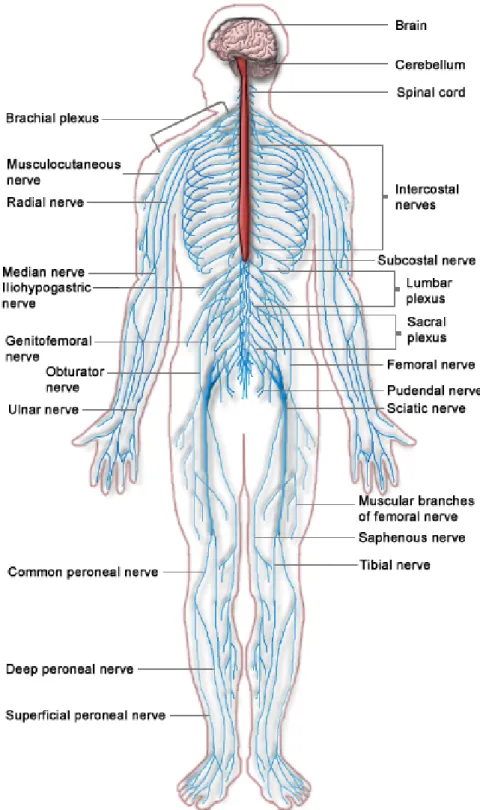
2.1 The nervous system including both the central nervous system (Red) and
the peripheral nervous system (Blue). . . 11
2.2 Sagittal view of the brain showing three main parts, cerebellum (Purple), cerebrum (Pink) and brainstem (Blue). . . 13
2.3 Cerebral cortex showing four main lobes; temporal lobe (Blue), optical lobe (Green), parietal lobe (Purple) and frontal lobe (Brown), Motor ar-eas; primary motor cortex (Grey), premotor cortex (Red), supplementary motor area (Orange) and somatosensory cortex (Pink). . . 15
2.4 The major arteries of the brain. . . 17
2.5 The Circle of Willis. . . 18
2.6 An EEG sample showing gamma waves. . . 19
2.7 Example of EMG record from the forearm using Biopac MP150 acqui-sition system, showing A) EMG amplitude against time and B) power spectral density (PSD) of EMG. . . 23
2.8 Structure of a neuron. . . 25
2.9 Illustration of the propagation of an action potential. . . 26
2.10 A: Presynaptic Neuron, B: Postsynaptic Neuron, 1: Mitochondria, 2: Neurotransmitters, 3: Receptor, 4: Synapse, 5: Postsynaptic receptors activated by neurotransmitter, 6: Calcium channel, 7: Exocytosis of a vesicle, 8: Recycling of neurotransmitter. . . 28
2.11 Illustration of: (A) healthy artery, (B) formation of a thrombus, and (C) an embolism. . . 29
2.12 The cortical homunculus map. . . 37
3.1 Example of a colour glove used for optical marker based tracking. . . 44
3.2 Example of silhouette method used for hand detection. . . 45
3.3 Photograph of the Sayre Glove. . . 47
3.4 Photograph of the VPL DataGlove. . . 49
3.5 Photograph of the Nintendo PowerGlove. . . 50
3.6 Photograph of the CyberGlove II1. . . 51
3.7 Photograph of the CyberGlove III2. . . 51
3.8 Photograph of MIT’s AcceleGlove. . . 52
3.9 Photograph of the 5DT Data Glove3. . . 53
3.10 Photograph of the Dexterous HandMaster. . . 54
3.11 Photograph of the Rutgers Master II-ND. A) Hand open, B) Hand closed. 55 3.12 Photograph of the MIT Manus . . . 64
3.13 Photograph of the MIME Robot . . . 65
3.14 Photograph of the ARM Robot . . . 67
3.15 Photograph of the Bi-Manu-Track robot . . . 68
3.16 Photograph of the RUPERT robot . . . 70
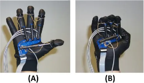
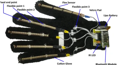
4.1 Sensor glove: highlighting main components and joints. . . 96
4.2 Sensor glove . . . 96
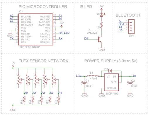
4.3 Electronic schematics for sensor glove system. . . 98
4.4 Skeleton structure of the human hand. . . 100
4.5 (a) proceeding pose, (b) attempted pose and (c) succeeding pose . . . 102
4.6 NEC transmission protocol: illustrating, leading pulse, 8-bit address, log-ical inverse of address, 8-bit command, loglog-ical inverse of command and end of transmission burst. . . 103
4.7 Illustation of NEC logic encoding . . . 103
4.8 Raw data output from sensor glove: illustrating, (a) period of rest, (b) initial movement, (c) brief maximum clenching of the hand into a fist, (d) rapid opening and closing of the hand, (e) transient muscle spasm while returning to rest. . . 104
4.9 Illustration of custom data framing protocol. . . 108
4.10 Screen capture of the Ditto software platform showing real time capture of sensor data articulating a 3D model hand. . . 110
4.11 Skeleton structure of LibHand . . . 111
4.12 BVH Format . . . 113
4.13 The LEAP Motion controller showing coordinate system. . . 119
4.14 Hand tracking using the LEAP motion controller, showing coordinate system used. . . 120
4.15 Finger tracking model using by the LEAP controller, showing vectors which provide position of a finger tip and the general direction in which a finger is pointing. . . 121
4.16 Hybrid system overview . . . 122
5.1 Proportional Position Controller. . . 130
5.2 Boxing metaphor illustration of game theoretic principles of how a players choice of action depends critically on the action of others. . . 134
5.3 Learned Dependency . . . 143
5.4 Learned Dependency . . . 144
5.5 Simulation 3 results. . . 145
6.1 Photograph of custom designed hand dynamometer, showing A) Strain gauge sensor, and B) Terminal connections. . . 154
6.2 Quarter bridge Wheatstone bridge and amplifier circuit . . . 155
6.3 Photograph of custom designed hand dynamometer and acquisition cir-cuit, showing; A) Custom hand dynamometer (V.1.), B) Wheatstone bridge amplifier and filters, C) Power regulation electronics, D) Isolated power supply, E) Status LEDs and switch, F) Output signal to digital acquisition board, and G) Load cell input connector. . . 156
6.4 System diagram of custom hand dynamometer and feedback System. . . . 157
6.5 Real time plotting of Hand Dynamometer data. . . 157
6.7 Conventional Bandwidth feedback paradigm, illustrating desired perfor-mance with a dashed green line, and with upper BU and lowerBL
band-width limits with a continuous red line. . . 158
6.8 Custom bandwidth feedback paradigm, illustrating desired performance with a dashed green line, and with upper BU and lower BL bandwidth limits for each bandwidth zone with a additional continuous coloured lines.159 6.9 Experiment 1 results - effort over time for each subject while being given direct access to performance. . . 161
6.10 Experiment 2 results - effort over time for each subject while receiving feeback from a ‘demanding’ therapist (therapist 3, table 1). . . 162
6.11 Experiment 3 results – switching after 5 seconds from a ‘demanding’ ther-apist (therther-apist 3, table 1) to a ‘unconditional’ therther-apist (therther-apist 4, table 1) who reports ‘excellent’ feedback regardless of the error. . . 162
6.12 Electronic schematic of custom hand dynamometer interface . . . 166
6.13 Simplified block diagram of the ModularEEG analogue board . . . 168
6.14 Simplified block diagram of the ModularEEG digital board . . . 169
6.15 LTspice Simulation of Besselworth filters showing, plot of filter’s response on left and filter schematics on right. . . 170
6.16 Demonstration of EMG filtering stages, including plots of; A) Hand dy-namometer recording for reference, B) Raw unfiltered EMG signal, C) De-trended EMG (removal of DC offset), D) 50Hz notch filtered EMG, and E) Bandpass filtered (10-300Hz) EMG using a Butterworth filter . . . 172
6.17 Demonstration of EMG filtering stages, including plots of; A) PSD of raw EMG, B) PSD of De-trended EMG, C) PSD of notch filtered EMG, and D) PSD of butterworth filtered EMG. . . 173
6.18 Simplified system overview diagram. . . 174
6.19 Picture of custom EMG rig, showing; A) Digital Board, B) Analogue Board encased in RF shielding, C) Electrode interface, E) Bluetooth mod-ule, F) Isolated power supply, G) Interface bridge between Analogue and Digital boards, H) Micro-controller, I) Hand Dynamometer interface. . . . 174
6.20 Electrodes attached to arm connected to EMG rig, showing; A) CMS ac-tive (+) electrode and B) CMS acac-tive (-) electrode, and C) DRL reference electrode position on bone. . . 175
6.21 Screen cast of custom physiological data visualisation software, showing; A) Plot of EMG Amplitude over time, B) Plot of load-cell output over time, C) Calculated MNF over time, D) Debug window showing status output, and E) Virtual COM port selection menu. . . 175
6.22 Results of test using Biopac DA100C amplifier illustrating, A) Power (EMG amplitude) against time and B) Power spectral density of EMG data. . . 176
6.23 Results of test using custom EMG amplifier illustrating, A) Power (EMG amplitude) against time and B) Power spectral density of EMG data . . . 176
6.24 Mechanism for delivering extrinsic feedback during training. . . 177
6.25 Illustration of feedback and grip strength mapping, showing grip strength in blue, target force in green and bands in purple with correlating textual feedback between bands. . . 178
6.26 Minimum effort (Kg) . . . 180
6.27 Mean effort (Kg) . . . 180
6.28 Sum of effort (Kg) . . . 180 xiv
6.29 Sum of absolute error (Kg) . . . 181 6.30 Mean group effort (Kg) across Sets . . . 181 6.31 Variance of group effort (Kg) across Sets . . . 181 6.32 Random sample of trials chosen from Set 3 (i.e. Bandwidth = 20%)
illustrating reduction of force over time if feedback is optimal, illustrating grip strength in blue, target force in green and bandwidth (upper and lower) dashed red line and slacking in Purple. . . 182 6.33 Reference signal showing extended grip exercise containing muscle fatigue
and the response of MNF. . . 184 7.1 Photograph of hand in pneumatic glove when fully deflated, illustrating
rest state of the hand and fingers. . . 191 7.2 Photograph of hand in pneumatic glove when fully inflated, illustrating
wrist extension and flexion of digits. . . 192 7.3 Custom pneumatic control system, showing; A) Air inlet valve, B) Air
outlet valve, C) Vacuum pump, D) Electronic control system, E) Arduino, F) USB data interface, G) Power supply, H) Intersection to air glove. . . . 192 7.4 Illustration showing configuration of pumps, (A) intake value, (B) outlet
value, arrows show the direction of airflow. . . 193 7.5 Custom electronic control system for controlling air flow to glove. . . 194 7.6 Electrode placement on the scalp according to 10-20 system, highlighting
in green the 27 active electrodes positioned over the sensori-motor area that were used to record data for experiment. . . 195 7.7 BCI system overview . . . 196 7.8 Experiment set-up showing BCI system and monitor with feedback arrow
indicating activity to perform. . . 197 7.9 LDA classifier output with event timings (top) and illustrated air pressure
in the glove (bottom) . . . 198 7.10 Abstract overview of intelligent mirror approach. . . 202 7.11 Example of face image labelled with 54 landmarks . . . 204 7.12 Image articulating landmark points: blue points illustrate strong
land-marks while red points illustrate weaker supplementary points. . . 209 7.13 Base shape showing annotation points. . . 212 7.14 Base shape showing triangulated mesh. . . 213 7.15 Image showing the misclassification of a face by an AAM after 50 steps. . 214 7.16 Initial detection and localisation of face in image using Haar cascade
clas-sifier. Red bounding box identifies location of face. . . 215 7.17 Successful detection and classification of face in 6 steps, using Haar
Cas-cade Classifier to constrain search space. . . 215 7.18 Illustration of relocating key facial points to synthesis FMS paralysis. . . 217 7.19 Image sequence showing generation of progressive HB scored facial
paral-ysis; (I) Normal, (II) Slight, (III) Moderate, (IV) Moderately severe, (V) Severe. . . 219 7.20 Image sequence showing generation of progressive HB scored facial
paral-ysis; (I) Normal, (II) Slight, (III) Moderate, (IV) Moderately severe, (V) Severe. . . 220 B.1 Analog Schematics . . . 230 B.2 Digital Schematics . . . 231
2.1 EEG frequency bands and associated functions. . . 19
4.1 Hand Gestures and resulting command codes . . . 105
4.2 Average sensor glove testing results across subjects. . . 106
5.1 Payoff table for a game of Matching Pennies . . . 135
5.2 Pay-off table for a prisoners dilemma game . . . 137
5.3 Statistical analysis of simulation results . . . 145
6.1 Agent output in response to quantitative task performance measures (nor-malised error). The values indicate breakpoints above which the associ-ated row label is produced for each therapist. For example, only a score of 0.1 or above will elicit the response “Excellent” for Therapist 1 . . . 160
6.2 Experiment 1 – Quantified Results . . . 162
6.3 Experiment 2 – Quantified Results . . . 163
6.4 Experiment 3 – Quantified Results . . . 163
6.5 Intermediate MVC recordings (Kg) . . . 183
6.6 MNF results - slope of best fit line . . . 183
7.1 Rehabilitation BCI classification accuracy results. . . 198
7.2 House-Brackmann Scoring System. . . 216
7.3 AAM fitting and image warping timings . . . 221
AAM ActiveAppearance Model
AAN Assist-as-needed
AAROM ActiveAssist Range of Motion
AT AssitiveTechnology
ABMS Agent-based Modelling and Simulation
ACA AnteriorCerebralArtery
ADC Analog toDigital Conversion
ADL Activities of DailyLiving
AMPA Alpha-Amino-3-Hydroxy-5-Methyl-4-Isoxazole Propionic Acid
ANOVA Analysis Of Variance
API ApplicationProgramInterface
AR AugmentedReality
AVM Arteriovenous Malformation
BCI Brain Computer Interface
BPS Bits PerSecond
BT Bluetooth
BVH BiovisionHierarchical
CIMT Constraint InducedMovement Therapy
CMS CommonMode Sense
CNS Central NervousSystem
CSM CorticalStimulationMapping
CSP CommonSpatialPatterns
CVA Cerebrovascular Accident
CVD CardiovascularDisease
CVI Cerebrovascular Incident
DDA Dynamic Difficulty Adjustment
DRL Driven RightLeg
ECG Electrocardiogram
EEG Electroencephalograph
EDR ElectrodermalResponse
ESD EarlySupportedDischarge
FMS Facial Motor System
FPS Frames PerSecond
fMRI Functional MagneticResonanceImaging
GSR GalvanicSkin Response
GRASP Graded Repetitive Arm Supplementary Program
HB House Brackmann
HBR Home Based Rehabilitation
HEG Hemoencephalography
IMU Inertial MeasurementUnit
IMMS Inertial Magnetic MeasurementSystem
IoT Internet of Things
IR Infrared
KP Knowledge of Performance
KR Knowledge of Results
LDA LinearDiscriminate Analysis
LED LightEmitting Diode
LIS Locked-inSyndrome
LTD Long Term Depression
LTP Long Term Potentiation
MCA MiddleCerebral Artery
MDF MedianFrequency Analysis
MEMS Micro Electrical Mechanical Systems
MNF MeanFrequency Analysis
MUAP Motor Unit Action Potential
MVC Maximum VoluntaryContraction
NMDA N-Methyl-D-asparticAcid
PROM Passive Rangeof Motion
PID Proportional IntegralDerivative
PSD Power SpectralDensity
PCA Principal Component Analysis
PWM Pulse Width Modulation
PCB Printed CircuitBoard
PET Positron Emisson Tomography
PNS Peripherial NervousSystem
PPG Photoplethysmograph
RCT RandomisedClinicalTrials
RGS RehabiliationGamingSystem xviii
SAR Socially Assistive Robotics
SMR SensorimotorRhythm
TIA TransientIschaemic Attack
UART UniversalAsynchronous Receiver/Transmitter
Matrix Notation X Two-dimensional matrix
XT Transpose ofX
xij Element at row i, columnj, of matrix X
endless opportunities, encouragement, support and most of all love
they have given me throughout my life.
Introduction
The average age of the world’s population is increasing at an unprecedented rate. A report commissioned by the U.S. National Institute on Aging estimates that the current number of people worldwide age 65 and older is 524 million. By the year 2050, that number will have reached 1.5 billion [354]. To put these figures into perspective, in just under 40 years, the proportion of older people will double from 7% to 14% of the world’s total population. While this shift in population demographics will have many unforeseeable effects on society, it will inevitably lead to a rise in the number of people living with chronic illnesses such as cardiovascular diseases (CVD), cancer, chronic obstructive pulmonary disease, dementia and diabetes.
Of such diseases, stroke a subtype of CVD is of particular concern, being the second leading cause of death above the age of 60 [396] and the leading cause of long-term disability worldwide [254]. Globally, 15 million people suffer a stroke each year, one-third die, one-one-third make a reasonable recovery and one-one-third are left with moderate to severe disability [237] with major impact on their quality of life. Given that age is one of the most substantial risk factors for stroke, with the risk of stroke doubling each decade after 55, the ageing of the world population implies a growing number of people at risk [49].
A stroke is a brain attack, characterised by the sudden interruption of blood flow to the brain causing the loss of brain function. Each stroke is unique and can effect physical, cognitive and emotional functioning. The affects of stroke are dependent on the type of stroke, the location in the brain and the extent of the resulting brain injury. The most common impairment caused by stroke is motor impairment [390], which can be regarded as a loss or limitation of function in muscle control or movement. More specifically, weakness in the upper limbs is the most common impairment after stroke
effecting approximately 80% of patients [200]. Movement impairment is categorised according to severity of deficit, e.g. from weakness in an individual limb, movement weakness on one side of the body (hemiparesis) or the inability to move one side of the body (hemiplegia). The loss of functional ability is a significant impairment for an individual, limiting their ability to engage in activities of everyday living, reducing their quality of life and their independence. Therefore, much emphasis is put on the restoration of motor function and the recovery of functional movement skills during stroke rehabilitation.
The mechanisms of recovery after stroke are complicated. In general, motor recovery depends on the plasticity of neurons and circuits within the motor system [187]. The brain has some innate capacity to recover following the stroke, known as spontaneous recovery [310], during this period improvement in physical, cognitive, and communica-tion deficits may occur on their own. However, the brain can also extensively remodel after stroke, primarily through a process called neuro-plasticity [321]. Neuro-plasticity is defined as the ability of the brain to change its structure and/or function in re-sponse to internal and external constraints and goals [150]. Fundamental research has demonstrated that reorganization is not driven simply by increased use and instead that expansion of cortical representations requires skill dependent motor learning behaviour. As a result, it is well established that rehabilitation therapy comprising task-specific, repetitive, prolonged movement training with learning can have a significant impact on recovery outcomes [112],[131]. In most cases, stroke rehabilitation begins while the patient is still in acute care and continues long after returning home. The duration of rehabilitation differs from patient to patient, some stroke survivors recover quickly, however most need some form of stroke rehabilitation long term, possibly months or years after their stroke.
Positive outcome of physical rehabilitation after neurological impairment depends heavily on the onset, duration, intensity and task-orientation of the training. Treat-ment of motor defects after stroke is subsequently labour intensive, requiring extensive, protracted one-to-one manual interactions with a physical therapist, constituting a sig-nificant burden for the therapist and decreasing the availability of rehabilitation services. Subsequently, stroke imposes a major economic burden on healthcare systems worldwide. A recent study comparing international stroke cost showed that on average, 0.27% of gross domestic product is spent on stroke by national health systems, and that post stroke care accounts for approximately 3% of total national health care expenditures [102]. These problems will most likely exacerbate in the future as life expectancy con-tinues to increase [260], resulting in an increase in the incidence of stroke, accompanied by a growing population of elderly people with moderate and severe motor disabilities. In
addition, the rising disproportion of older people will also result in there being a smaller “working age” population to care for those afflicted with disability and to contribute taxes to pay for national healthcare services.
Consequently, healthcare providers are actively investigating alternative approaches to providing healthcare services post stroke. Early supported discharge (ESD) accompa-nied by home-based rehabilitation (HBR) is one such intervention under consideration which has gained much appraisal. Studies suggest that ESD can provide a cost-effective alternative in the management of stroke care and can reduce the amount of time pa-tients spend in hospital [109],[310],[28]. Advocates of such programs suggest that in addition to economic benefits there are several additional advantages to moving towards a HBR paradigm including; reduced risks of nosocomial acquired illnesses and less dis-tress caused from prolonged hospital stay [11]. In addition, the home centred treatment paradigm gives people the advantage of practising skills and developing compensatory strategies in the context of their own home. However, to be successful, such programs will need to deliver results which are comparable to that of conventional clinical rehabil-itation. Currently, there are some distinct disadvantages to home based rehabilitation programs. First, there is a dearth of affordable specialised equipment available to sup-port home based rehabilitation programs. Second, there is evidence to suggest that adherence to rehabilitation programs is poor in the absence of supervision [26],[370]. As a result, there is both an imminent need and an opportunity to develop new technology that can supplement the efforts of healthcare specialists, through the addition of devices that can augment the benefits of therapeutic intervention and which can encourage continuous adherence with unsupervised exercise programs.
Computing technology is pervasive, each decade bringing smarter, cheaper and more powerful devices to the market place. It may be hard to believe but by today’s standards the computer NASA used to put a man on the moon is no more powerful than some pocket calculators [130]. It is estimated that there are approximately 2 billion personal computers (PCs) actively in use as of 2014, with countless more office based and au-tonomous systems in use world-wide [116]. Indeed, computers have become much more than simple tools of labour and now play an active role in how we live, socialise and even identify ourselves. The internet has created a global connectedness of unimagin-able proportion allowing us to instinctively interact with systems, purblind to the reality that such information might be stored on a machine half a world away. Technology is also advancing rapidly, capturing the imagination of a world desperate for more con-nectivity, desiring smarter, more intuitive means of interacting with their world, which is rapidly becoming more and more digital. While the driving force behind much of this technology is commercial products, this technology also represents great hope for
millions of people worldwide suffering from illness and disease. The evolving concepts of pervasive computing, ubiquitous computing and ambient intelligence are increasingly influencing health care and medicine [278, 387, 387]. Such technology has the potential to be supportive, diagnostic and analytical in an unobtrusive and even inconspicuous manner [70]. Wearable sensors and ubiquitous computing applications have tremendous capabilities, such as remote, autonomous patient monitoring and diagnosis. While not applicable to all illnesses, such technology can play a major role in assistance health-care, offering enhancements to unsupervised forms of physical therapy in the comfort of a patient’s own home. In addition, smart systems can take measurements, quan-tify and assess on-going rehabilitation efforts and automatically adjust parameters of training programs according to patient progress. From the perspective of healthcare, there is great potential to utilise such technology to improve the efficacy of home-based rehabilitation. Capabilities such as these will no doubt help advance the paradigm shift from hospital/clinical rehabilitation towards home care, and may also enhance patient self-care and independent living.
1.1
Objective
The objective of this thesis is to contribute towards improving the efficacy of home-based rehabilitation after stroke, with focus on interventions for the upper extremity. This objective is approached from two perspectives. First, through the design and development of novel, low cost devices suitable for the home setting which can help facilitate recovery, support the ongoing rehabilitation process and to improve adherence through the provision of extrinsic feedback.
Second, to investigate the interaction dynamics of supervised assisted therapy, through the application of novel modelling techniques, with the view towards designing more ef-fective controllers for human unsupervised assisted movement therapy.
1.2
Contributions
In its entirety, this thesis has produced a number of contributions which are described below.
1. A comprehensive literature review of the state of the art in technology assisted home-based rehabilitation. The review consists of a short description of the key
domains pertaining to home-based solutions for stroke rehabilitation; wearable sensors, ubiquitous computing, ambient intelligent environments, low cost robotics and brain computer interfaces.
2. Development of a novel, affordable, open source, autonomous sensor glove system for gesture based control of home environments.
3. Investigations into the potential application of Game Theory and agent based modelling as a novel approach to modelling patient/therapist interaction dynamics with a view toward developing more efficient assistance control strategies.
4. Development of a low cost, digital hand dynamometer for measuring grip strength. 5. Development of a novel feedback platform for investigating the effects of extrinsic
feedback on motor performance.
6. Modification of an open source Electroencephalograph (EEG) platform for use as an Electromyography (EMG) acquisition platform.
7. Collection and presentation of data highlighting the effects of “slacking” by the motor system during obfuscated feedback driven exercises.
8. Design and development of an affordable, brain computer interface (BCI) driven pneumatic exercise glove system for home-based neuro-rehabilitation.
9. Demonstration of machine learning techniques for automatic facial paralysis scor-ing and the synthesis of images with successive grades of facial motor paralysis, towards the development of an intelligent feedback mirror for stroke.
1.3
List of Publications
A list of the publications produced from the thesis is presented below.
1. Coffey, A. L., Ward, T. E., & Middleton, R. H. (2011). Game Theory: A Po-tential Tool for the Design and Analysis of Patient-Robot Interaction Strategies. International Journal of Ambient Computing and Intelligence, 3(3), 43–51. 2. Coffey, A. L., & Ward, T. E. (2013). A Sensor Glove System for Rehabilitation
in Instrumental Activities of Daily Living. In Communications in Computer and Information Science (Vol. 374, pp. 135–139). Las Vegas, NV, USA: International Conference, HCI International 2013,.
3. Coffey, A. L., Leamy, D. J., & Ward, T. E. (2014). A Novel BCI-Controlled Pneumatic Glove System for Home-Based Neurorehabilitation. In 36th Annual International IEEE EMBS Conference of the IEEE Engineering in Medicine and Biology (pp. 3622 – 3625). Chicago, IL: IEEE.
4. Coffey, A. L., & Ward, T. E. (2014). Slacking in the Context of Agent-based As-sessment in Virtual Rehabilitation Systems. In 36th Annual International IEEE EMBS Conference of the IEEE Engineering in Medicine and Biology (pp. 5844–5847). Chicago, IL: IEEE.
5. Coffey, A. L., & Ward, T. E. (2015). Combined Ambient and Wearable Sensors for Gesture-Based Environmental Control in the Home. In Recent Advances in Ambient Intelligence and Context-Aware Computing (1st ed., pp. 1–21). IGI Global.
6. Hurtier, J., Van Dokkum L., Dalhoumi S., Coffey A., Perrey S., Jourdan C., Dray G., Ward T., Froger J., Laffont I. (2016). A closed-loop BCI system for rehabilitation of the hemiplegic upper-limb: A performance study of the systems ability to detect intention of movement. Annals of Physical and Rehabilitation Medicine.
1.4
Outline of the Thesis
This thesis is comprised of seven subsequent chapters, the content of which is described below.
Chapter 2 provides a background to the physiological systems and functions of inter-est in this thesis, including a detailed discussion of the nervous system, (both central and peripheral), the anatomical structure of the brain, the cerebral circulatory system, as well as an in-depth discussion of the components of neural plasticity, neurons, synapses and action potentials. In addition, specific details pertaining to the underlying cause, effects and recovery mechanisms of stroke are given. Finally, details of the physiologi-cal signals that are most commonly measured for cliniphysiologi-cal purposes and which are used through this thesis are given, including Electroencephalogram (EEG), Electromyogram (EMG) and grip strength.
Chapter 3 details the current state of the art in assisted upper extremity interven-tions and the current challenges for technology assisted soluinterven-tions. The review is sepa-rated into 4 distinct areas of interest, which are prevalent throughout this thesis. (1), a literature review of sensor gloves for the capture of hand motion data (2), a literature
review of robotic devices for rehabilitation of the upper extremity, including a detailed discussion about current approaches to control systems and control strategies. (3), a literature review of extrinsic feedback, highlighting the role of extrinsic feedback on im-plicit motor learning and discussing its capacity for enhancing participant motivation and self-efficacy after stroke. And (4), a literature review of physiological sensed feed-back (i.e. biofeedfeed-back and neurofeedfeed-back) approaches to rehabilitation, discussing the potential of such systems for enhancing motor rehabilitation in chronic stroke patients with severe movement weakness.
Chapter 4 introduces the design of a novel, autonomous sensor glove system for gesture based control of personal electronic appliances (TV, radio, etc.) and describes its potential for integrating repetitive, therapeutic practise of functional hand skills into the activities of daily living.
Chapter 5 explores the development of a virtual therapist for stroke rehabilitation. The chapter begins with the exploration of the interaction dynamics between a patient and therapist during a typical assisted movement task. After which the concept of modelling these interaction dynamics using “Game Theory” is discussed. A rudimen-tary demonstration of such an implementation is demonstrated and through simulations some interesting behavioural patterns are identified and exposed (motor “slacking” and learned dependency). Finally, a discussion follows about the potential use of such an approach for modelling patient/therapist interaction dynamics towards developing more sophisticated control systems for technology assisted movement therapy.
Chapter 6 introduces the design of a novel experimental platform for investigating the effects of obfuscated feedback on motor performance during a repetitive grip and release task. Towards this goal, the design and development of two independent low-cost tools (a digital hand dynamometer and an EMG acquisition unit) for motor function assessment are described. Using the experimental platform an experiment is performed in healthy subjects investigating the use of extrinsic feedback on performance for delivering semi-automated rehabilitation therapy. Experimental results are presented which suggest the visibility of motor “slacking” as a result of error obfuscation and a discussion of the implications of theses finding for designing feedback driven therapy solutions follows.
Chapter 7 describes efforts to utilise aspects of machine learning techniques for the development of enhanced biofeedback driven rehabilitation applications. The chapter is split into two sections. The first section describes the development of a compact, in-expensive solution for home-based motor-neurorehabilitation comprising an EEG-based brain computer interface and simplified haptic feedback system based on a pneumatic glove solution. Preliminary results are presented of a pilot study conducted with health
subjects to test the system. The second section describes the application of machine vision techniques, in particular the use of active appearance models for the tracking of key facial features, automatic scoring of facial paralysis and the synthesis of subdued feedback imagery.
Chapter 8 concludes the thesis by providing a summary of the novel contributions of the work therein and discusses future directions for research arising from the work performed.
Physiological Background
2.1
Introduction
The brain is without doubt the most complex organ in the human body. To understand just how complex the brain is, consider that the brain is made up of a network of billions of interconnected nerve cells called neurons. A neuron is an electrically excitable cell that processes and transmits information through electrical and chemical signals. Neurons have a large number of extensions, in the order of thousands, called dendrites, which can reach out and form connections with other neurons. There are approximately 100 billion neurons in the human brain, of which 30 billion are situated in our cerebral cortex, the highest functioning portion of our brain. The cerebral cortex is capable of generating 1 million billion synaptic connections. If we consider the number of possible neural circuits which could be constructed we would be dealing with hyper astronomical numbers, i.e. 10 followed by at least a million zeros. In comparison, there are 1097atoms in the known universe [89].
The connection fidelity between neuron pairs is not immutable but instead is ever changing, depending on experience and stimulus from the outside world. In this way, many neurons can form together to create neural pathways and even more complicated structures such as neural circuits and networks. It is these neural structures which give rise to extremely complex functions of the brain. Stimulus from the world around us, received by our sensory organs and passed through out peripheral nervous system to our brains modulate how these networks form and grow. From leaning how to crawl, to walking upright, to swinging a tennis racket, all of these tasks rely on highly sophisticated neural circuits, developed over years, through practise and experience. These circuits not only control how our bodies respond and function, they also mould our sense of self,
defining who we are. They form our personalities, our perceptions, our thoughts, both waking and sleeping, they shape our goals and desires and even constitute our dreams. However, like all living cells, neurons require a constant steady stream of metabolic fuel (oxygen and nutrients) in order to function correctly. In fact, neurons are highly metabolically active and therefore particularly susceptible to cell death if deprived of oxygen and nutrients for even a short period of time. The blood flow to the brain must therefore be extremely well regulated in order to keep the cells alive and hence the neural circuits intact and functioning correctly, a property referred to as homoeostasis. A disruption of the blood supply to the brain, known as a stroke, can result in rapid and widespread cell death, causing significant damage to the structure of neural circuits and therefore a cease in related neural functioning.
Fortunately, the brain can heal itself after damage through reorganisation and re-structuring of damaged neural pathways, a process known collectively as neural plastic-ity. Further, it is well established that the process of recovery after brain injury can be facilitated and even enhanced through rehabilitation therapy comprising task-specific, repetitive, prolonged movement training with learning. The question of how best to facilitate and promote such neural plastic changes in the brain, through the application of affordable technology, is the key aspiration of this thesis. However, prior to discussing how modern technology may help treat stroke and improve the lives of survivors, the physiology of the brain and the mechanics of stroke must first be introduced in more de-tail. The following chapter provides the background knowledge required to understand and contextualise the problems explored in this thesis. In addition, the physiological recording technologies and techniques used to collect data throughout this thesis are also described.
2.2
The Nervous System
The nervous system is essentially the means through which we experience and interact with the world. The nervous system is made up of the brain, spinal cord and a network of fibres and nerve cells which transmits message to and from all other parts of the body, see Figure 2.11. The nervous system can be subdivided into two main parts, the central nervous system (CNS) and the peripheral nervous system (PNS).
The CNS contains the brain and spinal cord, it is the command center of the body and is where information is processed and decisions are made, see Section 2.3.
1
The PNS consists mainly of nerves (neurons) and ganglia, which are fibre bundles that connect the CNS to every other part of the body. The purpose of the PNS is to connect the CNS to the limbs and organs, essentially acting as a communication network between the brain and the rest of the body, see Section 2.4.
Figure 2.1: The nervous system including both the central nervous system (Red) and
At the cellular level, the nervous system is comprised primarily of a special type of cell, called the neuron, also refereed to as a “nerve cell”, see Section 2.5. There are many different types of neurons. Neurons differ from one another structurally, functionally and genetically, as well as in how they form connections with other cells. As well as neurons, the nervous system also contains other specialized cells called glial cells, also known simply as glia which provide structural and metabolic support. Glial cells transport nutrients to neurons, clean up brain debris, digest parts of dead neurons and also help keep neurons in place and add insulation between them.
2.3
Central Nervous System (CNS)
2.3.1 The Spinal Cord
The spinal cord is the main pathway for information between the brain and the rest of the body. The main body of the spinal cord is a long thin strand of nerve fibres which stretch from the occipital bone down to the space between the first and second lumbar vertebrae, see Figure 2.1. The cord consists primary of two types of fibres, an efferent pathway for motor neurons, which travel from the brain towards the body to control muscle movement, and an afferent pathway for sensory neurons, which carry information from the body’s sensory organs back to the brain. The cord is segmented distally into 31 sections called nerve roots which are fundamentally clusters of nerve endings which branch off the central cord into the body. The spinal cord is protected by an outer column of bone called vertebrae. Between each two vertebrae is a disk of cartilage which helps add flexibility to the spine and to absorb shocks. The spinal cord has three main functions, it carries motor neurons from the brain to the body, it carries sensory information from the sensory organs to the brain and it coordinates certain autonomous reflexes [91].
2.3.2 The Brain
The human brain is an incredibly complex structure which until recently was considered incomprehensible. Most of what we now know about the brain was only discovered in the last 50 years and is in part because of the accelerating pace of research in neurological science and the development of new functional mapping techniques. The advent of brain imaging techniques, including positron emission tomography (PET) and functional magnetic resonance imaging (fMRI) has enabled us to peak inside the brain and glance at its inner workings. Using this technology researchers can examine in a non-invasive
manner human brain functions, by study the temporal and spatial changes in the brain as a function of various stimuli.
The brain is composed of three main parts; the cerebrum, cerebellum, and brainstem, see Figure 2.22.
Figure 2.2: Sagittal view of the brain showing three main parts, cerebellum (Purple),
cerebrum (Pink) and brainstem (Blue).
2.3.2.1 Cerebellum
The cerebellum is located posterior to the upper part of the brain stem. The cerebellum is relatively small, only accounting for 10% of the brains overall mass, however it contains approximately half of the brains neurons. Functionally the cerebellum plays an assisted role in motor control, while it does not initiate movement the cerebellum assists in the coordination and planning of voluntary movements such as; posture, balance, and speech. In addition, the cerebellum also plays an important role in motor learning, most notably in learning to adjust to dynamic changes in sensorimotor relationships [162]. The cerebellum also appears to be involved in a variety of linguistic functions [81].
2.3.2.2 Brainstem
The brainstem is located in the posterior of the brain, conjoining the brain with the spinal cord. The brainstem includes the midbrain, pons, and medulla. Though relatively small, the brainstem plays the important role of interfacing the brain with the nerve
2
Source: Diagram showing some of the main areas of the brain (cropped, colors modified and re-labelled). licensed under Creative Commons Attribution-Share Alike 4.0 International
connections of the motor and sensory systems which spread out into the rest of the body. The brainstem is also responsible for autonomic, involuntary functions of the body including basic vital life functions such as, blood pressure regulation, breathing and heart rate. The brainstem is also involved with a series of complex reflective motor functions including swallowing, chewing, posture adjustment and locomotion [171].
2.3.2.3 Cerebrum
The cerebrum is the largest part of the human brain and is associated with higher brain functionality, including perception, thought, judgement, imagination and decision making. From an evolutionary perspective, the cerebrum is the newest part of the brain and is highly developed in humans compared to other species of mammals. The surface of the cerebrum is known as the cerebral cortex or simply cortex. The cortex is only a few millimetres in thickness and consists of two cortices, separated along the sagittal plane, known as the left and right hemispheres. Although thin, the cortex contains approximately 10 billion neurons and is home to the most complex functions of the human brain. The cortex has a wrinkled texture made up of ridges called gyri (singular gyrus), and grooves or fissures called Sulci (singular sulcus). Because of this configuration two-thirds of the surface of the cortex is hidden, allowing for a much larger concentration of brain matter inside the skull. Functionally, the cerebral cortex is commonly segmented into four key areas; the frontal lobe, parietal lobe, occipital lobe and temporal lobe, see Figure 2.33.
3
Figure 2.3: Cerebral cortex showing four main lobes; temporal lobe (Blue), optical
lobe (Green), parietal lobe (Purple) and frontal lobe (Brown), Motor areas; primary motor cortex (Grey), premotor cortex (Red), supplementary motor area (Orange) and
somatosensory cortex (Pink).
Thefrontal lobeis located in the anterior of the brain and is considered our intelli-gence and emotional center and home to our personality. It controls important cognitive skills such as problem solving, long term memory, language skills, judgement, impulse control, emotional expression and sexual behaviour. At the posterior of the frontal lobe, located in the dorsal precentral gyrus, lies the motor cortex, see Figure 2.3. The motor cortex is of primary interest to this thesis as it the area of the cortex responsible for planning, control, and execution of voluntary movements of the body. The motor cortex can be sub divided into three main areas; the primary motor cortex, which generates the signals that control the execution of movement. The premotor cortex, which is re-sponsible for the preparation of movement, sensory guidance of movement and spatial guidance of movement, and the supplementary motor area, which is responsible for the planning of sequences of movement and the coordination of the two sides of the body.
Theparietal lobeis located just behind the frontal lobe, above the occipital lobe in the upper mid section of the brain. The parietal lobe contains the somatosensory cortex which is essential to the processing of the body’s senses, such as touch, pressure and pain. The main functionality of the parietal lobe is the integration of sensory information from various parts of the body. The parietal lobe also plays a part in spatial and visual perception, for example in the differentiation of size, shape and color and in language processing.
The temporal lobe is located at the base section of the brain, it contains the primary auditory cortex responsible for interpreting sound and the hippocampus associ-ated with the formulation and storage of memory. The temporal lobe is responsible for processing sensory information in order to make it understandable and comprehensible, for example in the case of deciphering meaningful speech from sound and meaningful visual information from sight. The temporal lobe is also associated with the retention of language and visual memories, and association of emotion.
Theoccipital lobeis located at the rear portion of the brain, above the brainstem. The occipital contains the primary visual cortex and is the visual processing center of the brain. The occipital lobe is involved in visual-spatial processing including, the discrimination of movement and recognition of color.
Although the brain accounts for only approximately 2% of the total body weight in humans, it requires a large portion of the body’s blood supply, approximately 15-20%. Normal healthy function of the brain is highly dependent upon adequate supply of oxygen and nutrients, distributed through a network of blood vessels, see Section 2.3.3 on Cerebral circulation. Without oxygen, brain cells die quickly, in the order of minutes after an oxygen-depriving event. Therefore, any decrease in the flow of blood to the brain can be catastrophic and may result in severe damage to the brain, resulting in impairment in function of the affected area.
2.3.3 Cerebral Circulation
Cerebral circulation refers to the movement of blood through the network of blood vessels which supply the brain. Arteries supply blood from the heart to the brain, rich in oxygen, glucose and other nutrients while veins carry the depleted de-oxygenated blood back towards the heart, removing by-products such as carbon dioxide and lactic acid. The blood supply towards the brain is supplied by two major artery pairs, the left and right vertebral arteries and the left and right internal carotid arteries, see Figure 2.44. At the base of the brain, these four arteries become interconnected by the bilateral posterior communicating arteries, forming a circle referred to as the circle of Willis, see Figure 2.55. The internal carotid arteries mainly supply the brainstem and cerebrum,
while the two vertebral arteries join together forming the basilar artery which primarily supplies the posterior part of the circle of Willis.
4
Source: Arteries beneath brain.png licensed under CC BY-SA 3.0
5
Figure 2.4: The major arteries of the brain.
From this circle, additional arteries branch off including, the anterior cerebral artery (ACA), the middle cerebral artery (MCA), and the posterior cerebral artery (PCA), supplying blood to all parts of the brain. The intention of the circle of Willis is to create redundancy in the cerebral circulation system which helps to maintain blood regulation to all parts of the brain, even if one of the major arteries becomes occluded.
Figure 2.5: The Circle of Willis.
Given that regulation of blood to the brain is so important, it is of the utmost importance that the main cerebral arteries are healthy. Failure to maintain adequate blood supply to any part of the brain, typically caused by blockage or rupture of an artery, can lead to a stroke, see Section 2.6.
2.3.4 Electroencephalography (EEG)
Electroencephalography is a technique developed for recording electrical activity of the brain, the subsequent recording is referred to as an Electroencephalogram (EEG). EEG measures voltage fluctuations in the brain resulting from neural activity [76]. Neurons are constantly exchanging ions, for example while attempting to maintain resting poten-tial and while propagating action potenpoten-tials, see Section 2.5.2 on neural transmission process. While the activity of a single neuron is difficult to detect, when neurons are
active together they cause a propagation effect or wave (moving ionic current) which can easily be detected by electrodes. When the wave of ions reaches the electrodes, they push or pull the electrons on its surface, which can be detected and recorded by sensitive electronic equipment. Recording these voltages over time gives us the EEG., see Figure 2.66.
Figure 2.6: An EEG sample showing gamma waves.
EEG can be recorded in two main ways, from subdural electrodes surgically planted on the surface or within the substance of the brain, or in a non-invasive manner from surface placed electrodes which sit on the exterior of the scalp. The amplitude of the recorded EEG data depends on many factors and can therefore vary between subjects, however a typical adult human EEG signal is approximately between (10-20)mV when measured from subdural electrodes and approximately between (10-100)µV in amplitude when measured from the scalp [21].
EEG frequencies typically range from (1–100) Hz, however most of the interesting data lies in the lower frequencies, less than 20 Hz, as most of the cerebral signals observed in the scalp EEG fall within this range [29]. In clinical practise EEG data is typically described in terms of rhythmic activity and is therefore commonly sub-categorised into frequency bands known as alpha, beta, theta and delta, see Table 2.1.
Table 2.1: EEG frequency bands and associated functions.
Band Frequency (Hz) Related Activity
Delta <4 adult: slow-wave sleep
Theta 4 - 7 drowsiness, idleness
Alpha 8 - 15 relaxed, eyes closed
Beta 16 - 31 active thinking, alert or stressed
Gamma >32 perceptual functions
Mu 8 - 12 motor function activities
EEG has a wide range of applications in modern medicine, it is used to evaluate several types of brain disorders including Alzheimer’s disease, epilepsy and narcolepsy.
6
EEG is also used to quantitatively assess drug intoxication, brain trauma or the ex-tent of brain damage in comatose patients and stroke patients. More recently EEG is finding applications in advanced research including brain computer interfacing (BCI) applications, see Chapter 3 for relevant literature on BCI.
2.4
Peripheral Nervous System (PNS)
2.4.1 Motor Unit RecruitmentA motor unit consists of one motor neuron and all of the muscle fibres it stimulates. A motor neuron is a specific type of nerve cell that controls the action of a muscle, causing it to contract or relax. A motor neuron is an efferent nerve, that is, it transmits motor commands from the brain down the spinal cord and into a muscle to produce movement. The amount of force exerted by an individual muscle fibre is dependent on two control principles; rate coding and the size principle.
2.4.1.1 Rate Coding
Rate coding relates to the frequency at which the neural signals (i.e. action potentials fired by motor neurons) get sent to a muscle telling them to contract [4]. When a single impulse is fired by a motor neuron it causes the muscle to twitch slightly and then relax again. If sufficient time elapses allowing the muscle to return to rest before a second impulse is received, the muscle will simply twitch again in the same manner as before. However, if the impulse arrives before the muscle has relaxed, it results in a greater amount of force than the first. This process can be thought of as a summation of muscle contractions. Hence, when a motor neuron increases its firing rate there is a proportional increase in the amount of force that the muscle generates. Motor unit recruitment is a measure of the number of activated motor neurons in a particular muscle, and therefore is a measure of how many muscle fibres of that muscle are activated. The larger the recruitment rate the stronger the muscle contraction will be. The maximum voluntary contraction (MVC) is known as a tetanic contraction which occurs when a motor unit has been maximally stimulated by its motor neuron, see Section 2.4.1.3.
2.4.1.2 Size Principle
The size principle refers to the systematic order in which motor units are recruited. In general, motor units are recruited in order of smallest to largest. This is known as the
Henneman’s Size Principle [238]. The reasoning behind this principle is that smaller muscles are more fatigue resistant than their larger counterparts and are therefore ac-tivated when low force is required. It also permits fine control of force at all levels of output by ramping up to larger forces by recruiting more and more muscle fibres of appropriate larger size.
2.4.1.3 Maximum Voluntary Contraction (MVC)
The maximum voluntary contraction (MVC) is the upper obtainable force threshold which a muscle group can produce. This occurs when a muscle’s motor unit is stimulated at a sufficiently high frequency, disallowing the muscle to return to baseline between twitches. The measure of MVC is a standardised, objective and sensitive tool for the measurement of muscle strength and plays an important role as a metric for gauging recovery during motor function rehabilitation after stroke. An increase in a patients MVC is a good indicator that they are recovering functional movement of an impaired limb. For stoke related weakness of the upper extremity, grip strength is often assessed as an indication of weakness and recovery. MVC is also used to monitor disease progression for slowly progressive conditions, such as motor neurone disease.
2.4.2 Neuromuscular Fatigue
Fatigue is a common symptom experienced in many disorders including, chronic ob-structive pulmonary disease, multiple sclerosis, Parkinson’s disease and post stroke [82]. Fatigue is defined as, a progressive loss of the ability to generate maximum force during, or following repeated or sustained muscle contractions, or the loss of force generation during a task [78]. Neuromuscular fatigue can be classified as either “central” or “periph-eral”. Central muscle fatigue can be thought of as an overall sense of energy deprivation caused by the CNS, while peripheral muscle fatigue is related to local muscle dynamics and reflects a muscle’s specific inability to do work.
2.4.2.1 Central Fatigue
Central fatigue is caused by a decline in the neural signal driving a muscle group that results in an overall weakening in force output. Central fatigue is characterised by a reduction in voluntary effort unrelated to metabolic exhaustion or the indication of stress such as (elevated heart rate, blood lactate, low blood sugars, etc.). While the phenomenon of central fatigue is not entirely understood, it has been suggested that
the observable reduction in neural drive during exercise may be a protective mechanism of the CNS, designed to protect against organ damage or failure, as might occur if the intensity of work was allowed to continue [31]. There is also evidence that central fatigue might be triggered by a reduction of dopamine levels in the brain and an elevation of serotonin (5-HT) [32].
2.4.2.2 Peripheral Fatigue
Peripheral fatigue results from local muscle dynamics and reflects changing internal conditions of the muscle. Peripheral muscle fatigue is primarily caused by two mech-anisms, first, through anaerobic metabolism exhaustion which is an exhaustion of fuel (i.e. adenosine, triphosphate, glycogen and creatine phosphate) needed to supply the muscle in order to do work. And second, through the build up of anaerobic metabolic by-products within muscle fibres including, lactic acid and other acidic compounds which interfere with the ability of calcium to stimulate muscle contraction [182].
Peripheral muscle fatigue can be difficult to detect because compensation can be made for declining muscle fibres by increasing the innervation frequency and/or the active number of motor units. However, this activity causes a detectable change in the firing patterns of the muscle fibres, which can be detected using an Electromyography (EMG), see Section 2.4.3.
2.4.3 Electromyography (EMG)
Electromyography (EMG) is a technique for evaluating and recording the electrical ac-tivity produced by skeletal muscles. As described previously in Section 2.4.1, muscle contractions are controlled by motor units. From an electrophysiology perspective, when a motor unit fires, see Section 2.5, an impulse (called an action potential) is carried down a chain of motor neurons to the muscle it innervates. After the action potential is trans-mitted across the neuromuscular junction, an action potential is elicited in all of the innervated muscle fibres of that particular motor unit. The summation of this electrical activity is known as a motor unit action potential (MUAP). The corresponding electri-cal activity from the composition of multiple motor units makes up the signal recorded during an EMG, see Figure 2.7.