Installation Instructions
Single Package Heat Pump
These instructions are primarily intended to assist qualifi ed individuals
expe-rienced in the proper installation of heating and/or air conditioning appliances.
Some local codes require licensed installation/service personnel for this type
equipment. All installations must be in accordance with these instructions and
with all applicable national and local codes and standards.
Read these instructions thoroughly before starting the installation. Follow all
precautions and warnings contained within these instructions and on the unit.
IMPORTANT
TMIt is the sole responsibility of the homeowner to make certain that heat pump has been correctly set up and adjusted to operate properly. The Manufacturer warrants the heat pump to be free from defects in material or workmanship for a period of one year. We will not be responsible for any costs found necessary to correct problems due to improper setup, improper installation, adjustments, improper operating procedure on the part of the user, etc.
Some specifi c examples of service calls which are not included in the limited warranty are: 1. Correcting wiring problems in the electrical
circuit supplying the heat pump.
SECTION 1. OWNER INFORMATION
WINTER HEATING
1. Outdoor air enters the heat pump.
2. The cold, heat-transfer section (outdoor coil) extracts the heat from the air as the refrigerant evaporates from a liquid to a cold gas. 3. The refrigerant, compressed to a hot gas by
the heat pump, carries the heat to the heat-transfer section (indoor coil).
4. The hot, heat-transfer section (indoor coil) releases the heat as the refrigerant condenses from a gas to a liquid.
5. The blower circulates the heat throughout the home via the supply duct.
6. The refrigerant returns to the outdoor coil and evaporates once again to absorb more heat.
SUMMER COOLING
1. Indoor air enters the return air duct.
2. The cold, heat-transfer section (indoor coil) extracts the heat from the air as the refrigerant evaporates from a liquid to a cold gas. 3. The refrigerant, drawn to the heat pump and
compressed to a hot gas, carries the heat outdoors.
4. The hot, heat-transfer section (outdoor coil) releases the heat as the refrigerant condenses from a gas to a liquid.
5. The heat pump (outdoor fan) discharges the heat to the outside air.
6. The refrigerant returns to the indoor coil and evaporates once again to absorb more heat.
5
4
1
2
3
6
2
1
5
3
6
4
2. Resetting circuit breakers or other switches. 3. Adjusting or calibrating of thermostat. To avoid misunderstandings at a later date, carefully review these responsibilities with your dealer or service company.
The heat pump system will heat and cool your home and save your energy dollars.
During the summer, a heat pump cools a house by absorbing heat from within the house and exhausting it outdoors. During the winter, a heat pump heats a house by absorbing heat outdoors and exhausting it indoors. This is an effi cient heating means because you pay for “moving” heat from outdoors to indoors, but do not pay to generate the heat.
OPERATING INSTRUCTIONS
To Operate Your Heat Pump For Cooling —
1. Set the thermostat system switch to COOL and the thermostat fan switch to AUTO. See Figure 1.
2. Set the thermostat temperature selector to the desired cooling temperature. The outdoor unit fan, the indoor blower, and the compressor will all cycle on and off to maintain the indoor temperature at the desired cooling level. NOTE: If the thermostat temperature level is re-adjusted, or if the thermostat system switch is re-positioned, the outdoor unit fan and the compressor may not start immediately. A protective timer circuit holds the compressor and the outdoor fan off for approximately six minutes following a previous operation or the interruption of the main electric power
To Operate Your Heat Pump For Heating —
1. Set the thermostat system switch for HEAT and the thermostat fan switch to AUTO. See Figure 1.
2. Set the thermostat temperature selector to the desired heating temperature. The outdoor unit fan, the indoor blower, and the compressor will all cycle on and off to maintain the indoor temperature at the desired heating level. NOTE: If the thermostat temperature level is re-adjusted, or if the thermostat system switch is re-positioned, the outdoor unit fan and the compressor may not start immediately. A protective timer circuit holds the compressor and the outdoor fan off for approximately six minutes following a previous operation or the interruption of the main electrical power.
Emergency Heat — Some thermostats will include a system switch position termed EM HT or AUX HT, etc. This is a back-up heating mode to be used only if there is a suspected problem. With the system switch set to EM HT, etc., the compressor and outdoor fan will be locked off and supplemental heat (electric resistance heating) will be used as a source of heat. Sustained use of electric resistance heat in place of the heat pump will result in an increase in electric utility costs.
Defrost — During cold weather heating operation, the outdoor unit will develop a coating of snow and ice on the heat transfer coil. This is normal and the unit will periodically defrost itself. During the defrost cycle, the outdoor fan will stop, while the compressor continues to run and heat the outdoor coil, causing the snow and ice to melt. During defrost, there may be some steam rise from the outdoor unit as the warm coil causes some melted frost to evaporate.
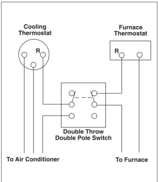
Figure 2. Thermostat Interlock System Cooling
Thermostat ThermostatFurnace
Double Throw Double Pole Switch
To Air Conditioner To Furnace
R R
Figure 1. Typical Thermostat
FAN SWITCH
SPECIFICATIONS
Single Package Heat Pumps are designed for outdoor rooftop or ground level slab installations. The units are shipped ready for horizontal duct connections and are easily converted for down fl ow applications.
All Q4RD models are shipped from the factory with the following:
1. Zero clearance to combustibles 2. Multi-speed direct-drive blower.
3. Compressor Anti-short-cycle timer for single phase models.
4. Blower Speed Relay.
5. Horizontal or Down fl ow duct connections. 6. Square-to-round adapter boxes with 14”
collars for supply and return openings. The unit dimensions are shown in Figure 3.
WARNING:
The square-to-round adapter boxes
and 14” collars are shipped inside the
return inlet. These must be removed
before the unit is run.
Optional fi eld-installed electric heater kits are available in 5 kw through 20 kw heating capacities. A separate installation instruction document for the electric heaters and their application accompanies this one. A two stage heat 24VAC thermostat should be used with electric heater kits installed.
SAFETY CONSIDERATIONS
It is the responsibility of the installer to ensure that the installation is made in accordance with all applicable local and national codes.
WARNING:
I m p ro p e r i n s t a l l a t i o n , s e r v i c e ,
adjustment, or maintenance may cause
explosion, fi re, electrical shock or other
hazardous conditions which may result
in personal injury or property damage.
Unless otherwise noted in these
instructions, only factory authorized
kits or accessories may be used with
this product. Noncompliance may void
the unit’s warranty.
Labels, Tags — When working with this equipment, follow all precautions in the literature, on tags, and on labels provided with the unit and/or approved fi eld installed kits. The type of hazard and severity are described on each label or tag.
Pressures Within The System — This equipment contains liquid and gaseous refrigerant under high pressure. Installation or servicing should only be performed by qualifi ed trained personnel thoroughly familiar with this type equipment.
INSTALLATION REQUIREMENTS
Equipment Check — Before beginning the installation, verify that the unit model is correct for the job. The unit model number is printed on the data label. All units have been securely packaged at the point of shipment. After unpacking the unit, carefully inspect it for apparent and concealed damage. Claims for damage should be fi led with the carrier by the consignee.
Requirements and Codes — The installer must comply with all local codes and regulations which govern this type equipment. Local codes and regulations take precedence over any recommendations contained in these instructions. All electrical wiring must be made in accordance with local codes and regulations and with the National Electric Code (ANSI/NFPA 70) or in Canada the Canadian Electric Code Part 1 CSA C.22.1. Air Ducts must be installed in accordance with the standards of the National Fire Protection Association “Standards for Installation of Air Conditioning and Ventilation Systems” (NFPA 90A), “Standard for Installation of Residence Type Warm Air Heating and Air Conditioning Systems” (NFPA 90B), these instructions and all applicable local codes.
NFPA publications are available by writing: National Fire Protection Association Batterymarch Park
Quincy, Maine 02269
IMPORTANT: Do Not Place Unit Under The Home.
Unit Location — This heat pump is designed only for outdoor installations. Choosing the location of the unit should be based on minimizing the length
Top View
Side View
Back View
24.9 13.5 16.0 12.0 13.3 13.5 16.0 12.0 CG A 47.5 3/4" NPT Female Drain Connector B DOWNFLOW SUPPLY DUCT OPENING DOWNFLOW RETURN DUCT OPENING 23.5 1.25 Ø Power Entry 1.75 Ø Power Entry (Capped)
0.88 Ø Control Wiring Entry
23.6 27.2 30 1.8 4.00 13.5 16.0 14.7 13.5 16.0 13.45 11.75 22.75 55.8 C SUPPLY RETURN 4.0 CONDENSING COIL 5.0 8 Figure 3. Dimensions Model Number Q4RD Unit Weight
Center of Gravity Height (in inches)
A B
C
with base rails without base rails
Condensate Drain
Figure 5. Condensate Drain
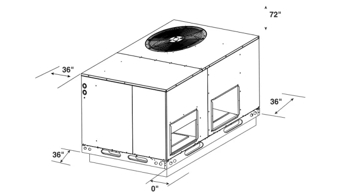
Figure 4. Minimum Clearances
located on the front side of the unit. See Figure 5. Install a 2 inch condensate trap in the drain line of the same size and prime with water. When connecting rigid drain line, hold the female fi tting with a wrench to prevent twisting. Do not over tighten! Refer to local codes and restrictions for proper condensate disposal requirements.
UNIT INSTALLATION
Ground Level — When installing the unit at ground level, provide a concrete mounting pad separate from the building foundation. The pad must be level to insure proper condensate disposal and strong enough to support the unit’s weight. Refer to Figure 3. Make sure the slab is a minimum of 2” above the grade and in an area that drains well. See Figure 6.
AIR DUCTS
This unit is designed only for use with a supply and return duct. Air ducts should be installed in accordance with the standards of the National Fire Protection Association “Standard for Installation of Air Conditioning Systems” (NFPA 90A), “Standard for Installation of Residence Type Warm Air Heating and Air Conditioning Systems” (NFPA 90B), and all applicable local codes. of the supply and return ducts. Consideration
should also be given to availability of electric power, service access, noise, and shade. Suf-fi cient clearance for unobstructed airfl ow through the outdoor coil must be maintained in order to achieve rated performance See Figure 4 for minimum clearances to obstructions.
Air Filters — A suitable air fi lter must be installed in the return air system. Air fi lter pressure drop must not exceed 0.08 inches w.c. at 300 fpm.
Condensate Drain — Condensate is removed from the unit through the 3/4” female pipe fi tting
36"
36"
0"
36" 72"
Design the duct work according to methods described by the National Warm Air Heating and Air Conditioning Association (ACCA). The ducts must be properly sized not to exceed .2” w.c. pressure drop at 400 scfm per nominal ton of cooling capacity.
Duct work should be attached directly to the unit fl anges for horizontal applications.
Installation of Square-to-Round Adapters — The square-to-round adapter panel and 14” round collars must be removed from the return inlet opening.
1) Remove the close-off plates from the supply and return openings.
2) Fit the 14” collar inside the adapter plate and secure.
3) Place the square-to-round adapter plate, one over each opening, and attach with sheet metal screws.
4) Seal around the adapter box and collars.
Refer to Figure 7 for installation.
Unconditioned Spaces — All duct work passing through unconditioned space must be properly insulated to minimize duct losses and prevent condensation. Use insulation with an outer vapor barrier. Refer to local codes for insulation material requirements.
Acoustical Duct Work — Certain installations may require the use of acoustical lining inside the supply duct work. Acoustical insulation must be in accordance with the current revision of the Sheet Metal and Air Conditioning Contractors National Association (SMACNA) application standard for duct liners. Duct lining must be UL
classifi ed batts or blankets with a fi re hazard classifi cation of FHC-25/50 or less. Fiber duct work may be used in place of internal duct liners if the fi ber duct work is in accordance with the current revision of the SMACNA construction standard on fi brous glass ducts. Fibrous duct work and internal acoustical lining must be NFPA Class 1 air ducts when tested per UL Standard 181 for Class 1 ducts.
Horizontal to Down fl ow Conversion — The unit is shipped ready for horizontal duct connections. If down fl ow ducts are required, the unit must be converted following the steps below for both the supply and return ducts.
1) Locate the duct cap inside the duct openings and remove the screw holding it in place. 2) Lift the cap out of the unit. (The cap can
be pushed up from the bottom by reaching through the fork slot).
3) Cover the horizontal duct opening with the cap. The insulation will be on the indoor side.
4) Fasten the cover with screws and seal to prevent air leakage.
Clearance — These units are approved for 0 inch clearance.
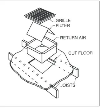
Locating and Installing the Return
Air Assembly
To avoid complications, locate and install the return air assembly fi rst. The return air box with grille and fi lter (Figure 8) should not be located in heavy traffi c areas like hallways or center of rooms. A good spot is in a corner or under a table,
2"
if a minimum two inch clearance is available. If desired, the return opening can be located inside a closet with louvered doors that have an open area equal to or greater than the return grille. The return air grille can be placed in the wall of a closet and the air ducted into the fi lter box through a boxed-in area at the closet fl oor level. Make sure the fi lter is readily accessible. After determining the location of the return air opening, start the installation from under the home by cutting a small hole in the fi ber underboard to determine how the fl oor joist location will affect cutting the opening needed for the box. Floor joists generally are located on 16” centers, leav-ing 14-3/8” between joists. After measurleav-ing the return air box, cut the hole through the fl oor so that the box will fi t between the fl oor joists. Care should be taken when cutting through carpeting to avoid snags. In most installations it will be necessary to cut a similar hole in the fi berboard directly under the hole in the fl oor. However, if the fl oor is more than ten inches deep, it will only be necessary to cut a hole for the collar on the return air box or for the insulated duct.
Set the box into the opening and fasten with screws or nails. Put the fi lter and return air grille in place.
Note: For highly resistive duct systems it may be necessary to add an additional return air duct to achieve maximum performance.
Locating and Installing the Supply
Damper(s)
When locating the supply damper(s), carefully check fl oor joists and frame members that could interfere with the installation of the damper or fl exible duct. Ideally, the damper should be located in the bottom of the main duct, forward of center of the home, at least three feet from the nearest register. The round supply opening in the slanted side of the damper should face the side of the home where the heat pump is located. To locate the center of the heat duct, fi rst cut a small hole in the fi berboard below the duct at the desired location. After locating the duct center, cut a hole approximately 3/4” larger than the damper opening in the fi berboard. Cut a 9-1/8” x 13-1/8” hole in the duct and bend over all tabs fl at on the inside of the heat duct. After inserting the damper into the duct, bend over all tabs fl at on the inside of the heat duct. Seal the opening between the fi berboard and damper or fl exible duct.
DUCTING SYSTEM
Duct Requirements
The supply duct system, including the number and type of registers, will have much more ef-fect on the performance the system than any other factor. The duct must be suffi ciently large to conduct an adequate amount of air to each register.
THE HEAT PUMP SYSTEM WILL NOT COOL OR HEAT THE HOME IF THE AIR IS LOST TO THE OUTSIDE THROUGH LEAKS IN THE DUCT SYSTEM. ALSO, DUCTS WHICH ARE COLLAPSED OR RESTRICTED BY FOREIGN OBJECTS WILL PREVENT ADEQUATE AIR FLOW.
Figure 9. Supply Damper
AUTOMATIC DAMPER IS CLOSED WHEN HEAT PUMP IS OFF
Connecting the Return and Supply
Air Flexible Ducts
a. The return and supply duct openings for all units is 14” in diameter.
b. The fl exible ducts can be connected to the corresponding fi ttings with the clamps provided with the ducts. Note: All connections should be leak tight or a loss in cooling capacity will result.
c. The fl exible ducts may be cut to the required length, see instructions packed with duct. Keep all ducts as short and straight as possible. Avoid sharp bends.
d. Ducts may be spliced with sheet metal sleeves and clamps. (See Ducting Installation Accessories below.)
e. Once the inner duct is connected to the proper fi tting, the insulation and plastic sleeve should be pulled over the connection and clamped.
f. For homes with multiple supply ducts or for special applications, a Y fi tting is available to divide the supply air so it can be ducted to different areas of the home for more effi cient cooling. Note: The Y fi tting should be insulated for maximum performance.
ELECTRICAL WIRING
General — Electrical power wiring must be made in accordance with all applicable local codes and ordinances, and with the current revision of the National Electric Code NFPA 70 or in Canada CSA C.22.1 - Canadian Electrical Code Part 1.
5 5 4 4 5 2 3 1 5 2 3 5 4 1 7
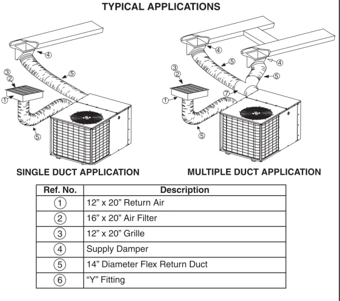
Figure 10. Typical Applications
Ref. No.
Description
1
12” x 20” Return Air
2
16” x 20” Air Filter
3
12” x 20” Grille
4
Supply Damper
5
14” Diameter Flex Return Duct
6
“Y” Fitting
TYPICAL APPLICATIONS
MULTIPLE DUCT APPLICATION
SINGLE DUCT APPLICATION
If any of the original wire as supplied with the unit must be replaced, it must be replaced with material of the same gage and temperature rating.
WARNING:
To avoid the risk of electrical shock,
personal injury, or death, disconnect
all electrical power to the unit before
performing any maintenance or
service. The unit may have more than
one electrical power supply.
Line Voltage — Before proceeding with the electrical connections, make certain that the voltage, frequency, and phase of the supply source are the same as those specifi ed on the unit rating plate. Also verify that the service provided by the utility is suffi cient to handle the additional load imposed by this equipment.
See the unit wiring label for proper high and low voltage wiring. Make all electrical connections in accordance with all applicable codes and ordinances.
Use a separate branch electrical circuit for this unit. A means of electrical disconnect must be located within sight of and readily accessibility to the unit. Internally mounted circuit breakers are available as fi eld installed options. These circuit breakers can be used as an electrical disconnect.
The unit is shipped from the factory wired for 240 volt transformer operation. For 208 volt operation, remove the lead from the transformer terminal marked 240V and connect it to the terminal marked 208V. For maximum ampacity and over current protection, see the unit rating plate. Provide power supply (or supplies) for the unit in accordance with the unit wiring diagram, and the unit rating plate. Connect the line-voltage leads to the corresponding terminals on the contactor (or the circuit breaker when the fi eld installed circuit breaker kits are used) inside the control compartment. Use only copper wire for the line voltage power supply to this unit. Use proper code agency listed conduit and a conduit connector for connecting the supply wires to the unit and for obtaining proper grounding. Grounding may also be accomplished by using the grounding lug provided in the control box.
WARNING:
The unit cabinet must have and
uninterrupted or unbroken electrical
ground to minimize personal injury if
an electrical fault should occur. This
ground may consist of electrical wire
or approved conduit when installed in
accordance with existing national or
local codes.
Blower Speed — For optimum system
performance and comfort, it may be necessary to change the factory set speed. To change the blower speed:
1. Disconnect all electrical power to the unit and remove the blower panel.
2. Locate the orange and red wires terminated to the blower motor. The orange wire controls cooling operation while the red wire controls heating operation.
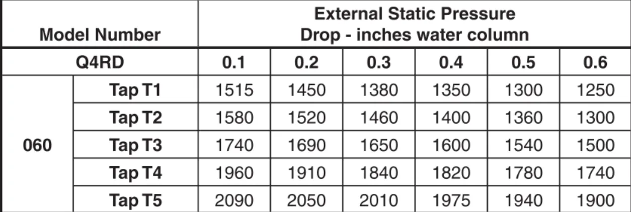
3. Verify the required speed from the airfl ow data found in table 3. Place appropriate wire on the appropriate motor speed tap for the required airfl ow point.
NOTE: If the same speed is required for both heating and cooling. Obtain the jumper wire from the homeowners packet and connect it to the blower relays at the NO & NC terminals. Be sure to only connect the speed necessary to one side of the jumper wire.
CAUTION:
To avoid personal injury or property
damage, make certain that the motor
leads cannot come into contact with
any uninsulated metal components
of the unit.
Check all factory wiring per the unit wiring diagram and inspect the factory wiring connec-tions to be sure none loosened during shipping or installation.
Low Voltage Connections
Room Thermostat — Several options are available for a room thermostat depending on
the accessories installed with the unit. Select a thermostat which operates in conjunction with the installed accessories. The thermostat should be mounted about fi ve feet above the ground on an inside wall. The thermostat should be kept away from drafts, slamming doors, lamps, direct sunlight, or in line with the supply air fl ow. To install the thermostat:
1. Position the sub base on an inside wall and mark the mounting holes and thermostat cable openings.
2. Cut out the cable opening and route the thermostat cable from the unit’s low voltage compartment to the thermostat location. The thermostat cable is supplied by the installer.
3. Connect the cable leads to the sub base or thermostat terminals and to the unit’s low voltage pigtails as shown in Figure 10. A system wiring diagram is also provided on the inside of the control panel cover. 4. Secure sub base or thermostat to the
wall using screws provided with the thermostat.
5. If sub base is used, install the correct thermostat housing to sub base.
6. Refer to thermostat instruction sheet for complete detailed mounting information.
Defrost Cycle Timer — The defrost cycle timer controls the time interval of the hot gas defrost after the defrost sensor closes. It is located in the lower left corner of the defrost control board on the low voltage side of the control box. Three interval settings are available: 30 minutes, 60 minutes, and 90 minutes. Time setting selection is dependent on the climate where the unit is being installed.
Example 1. Dry climate of Southern Arizona. A 90 minute setting is recommended.
Example 2. Moist climate of Seattle, Washington. A 30 minute setting is recommended.
To set the cycle timer, place the timing pin on the defrost control board to the desired time interval post.
Note: All units are shipped from the factory with the default time setting of 30 minutes.
Field Installed Electric Heat — These Single Package Heat Pumps are designed to allow optional electric heat to be fi eld installed as required by the building’s particular heating load. The options available for each unit are shown in the heater kit installation instructions. As noted in the instructions, a fi eld installed circuit breaker kit is available as a means of electrical discon-nect for the unit.
Install the heater kits as directed by the installation instructions that come as part of the heater kit. Follow all cautions and warnings as directed.
START UP AND SYSTEM CHECK
Pre-Start Check List
• Verify that the unit is level to allow proper condensate drainage.
• Verify that there is free airfl ow to and from the outdoor coil and that all clearance requirements are met.
• Verify that the duct work is sealed to prevent air leakage.
• Verify that the line voltage power leads are securely connected and the unit is properly grounded.
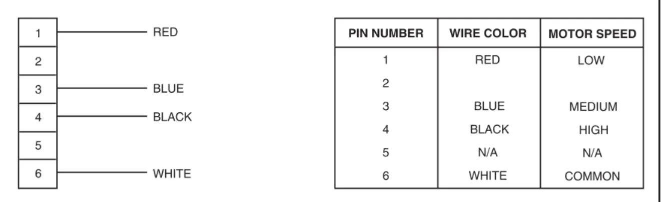
Figure 11. Motor Lead Connector
PIN NUMBER WIRE COLOR MOTOR SPEED
1 RED LOW 2 4 BLACK HIGH 3 BLUE MEDIUM 5 N/A N/A 6 WHITE COMMON 1 2 4 3 5 6 RED BLACK BLUE WHITE
• Verify that the low voltage wires are securely connected to the correct leads on the low voltage terminal strip.
• Verify that all exterior panels are replaced and securely fastened.
• Verify that the outdoor fan turns freely. • Verify that the power supply branch circuit
overcurrent protection is sized properly. • Verify that the thermostat is wired correctly.
The thermostat function switch should be set to “Off’ and the thermostat fan switch should be set to “Auto.”
Start-Up Procedure
Close all electrical disconnects to energize the system.
WARNING:
If the unit is equipped with a crankcase
heater, allow 24 hours prior to
continuing the start up procedures
to allow for heating of the refrigerant
compressor crankcase. Failure to
comply may result in damage and
could cause premature failure of
the system. This warning should be
followed at initial start up and any
time the power has been removed for
12 hours or longer.
Air Circulation — Leave the thermostat system switch set to “Off” and set the thermostat fan switch to “On.” The blower motor should run continuously. Check for air delivery at the register(s). Ensure that there are no obstructions at the registers or in the duct work. Set thermostat fan switch to “Auto.”
Short Cycle Protection — With the system operating in cooling mode, note the temperature setting of the thermostat and gradually raise the set-point temperature until the unit de-energizes. Immediately lower the set point temperature of the thermostat to its original setting and verify that the indoor blower is energized. Verify that after approximately 5 minutes the compressor and fan energize and that the temperature
of the discharge air is cooler than the room temperature. This is available only for the single phase models.
System Cooling
1. Set the thermostat system switch to “Cool” and the thermostat fan switch to “Auto”. Gradually lower the thermostat temperature switch below room temperature and observe that the blower, compressor, and fan energize. Check that air cooler than room temperature is being discharged at the register. Listen for any unusual noises.
2. After allowing the unit to run for several minutes, set the temperature selector above room temperature.
- The fan and compressor cycles off with the thermostat.
- The blower should also stop unless fan switch is set to “ON” position.
System Heating — If the unit has been equipped with optional electric heater kits, set the system thermostat switch to HEAT and set the thermostat fan switch to AUTO. Verify that the compressor and outdoor fan are not energized but that the blower and heaters are. Check for warm air at the supply registers.
UNIT MAINTENANCE
WARNING:
To avoid risk of electrical shock,
personal injury, or death, disconnect
all electrical power to the unit before
performing any maintenance or
service. The unit may have more than
one electrical supply.
Refrigerant Charging — Packaged heat pumps are fully charged at the factory . The system refrigerant charge can be checked and adjusted through the service ports provided in the front panel. Use only gauge lines which have a “Schrader” depression device present to actuate the valve. Draw a vacuum on gauge lines to remove air before attaching them to the service ports on the unit. Refrigerant charging must be done by qualifi ed personnel familiar with safe and environmentally responsible refrigerant handling procedures.
WARNING:
Single Packaged Heat Pumps are
shipped fully charged and ready for
installation. When a system is installed
according to these instructions, no
refrigerant charging is required.
If repairs make it necessary for
evacuation and charging, it should
only be done by qualifi ed, trained
personnel thoroughly familiar with this
equipment. Some local codes require
licensed installation/service personnel
to service this type of equipment.
Under no circumstances should the
owner attempt to install and/or service
this equipment. Failure to comply with
this warning could result in property
damage, personal injury, or death.
CAUTION:
Use care when removing parts from
this unit. Personal injury can result
from sharp metal edges present
in all equipment of sheet metal
construction.
Routine Maintenance — Proper maintenance is important to achieve optimum performance from
the heat pump. The ability to properly perform maintenance on this equipment requires certain mechanical skills and tools. If you do not possess these skills, contact your dealer for maintenance. Consult your local dealer about the availability of maintenance contracts. At a minimum, routine maintenance should include the following:
1. Inspect and clean or replace air fi lters at the beginning of each heating and cooling season, or more frequently if required. 2. Inspect the condensate drain and outdoor
coil at the beginning of each cooling season. Remove any debris. Clean the outdoor coil and louvers as necessary using a mild detergent and water. Rinse thoroughly with water.
3. Inspect the electrical connections for tightness at the beginning of each heating and cooling season. Service as necessary.
CAUTION:
The unit should never be operated
without a fi lter in the return air system.
Replace disposable fi lters with the
same type and size.
4. The motors for the circulating air blower and the outdoor fan are pre-lubricated at the factory. No further oiling is required for the life of this product.
Table 1. Blower Curves
* Denotes factory set cooling and heat pump speed ** Denotes factory set electric heating speed
Model Number
External Static Pressure
Drop - inches water column
Q4RD
0.1
0.2
0.3
0.4
0.5
0.6
060
Tap T1
1515
1450
1380
1350
1300
1250
Tap T2
1580
1520
1460
1400
1360
1300
Tap T3
1740
1690
1650
1600
1540
1500
Tap T4
1960
1910
1840
1820
1780
1740
Tap T5
2090
2050
2010
1975
1940
1900
E O G R Y1 1 2 3 4 5 6 7 8 9 Blue ECONOMIZER PLUG INDOOR THERMOSTAT SUB-BASE Green FROM BLOWER RELAY Y2 W2 C DEFROST BOARD 1 2 3 4 5 6 7 8 9 Brown Orange Accessory Heat Plug
Typical Wiring (Field Supplied) for 1-Stage Cool, 1 Stage Electric Heat
Typical Wiring (Field Supplied) for 2-Stage Cool, 2-Stage Electric Heat with an Optional Outdoor Thermostat
E O G R Y1 1 2 3 4 5 6 7 8 9 Blue ECONOMIZER PLUG INDOOR THERMOSTAT SUB-BASE Green FROM BLOWER RELAY Y2 W2 C DEFROST BOARD 1 2 3 4 5 6 7 8 9 Brown Orange Accessory Heat Plug Optional Outdoor Thermostat (Field Supplied) O
5 OUTDOOR TEMPERATURE (°F) TON 70 75 80 85 90 95 100 105 Suct. Press. Dis. Press. Dis. Temp. Dis. Press. Dis. Temp. Dis. Press. Dis. Temp. Dis. Press. Dis. Temp. Dis. Press. Dis. Temp. Dis. Press. Dis. Temp. Dis. Press. Dis. Temp. Dis. Press. Dis. Temp. 67 154 140 69 156 146 173 146 71 158 151 176 152 193 152 73 160 158 178 157 195 157 212 158 75 163 160 180 162 197 162 214 163 231 164 77 183 165 199 167 216 168 233 168 251 170 79 203 170 219 172 235 173 253 174 270 175 81 222 175 238 177 255 178 272 179 289 180 83 226 179 242 181 258 182 274 183 291 184 85 245 185 261 186 278 187 293 188 87 265 190 281 192 297 193 89 284 196 301 197 91 304 202 93
Table 2. 13 SEER Cooling Charging Charts
Cooling Charging Chart
* Note: All pressures are listed in psig. and all temperatures in deg. F. — Shaded Boxes indicate fl ooded conditions
— Rated Design Values. Suction Pressure will be lower than design value if indoor airfl ow, entering dry bulb, or entering wet bulb tem-peratures are lower than design.
— Discharge temperatures greater than charted values indicates a refrigerant undercharge.
¢7105753
¤
1. Disconnect all po wer bef o re ser vicing. 2. For supply connections use copper conductors on
ly
.
3.
Not suitable on systems that e
xceed 150
V to gr
ound.
4.
If an
y of the original wire as supplied with the furnace m
ust be replaced,
it m
ust
be replaced with wiring material ha
ving a temperature rating of at least 105°C.
5.
For suppl
y wire ampacities and o
ver
current pr
otection,
see unit rating plate
.
1.
Couper le courant a
v
ant de faire letretien.
2.
Emplo
yez uniquement des conducteu
rs en cuivre
.
3.
Ne con
vient pas aux installations de plus de 150
V a la terre . 7105750 N NO TES:
DEFROST BOARD OPERATION: CLOSES DURING DEFROST. RAITNG: 1 A MAXIMUM OPENS DURING DEFROST. RATING: 2 HP AT 230 VAC MAXIMUM CLOSED WHEN “Y” IS ENERGIZED. OPEN WHEN “Y” IS DEENERGIZED. PROVIDES “OFF” DELAY TIME OF 5 MIN WHEN “Y” IS DEENERGIZED. WITH DFT CLOSED AND “Y” ENERGIZED, COMPRESSOR RUN TIME IS ACCUMULATED. OPENING OF DFT DURING DEFROST OR INTERVAL PERIOD RESETS THE INTERVAL TO 0. 1 2 3 4 C R S C HF E DFT R W2 0 Y C T 2 T 1 DF2 DF1 C Y 0 W2 R E PRESSURE SWITCH (IF EQ UIPPED) T O 208/230 V A C PO WER SUPPL Y BLO W ER MO T O R T1 T3 T4 T2 G N L C 2 3 4 5 6 7 8 9 1 2 3 4 5 6 7 8 9 1 2 3 4 5 6 7 8 9 1 2 3 4 5 6 7 8 9 1 8 7 6 5 4 3 2 1 9 8 7 6 5 4 3 2 1 9 T5 DEFR OST SENSOR COMPRESSOR CONT A C T O R OUTDOOR F A N MO T O R COMPRESSOR DU AL CAP A CIT O R HEA TER PLUG REVERSING VA L V E SOLENID 3 AMP FUSE DEFR O ST CONTR OL BO ARD T O INDOOR THERMOST A T T O DISCHARGE AIR SENSOR BLO W ER RELA Y TRANSFORMER C R S L2 L1 T1 T2 13 56 24 24V COM 208V 240V
ECONOMIZER JUMPER HARNESS ASSY
9-WIRE GB ECONOMIZER PLUG ECONOMIZER PLUG BR O W N WHITE BLA C K RED BLUE YELLO W YELLO W
RED RED BLUE
BLA C K GREEN ORANGE GREEN GREY GREEN WHITE WHITE WHITE BLA CK BLUE BLA C K BLA CK BLA C K BLA CK BLA C K ORANGE WHITE WHITE RED RED RED BR O W N YELLO W YELLO W GREY GREEN BLUE BLA C K YELLO W ORANGE ORANGE GREEN/YELLO W BLUE BR O W N RED RED RED RED RED Leg end Field Wiring F a ctor y Wiring: Lo w V o lta g e High V olta g e
Note: See Installation Instructions for wiring, application, and information concerning accessory Heat Kits and other options.
ORANGE
WD #7105830
¢710583,
¤
1. Disconnect all po wer bef o re ser vicing. 2. For supply connections use copper conductors on
ly
.
3.
Not suitable on systems that e
xceed 150
V to gr
ound.
4.
If an
y of the original wire as supplied with the furnace m
ust be replaced,
it m
ust
be replaced with wiring material ha
ving a temperature rating of at least 105°C.
5.
For suppl
y wire ampacities and o
ver
current pr
otection,
see unit rating plate
.
1.
Couper le courant a
v
ant de faire letretien.
2.
Emplo
yez uniquement des conducteu
rs en cuivre
.
3.
Ne con
vient pas aux installations de plus de 150
V a la terre . 7105830 NO TES:
DEFROST BOARD OPERATION: CLOSES DURING DEFROST. RAITNG: 1 A MAXIMUM OPENS DURING DEFROST. RATING: 2 HP AT 230 VAC MAXIMUM CLOSED WHEN “Y” IS ENERGIZED. OPEN WHEN “Y” IS DEENERGIZED. PROVIDES “OFF” DELAY TIME OF 5 MIN WHEN “Y” IS DEENERGIZED. WITH DFT CLOSED AND “Y” ENERGIZED, COMPRESSOR RUN TIME IS ACCUMULATED. OPENING OF DFT DURING DEFROST OR INTERVAL PERIOD RESETS THE INTERVAL TO 0.
1 2 3 4 C R S C HF E DFT R W2 0 Y C T 2 T 1 DF2 DF1 C Y 0 W2 R E PRESSURE SWITCH (IF EQ UIPPED) T O 208/230 V A C PO WER SUPPL Y BLO WER MO T O R T1 T3 T4 T2 G N L C 2 3 4 5 6 7 8 9 1 2 3 4 5 6 7 8 9 1 2 3 4 5 6 7 8 9 1 2 3 4 5 6 7 8 9 1 8 7 6 5 4 3 2 1 9 8 7 6 5 4 3 2 1 9 T5 DEFR OST SENSOR COMPRESSOR CONT A C T O R OUTDOOR F A N MO T O R COMPRESSOR DU AL CAP A C IT OR HEA TER PLUG REVERSING VA L V E SOLENID 3 AMP FUSE DEFR OST CONTR OL BO ARD T O INDOOR THERMOST A T T O DISCHARGE AIR SENSOR BLO WER RELA Y TRANSFORMER C R S L2 L1 T1 T2 13 56 24 24V COM 208V 240V ECONOMIZER JUMPER HARNESS ASSY 9-WIRE GB ECONOMIZER PLUG ECONOMIZER PLUG BR O W N
WHITE WHITE BLA
CK RED BLUE YELLO W YELLO W
RED RED BLUE
BLA CK GREEN ORANGE GREEN GREY GREEN WHITE WHITE WHITE BLA CK BLUE BLA CK BLA CK BLA CK BLA CK BLA CK ORANGE WHITE WHITE RED RED RED BR O W N YELLO W YELLO W YELLO W GREY GREEN BLUE BLA CK YELLO W ORANGE ORANGE GREEN/YELLO W ORANGE BLUE BR O W N RED RED RED RED RED Leg end Field Wiring F a ctor y Wiring: Lo w V o lta g e High V o lta g e
708546A (Replaces 7085460) Specifi cations and illustrations subject to change without notice and without incurring obligations.